b7be9dbc34b729e1dde0f5447ceef49d.ppt
- Количество слайдов: 20


IS 605/606: Information Systems Instructor: Dr. Boris Jukic Technology Focus: Database Systems

File systems l l File systems rely on coded file management programs to access, insert and modify their content As such, file systems are plagued by two main problems – – – Structural dependence refers to the fact that if a file structure is changed (such as deletion or addition of a field), the related file management programs have to be modified accordingly Data dependence refers to the fact that the changes in data characteristics, such as changing a field from integer to decimal (or even just changing the length of the field), will cause the related file management programs to be changed Finally, there is a problem of data redundancy

Data Redundancy l When the same data is stored in more than one location (in multiple files or multiple fields within one file) It may lead to: – Data integrity (inconsistency) problems l – may be caused by either data entry errors or failure to update all multiple copies of the same data Data anomalies: modification, insertion and deletion

Data Redundancy in File Systems and Resulting Anomalies l l Modification anomaly: if Plain. Sounder model description changes Insertion Anomaly: if a new customer (Toyota for example) is added to the list of those who buy Better. Box product

Database Systems l Database Systems achieve data independence and structural independence – l l If data type of as filed is changed or a field is eliminated or a new one added, the existing management programs (queries) do NOT have to be modified If properly designed, databases have a low level of redundancy, eliminating most of the insertion, deletion and modification anomalies Logically related data instead of physically separated and unrelated files

Relational Database Management System l l In RMDBS, all data appears to be stored in a collection of tables (or relations), which are independent of one another, but can be linked through common entries in one of the tables' columns or fields (controlled redundancy) Relational Schema: The graph depicting relationship types between tables

Relational Schema

Reduced Data Redundancy Products Product Name Product Description 001 Plain. Sounder AM/FM Radio, 2 speakers 002 Better. Box Radio, CD, 6 Speakers $123. 00 003 Customers Product Id Product Price Ultra. X CD, MP 3, 8 Speakers $270. 00 $51. 00 Customer ID Customer Name Customer Location Product ID C 1 Chrysler Germany 001 C 2 Circuit City California 001 H 1 Hyundai Korea 001 G 1 GM Michigan 002 F 1 Ford Motors Michigan 002 H 2 Honda Japan 003 B 1 BMW Germany 003

Tables in RDBMS l l Tables: Logical constructs containing individual entity sets. Tables are always two-dimensional: rows and columns – – – l l l each row represents a single entity (or entity instance) from the entity set each (uniquely named) column represents one attribute each row-column intersection results in a single data value Each table must have a primary key : An attribute uniquely identifying each row (entity), satisfying the entity integrity conditions. Null value (no entry) is not permitted for a primary key. The order of rows and columns within the table is irrelevant Foreign Key is an attribute in one table whose values must either match the value of a primary key in another table or be set to null (no value). These conditions are known as referential integrity constraint.

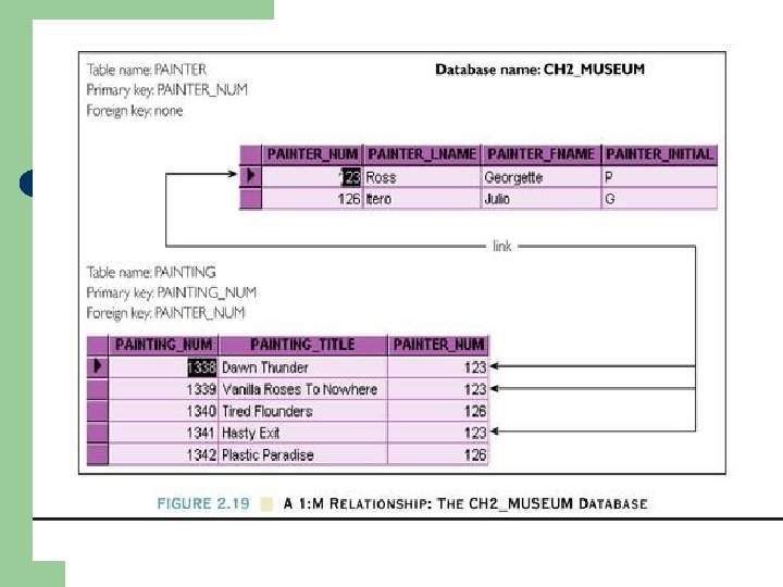
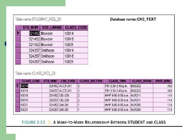
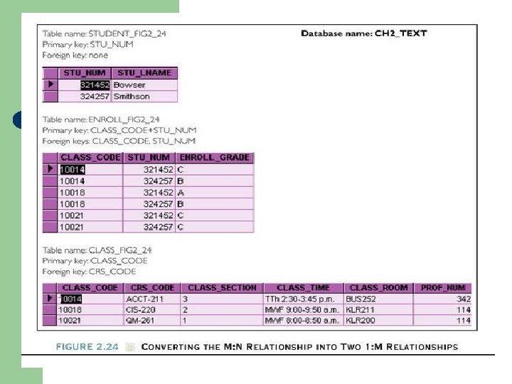
Relationships within the relational database: • • One-to-one relationships: One-to many relationships: • Examples: • • • professor - class department - employee Many to-many relationships • • Examples: parts – product, student – class, … it is recommended to break it into a set (usually two) of one-to-may relationships through a so called composite (bridge) entity

Enterprise data planning • A large component of the business informational needs can be captured by the mapping of all entities the organizations need to keep track of and the relationships among them • E-R (Entity-Relationship) modeling is a standard technique that provides a simplified picture of the relationship among entities.
 is")
Entities and Attributes l Entities and Attributes – An entity (or entity instance) is a person, place, event, or thing for which we intend to collect data. l l – University -- Students, Faculty Members, Courses Airlines -- Pilots, Aircraft, Routes, Suppliers Each entity has certain characteristics known as attributes. l l Student -- Student Number, Name, GPA, Date of Enrollment, Date of Birth, Home Address, Phone Number, Major Aircraft -- Aircraft Number, Date of Last Maintenance, Total Hours Flown, Hours Flown since Last Maintenance
 elements: – Rectangles are used to represent entities.")
E-R Diagrams l E-R Diagram (ERD) elements: – Rectangles are used to represent entities. – Diamonds are used to represent the relationship(s) between the entities. – The number 1 is used to represent the “ 1” side of the relationship. – The letter M is used to represent the “many” sides of the relationship.

1 to Many Relationship

1 to Many Relationship: another example

Many to Many Relationship

E-R Diagram: An example
b7be9dbc34b729e1dde0f5447ceef49d.ppt