

0cca7932112885b1a49fb5ce8a43d18e.ppt
- Количество слайдов: 77
 Introduction
 What are Non-Functional Requirements ? • NFRs are also known as Quality Requirements [Chung 93] [Boehm 96]. • Unlike Functional Requirements, Non-Functional requirements states constraints to the system as well as particular behavior that the system must have. • Non-Functional Requirements are always together with a Functional Requirement [EAGLE 95][Chung 00].
 Non-Functional Requirements examples • • • • Adaptability Architectural integrity Cost Configurability Efficiency Maintainability Flexibility Profitability Performance Usability Understandability Risk Resilience Reusability • • • • Time to Market Reliability Security Modularity Portability Size Safety Testability Mobility Standard compliant Robustness NFRs are important for the success of Complexity the system !! Learnability
 Why bother with Non-Functional Requirements
 -- Microsoft's chairman, Bill") A Recent Press Release WASHINGTON (AP, Jan 17 th 2002) -- Microsoft's chairman, Bill Gates, is steering his software empire onto a new strategic heading, putting security and privacy ahead of new capabilities [new functionality] in the company's products. In an e-mail to employees obtained by The Associated Press, Gates refers to the new philosophy as "Trustworthy Computing" and says highest priority is to ensure that computer users continued to venture safely across an increasingly Internet-connected world.
A Recent Press Release WASHINGTON (AP, Jan 17 th 2002) -- Microsoft's chairman, Bill Gates, is steering his software empire onto a new strategic heading, putting security and privacy ahead of new capabilities [new functionality] in the company's products. In an e-mail to employees obtained by The Associated Press, Gates refers to the new philosophy as "Trustworthy Computing" and says highest priority is to ensure that computer users continued to venture safely across an increasingly Internet-connected world.
 The London Ambulance System was deactivated just after") Another case neglecting non-functional requirements (NFRs) The London Ambulance System was deactivated just after its deployment because, among other reasons, many nonfunctional requirements were neglected during the system development e. g. reliability (vehicles location), cost (emphasis on the best price), usability (poor control of information on the screen), performance (the system did what was supposed to do but he performance was unacceptable), [Finkelstein 96] [Breitman et all 99].
Another case neglecting non-functional requirements (NFRs) The London Ambulance System was deactivated just after its deployment because, among other reasons, many nonfunctional requirements were neglected during the system development e. g. reliability (vehicles location), cost (emphasis on the best price), usability (poor control of information on the screen), performance (the system did what was supposed to do but he performance was unacceptable), [Finkelstein 96] [Breitman et all 99].
 Why Non-Functional Requirements ? § Nowadays, the market demands more and more non-functional aspects to be implemented in information systems besides its functionality. § Works [Dardene 93] [Mylopoulos 92] [Chung 95] have shown that complex conceptual models must deal with non-functional aspects. § This Non-Functional aspects should be dealt within the process of Non-Functional Requirements (NFR) definition.
 Why Non-Functional Requirements ? § Errors due to omission of NFRs or to not properly dealing with them are among the most expensive type and most difficult to correct [Mylopoulos 92] [Ebert 97] [Cysneiros 99]. § Recent works point out that early-phase Requirements Engineering should address organizational and Non. Functional Requirements, while later-phase focus on completeness, consistency and automated verification of requirements [Yu 97].
 Why Non-Functional Requirements ? § Few works addresses the integration of early and late requirements [Yu u 95] [Cysneiros 99]. § Interdependencies between NFRs must be identified and dealt with. For Example : § § § A Clinical Analysis Lab information system has the following Functional Requirement. • The system must have a file containing all the clients to be used by the Marketing Division. Together with this Functional Requirements we have the following NFR: • This file must be complete enough to allow the Marketing Division to prospect new clients. But an NFR associated with the Client’s attendance states: • Patient’s admission must last less then 4 minutes.
 Functional x Non-Functional Requirement • Suppose we are dealing with a Clinical Analysis Laboratory software system. • There will be a Functional Requirement: • “The System must provide a data entry to input the results of tests to a patient’s report” • Associated to this Requirement one may find the following Security NFR: • “Depending on the result of a test only the supervisor will be able to input this value to the patient’s report”
 Functional x Non-Functional Requirement • NFRs define global constraints – on a software system or subsystem, – a functional requirement, – the development or – deployment processes • FRs are local in nature (often defined as scenarios of interactions with the system) • NFRs are often subjective in nature • FRs are objective in nature. • NFRs are generally stated – informally, – are often contradictory, – difficult to enforce during development – Difficult to evaluate for the customer prior to delivery. • FRs are generally stated – more formally (structured english, Use Cases/UML, formal methods) – Usually do not conflict with each other. – Achieving FRs can be enforced by todays design methods – FRs can be evaluated by customers.
 Approaches For Dealing with NFRs u Product-Oriented • The focus is on the final product. • Almost always uses a quantitative approach. • Only measure what did or did not do. Do not help to prevent problems. • Most of the NFR work use this approach [Keller 90] [Boehm 78] [Basili 91] [Hauser 88].
 Lets") Quantitative approach Maintainability comparison Measured value Software Object Measurement system Desired value (3) Lets compare the measured value with a desired value (2) Lets measure the degree to which it meets maintainability using some maintainability metric. (1) Given an existing software object
Quantitative approach Maintainability comparison Measured value Software Object Measurement system Desired value (3) Lets compare the measured value with a desired value (2) Lets measure the degree to which it meets maintainability using some maintainability metric. (1) Given an existing software object
 Approaches to Deal with NFRs u Process-Oriented • The focus is on the software development process. • Aims to help finding out the necessary NFRs during the development process. • Always use a qualitative approach. • Aims to help justifying design decisions. • Few works use this approach [Dobson 91] [Chung 00] [Cysneiros 99].
 Given two existing software objects good Software") Qualitative approach Maintainability Not so good (1) Given two existing software objects good Software Object 1 (2) Lets compare them with each other and see which one achieves maintainability, relatively speaking, better Software Object 2 Bad good Some ordering vis-à-vis maintainability
Qualitative approach Maintainability Not so good (1) Given two existing software objects good Software Object 1 (2) Lets compare them with each other and see which one achieves maintainability, relatively speaking, better Software Object 2 Bad good Some ordering vis-à-vis maintainability
 Measuring software object Product vs. Process Maintainability comparison Measurement system Desired value Maintainability") (2) Measuring software object Product vs. Process Maintainability comparison Measurement system Desired value Maintainability Performance (1) How can maintainability be achieved ? (3) May hurt performance of the system Measured value (1) Existing software object Software object (2) By using encapsulation techniques to establish Interfaces interfaces. Software Objects Product approach Process approach
(2) Measuring software object Product vs. Process Maintainability comparison Measurement system Desired value Maintainability Performance (1) How can maintainability be achieved ? (3) May hurt performance of the system Measured value (1) Existing software object Software object (2) By using encapsulation techniques to establish Interfaces interfaces. Software Objects Product approach Process approach
 Approaches to Deal with NFRs § Product and Process-oriented complementary to each other. approaches are § Product-oriented approaches can provide you with tools to validate the product. § Process-oriented approaches can guide in searching for ways to achieve NFRs while developing the software.
 Eliciting is not Enough • Integrating NFRs into data models can help to get software deployed faster and with lower development costs [Cysneiros 99].
 Our Proposal • We propose a strategy to deal with NFR since the early stages of software development • The first part presents some heuristics to elicit NFR and a systematic way to search for interdependencies Ø Uses the Language Extended Lexicon (LEL) [Leite 93] as an anchor for the definition of the non-functional model • The second part presents some heuristics to integrate NFRs into conceptual models Ø Also uses the LEL as an anchor to build the functional model Ø Extends the scenario model [Leite 97], the class, sequence and collaboration diagrams [Rumbaugh 99] to deal with NFR
 The Proposed Strategy
 Sequence Diagram Functional View Class Diagram Use Cases Collaboration Diagram Scenarios New Actors and Use Cases LEL New Episodes, Resources and Actors New Classes, Operations and Attributes New Classes, and messages NFR and its impacts NFR Graph Non-Functional View
 Building the Non-Functional View Client Changes due to Conflict Resolution Knowledge on the Problem Introduce NFRs in the LEL New Notions New Behavioral Responses New Symbols Positive and Negative Influences Conflicts Design Decisions NFR Graph LEL with NFRs 1 LEL Symbol LEL 2 Primary NFR Knowledge Base on NFRs Identify and Solve Conflicts Represent NFR Interdependencies 3
 NFR Taxonomy • A NFR can be classified as Primary and Secondary ones where the secondary once is a decomposition of a Primary one • For Examples: Ø Accuracy v Numeric v Write information at the right time Primary Secondary • Dynamic NFR Ø Are those that deal with more abstract concepts and frequently demands an action to be • Static NRR Ø This type of NFR always demands some information to be used, usually in a persistent way
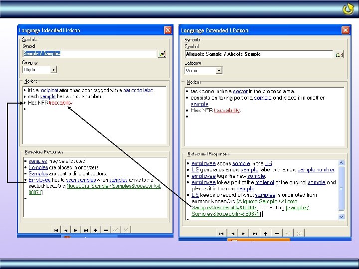
 • Aims to register the vocabulary used in the Uof.") Language Extended Lexicon (LEL) • Aims to register the vocabulary used in the Uof. D • It is based on a system of symbols composed of Notions and Behavioural Responses • Notions specify the meaning of the symbol (denotation) • Behavioural Responses register the results driven from the symbol utilization (connotation) • Its construction is based on the minimum vocabulary and circularity principles
Language Extended Lexicon (LEL) • Aims to register the vocabulary used in the Uof. D • It is based on a system of symbols composed of Notions and Behavioural Responses • Notions specify the meaning of the symbol (denotation) • Behavioural Responses register the results driven from the symbol utilization (connotation) • Its construction is based on the minimum vocabulary and circularity principles
 LEL – Proposed Extension • We now register Primary NFR in the notion of the symbols • We register the fact that a notion or a behavioural response is stated for satisfying an NFR from another symbol (eventually from the same symbol) • We can now show what notions and behavioural responses are necessary to satisfy an NFR
 Building the Non-Functional View Client Changes due to Conflict Resolution Knowledge on the Problem Add NFRs to the LEL New Notions New Behavioral Responses New Symbols Positive and Negative Influences Conflicts Design Decisions NFR Graph LEL with NFRs 1 LEL Symbol LEL 2 Primary NFR Knowledge Base on NFRs Identify and Solve Conflicts Represent NFR Interdependencies 3
 Add NFRs to the LEL • To each symbol of the LEL : – Check if any NFR belonging to the Knowledge Base may be necessary in this symbol – If it is true, represent it in the Notion – Evaluate the possible consequences in this symbol and in other symbols due to NFR satisfaction – Establish a dependency link between these notion and behavioural Reponses to this NFR
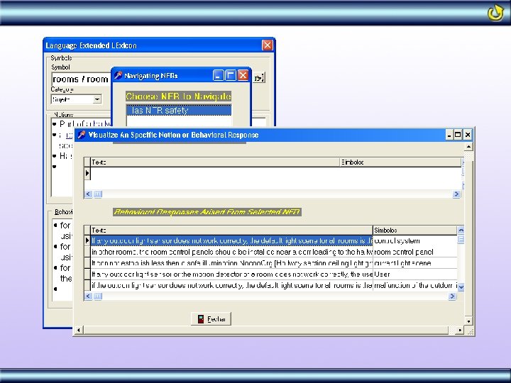
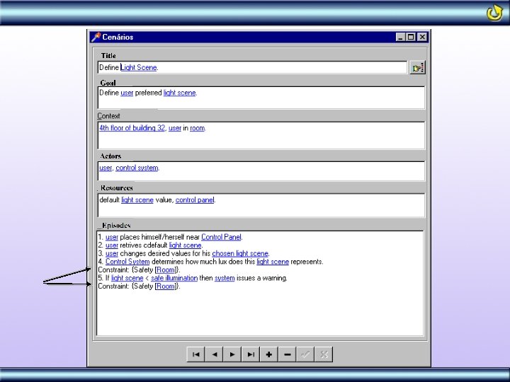
 Example What NFR is Needed ?
 Building the Non-Functional View Client Changes due to Conflict Resolution Knowledge on the Problem Add NFRs to the LEL New Notions New Behavioral Responses New Symbols Positive and Negative Influences Conflicts Design Decisions NFR Graph LEL with NFRs 1 LEL Symbol LEL 2 Primary NFR Knowledge Base on NFRs Identify and Solve Conflicts Represent NFR Interdependencies 3
 Represent NFR • We propose the use of the NFR Framework • NFR are represented using a graph structure very similar to the And/Or trees used in problem solving • NFR are faced as softgoals that might be decomposed into more refined subgoals until we get the subgoals that will represent how this NFR will be operationalized (its operationalizations) • One system can have (usually does) n graphs Satisfice • NFR are rarely 100% satisfied X Satisfy • Some proposed extensions Ø Always use a symbol of the LEL to represent an NFR Topic Ø Represent above the graph the actor(s) responsible for the knowledge represented in the graph Ø Introduces the concept of Dynamic and Static Operationalizations
![Actor who was the source of the Knowledge Facility Manager S Safety [Room] Topic](https://present5.com/presentation/0cca7932112885b1a49fb5ce8a43d18e/image-32.jpg "Actor who was the source of the Knowledge Facility Manager S Safety [Room] Topic") Actor who was the source of the Knowledge Facility Manager S Safety [Room] Topic has to be a symbol of the LEL Safety [Room. Light scene. Current light scene >= Safe Illumination] Safety [Malfunction of OLS ] Safety [Light Scene. Safe Illumination=14 Lux] Static Operationalization S Safety [Malfunction of OLS. All CLG set on] Safety [Room. Malfunction] S S Safety [Malfunction. Motion Detector] Safety [Malfunction. User. Get informed] S S Safety [Room. Control Panel] Safety [Malfunction. FM Get informed] S Safety [Located Near the Door] S = Satisficed P = Partially D = Denied Dynamic Operationalization
Actor who was the source of the Knowledge Facility Manager S Safety [Room] Topic has to be a symbol of the LEL Safety [Room. Light scene. Current light scene >= Safe Illumination] Safety [Malfunction of OLS ] Safety [Light Scene. Safe Illumination=14 Lux] Static Operationalization S Safety [Malfunction of OLS. All CLG set on] Safety [Room. Malfunction] S S Safety [Malfunction. Motion Detector] Safety [Malfunction. User. Get informed] S S Safety [Room. Control Panel] Safety [Malfunction. FM Get informed] S Safety [Located Near the Door] S = Satisficed P = Partially D = Denied Dynamic Operationalization
![How to Create a Graph Safety [Room]](https://present5.com/presentation/0cca7932112885b1a49fb5ce8a43d18e/image-33.jpg "How to Create a Graph Safety [Room]") How to Create a Graph Safety [Room]
How to Create a Graph Safety [Room]
![A First Decomposition Safety [Room] S S Safety [Room. Light Scene. Safe Illumination=14 lux]](https://present5.com/presentation/0cca7932112885b1a49fb5ce8a43d18e/image-35.jpg "A First Decomposition Safety [Room] S S Safety [Room. Light Scene. Safe Illumination=14 lux]") A First Decomposition Safety [Room] S S Safety [Room. Light Scene. Safe Illumination=14 lux] S Safety [Malfunction of OLS. All CLG set on] S Safety [Malfunction. User. Get informed] S Safety [Located Near the Door]
A First Decomposition Safety [Room] S S Safety [Room. Light Scene. Safe Illumination=14 lux] S Safety [Malfunction of OLS. All CLG set on] S Safety [Malfunction. User. Get informed] S Safety [Located Near the Door]
![Final Version Facility Manager S Safety [Room] Safety [Room. Light scene. Current light scene](https://present5.com/presentation/0cca7932112885b1a49fb5ce8a43d18e/image-36.jpg "Final Version Facility Manager S Safety [Room] Safety [Room. Light scene. Current light scene") Final Version Facility Manager S Safety [Room] Safety [Room. Light scene. Current light scene >= Safe Illumination] Safety [Malfunction of OLS ] Safety [Light Scene. Safe Illumination=14 Lux] S Safety [Malfunction of OLS. All CLG set on] Safety [Room. Malfunction] S S Safety [Malfunction. Motion Detector] Safety [Malfunction. User. Get informed] S S Safety [Room. Control Panel] Safety [Malfunction. FM Get informed] S Safety [Located Near the Door]
Final Version Facility Manager S Safety [Room] Safety [Room. Light scene. Current light scene >= Safe Illumination] Safety [Malfunction of OLS ] Safety [Light Scene. Safe Illumination=14 Lux] S Safety [Malfunction of OLS. All CLG set on] Safety [Room. Malfunction] S S Safety [Malfunction. Motion Detector] Safety [Malfunction. User. Get informed] S S Safety [Room. Control Panel] Safety [Malfunction. FM Get informed] S Safety [Located Near the Door]
 Building the Non-Functional View Client Changes due to Conflict Resolution Knowledge on the Problem Add NFRs to the LEL New Notions New Behavioral Responses New Symbols Positive and Negative Influences Conflicts Design Decisions NFR Graph LEL with NFRs 1 LEL Symbol LAL 2 Primary NFR Knowledge Base on NFRs Identify and Solve Conflicts Represent NFR Interdependencies 3
 2.") Identify and Solve Conflicts 1. Compare graphs with the same type (ex: Performance) 2. Using the Knowledge Base from the OORNF Tool, compare graphs with conflicting types (Ex: Security and Performance or Usability) 3. Pair wise graphs For each of the above heuristics: – Register positive and negative interdependencies – Try to solve possible conflicts (negative interdependencies)
Identify and Solve Conflicts 1. Compare graphs with the same type (ex: Performance) 2. Using the Knowledge Base from the OORNF Tool, compare graphs with conflicting types (Ex: Security and Performance or Usability) 3. Pair wise graphs For each of the above heuristics: – Register positive and negative interdependencies – Try to solve possible conflicts (negative interdependencies)
 Example Manager of the Processing Area Manager of the Medical Bureau P Claim [As soon as al the results are ready and reviewed the report must be printed] D P P P S Op. Restriction [ Patient’s Report] S - Time Restrictions [ Print Patient’s Report ] S P P Time Restrictions [ Admitted Tests] Time restrictions [LIS. Eletronicaly Signs Patient’s Report] S S Time restrictions [ Medical Bureau. Eletronicaly Signs Patient’s Report] . Time restrictions [ Medical Bureau. . Eletronical Signature ] Reliability [ Eletronicaly sign Patient’s Report] S Reliability [Range to be Eletronicaly signed ] Time Restrictions [ Results Ready] Time Restrictions [ Results to Inspect] Reliability [test] S Reliability [LIS. signs if all results are within range] Time restrictions [LIS. Printing queue for Patient’s Report]
 Using Catalogues – Another Alternative Softgoal Operationalization Claim Contribution Link Correlation Link
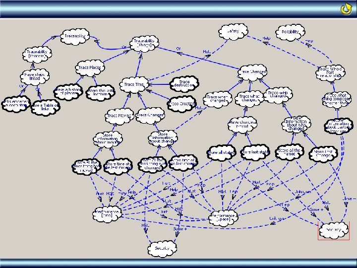
![S S Traceability [ Test Results] Traceability [ Changes] Traceability [ Who entered results]](https://present5.com/presentation/0cca7932112885b1a49fb5ce8a43d18e/image-42.jpg "S S Traceability [ Test Results] Traceability [ Changes] Traceability [ Who entered results]") S S Traceability [ Test Results] Traceability [ Changes] Traceability [ Who entered results] S Traceability [ Store Identification of ALL Who entered results] Traceability [ When results Changed] S S Traceability [What Results] Traceability [ Store Date and time of ALL result changes] S Traceability [ Store ALL results]
S S Traceability [ Test Results] Traceability [ Changes] Traceability [ Who entered results] S Traceability [ Store Identification of ALL Who entered results] Traceability [ When results Changed] S S Traceability [What Results] Traceability [ Store Date and time of ALL result changes] S Traceability [ Store ALL results]
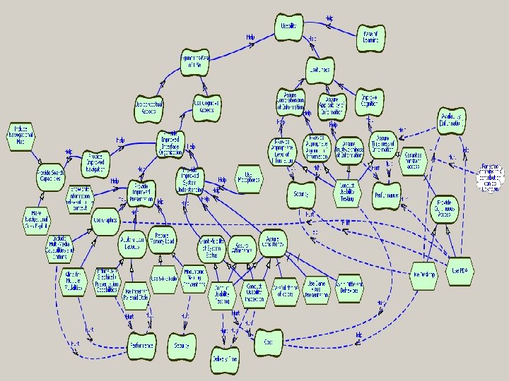
![Usability [ Patient Adviser] S S Usaability [ Improve Cognition] S Usability [ Assure](https://present5.com/presentation/0cca7932112885b1a49fb5ce8a43d18e/image-44.jpg "Usability [ Patient Adviser] S S Usaability [ Improve Cognition] S Usability [ Assure") Usability [ Patient Adviser] S S Usaability [ Improve Cognition] S Usability [ Assure Timeliness of Information] S Usability [ Provide Improved Presentation] P Usability [Reduce Memory Load] Usability [ Provide Coninuoes Access] S Usability [Use a PDA] S S + + - D Security [ Patient’s Record] Usability [Use 5+2 Rule] Usability [Use Graphics] D Usability [Use a Desktop] D + D D Cost [ Patient Adviser] + S Availability [ Patient’s Record] Usability [Allow for Multiple Modality]
Usability [ Patient Adviser] S S Usaability [ Improve Cognition] S Usability [ Assure Timeliness of Information] S Usability [ Provide Improved Presentation] P Usability [Reduce Memory Load] Usability [ Provide Coninuoes Access] S Usability [Use a PDA] S S + + - D Security [ Patient’s Record] Usability [Use 5+2 Rule] Usability [Use Graphics] D Usability [Use a Desktop] D + D D Cost [ Patient Adviser] + S Availability [ Patient’s Record] Usability [Allow for Multiple Modality]
 Extending Functional View Models
 Extending Use Cases • Every use case or actor included, due to NFR satisfaction, must be followed by an expression using the pattern: {NFR_Type[NFR_topic]}. • Represent Special Conditions that must prevail to an Use Case as a note linked to this Use Case, using whenever possible OCL to describe these conditions – Ex: In a Light Control System – The Use Case Turn Off Lights after T 3 Sec must have a special condition saying that this will only happen if the room is empty – We should them represent it as: Pre: room. number_people=0
![Example Verify Access {Security[Input Results]} Processing Area Employee Pick Up a Patient LIS {pre:](https://present5.com/presentation/0cca7932112885b1a49fb5ce8a43d18e/image-47.jpg "Example Verify Access {Security[Input Results]} Processing Area Employee Pick Up a Patient LIS {pre:") Example Verify Access {Security[Input Results]} Processing Area Employee Pick Up a Patient LIS {pre: (employee. sector=test. sector AND test. result in est. saferange) OR employee. position=“SM”} {Security[Input Results]} Set Result Check Sector {Security[Input Results]} Check If results are in Range {Security[Input Results]}
Example Verify Access {Security[Input Results]} Processing Area Employee Pick Up a Patient LIS {pre: (employee. sector=test. sector AND test. result in est. saferange) OR employee. position=“SM”} {Security[Input Results]} Set Result Check Sector {Security[Input Results]} Check If results are in Range {Security[Input Results]}
![Extending Scenarios [Leite 97] • Every change in a scenario due to an NFR](https://present5.com/presentation/0cca7932112885b1a49fb5ce8a43d18e/image-48.jpg "Extending Scenarios [Leite 97] • Every change in a scenario due to an NFR") Extending Scenarios [Leite 97] • Every change in a scenario due to an NFR satisficing must be followed by the expression : Constraint: {NFR[Topic]} • Reason: Traceability between models
Extending Scenarios [Leite 97] • Every change in a scenario due to an NFR satisficing must be followed by the expression : Constraint: {NFR[Topic]} • Reason: Traceability between models
 Extending the Class Diagram • Every class will be named using a symbol of the LEL • Classes created due to an NFR satisficing will be follwed by the same traceability pattern used in scenarios. Status. Line {Usability [Room Control Panel]} Place : Integer CLG 1 : Boolean CLG 2 : Boolean Set. CLGOn (Number) {Usability [Room Control Panel]} Set. CLGOff (Number) {Usability [Room Control Panel]}
 • Operations that are in the class due") Extending the Class Diagram (cont. ) • Operations that are in the class due to an NFR satisficing will always be followed by the same kind of expression used in scenarios : {NFR[Topic]} • We may have to represent special conditions that holds for an operation. These conditions will be represented between {} and must use, whenever possible, expressions written using OCL • If these conditions impose a significant loss of space, we might represent them inside a note
Extending the Class Diagram (cont. ) • Operations that are in the class due to an NFR satisficing will always be followed by the same kind of expression used in scenarios : {NFR[Topic]} • We may have to represent special conditions that holds for an operation. These conditions will be represented between {} and must use, whenever possible, expressions written using OCL • If these conditions impose a significant loss of space, we might represent them inside a note
![Example Place Advise. Userof. Malfunction() {Safety [Room]} Advise. FMof. Malfunction {Safety [HS] Get. OLSValue()](https://present5.com/presentation/0cca7932112885b1a49fb5ce8a43d18e/image-52.jpg "Example Place Advise. Userof. Malfunction() {Safety [Room]} Advise. FMof. Malfunction {Safety [HS] Get. OLSValue()") Example Place Advise. Userof. Malfunction() {Safety [Room]} Advise. FMof. Malfunction {Safety [HS] Get. OLSValue() {Op. Cost [Control System]} Set. Room. As. Occupied() {Accuracy [Room]} Increment_people() {Accuracy [Room]} Decrement_people() {Accuracy [Room]} Turn. On. Emergency() : void Quit() : void Turn. Off() : void Set. Room. As. Occupied() pre: malfunction of Msensor Increment_people() Pre: Motion sensor sends signal Post: NR_i_people=NR_i_people@pre+1 Decrement_people() Pre: Motion sensor sends signal post: NR_i_people=NR_i_people@pre-1
Example Place Advise. Userof. Malfunction() {Safety [Room]} Advise. FMof. Malfunction {Safety [HS] Get. OLSValue() {Op. Cost [Control System]} Set. Room. As. Occupied() {Accuracy [Room]} Increment_people() {Accuracy [Room]} Decrement_people() {Accuracy [Room]} Turn. On. Emergency() : void Quit() : void Turn. Off() : void Set. Room. As. Occupied() pre: malfunction of Msensor Increment_people() Pre: Motion sensor sends signal Post: NR_i_people=NR_i_people@pre+1 Decrement_people() Pre: Motion sensor sends signal post: NR_i_people=NR_i_people@pre-1
 • Attributes included in class to satisfice an") Extending the Class Diagram (cont. ) • Attributes included in class to satisfice an NFR will be preceded of NR_ in its names • If the Req. Eng. finds it is necessary, the attribute may be followed by the same kind of expression used before to add traceability: {NFR[topic]} Place timeto. Turn. Off: int default. Light. Level: int descriptio : String defauttimetto. Turn. Off: int NR_ i_People: int {Accuracy [Place]} NR_OLSValue : int NR_Turn. Off: Boolean
Extending the Class Diagram (cont. ) • Attributes included in class to satisfice an NFR will be preceded of NR_ in its names • If the Req. Eng. finds it is necessary, the attribute may be followed by the same kind of expression used before to add traceability: {NFR[topic]} Place timeto. Turn. Off: int default. Light. Level: int descriptio : String defauttimetto. Turn. Off: int NR_ i_People: int {Accuracy [Place]} NR_OLSValue : int NR_Turn. Off: Boolean
 The Integration Method
 Integrating NFR into Use Cases 6 Pick up next graph that applies New decisions on NFRs satisficing NFRs Graph Dynamic Operationalizations NFR graph where The symbols appears 4 Analyze possible impacts due to inclusions made in the Use Case Diagram 3 Evaluate again Evaluate necessary inclusions s to satisfice this NFR in the Use Case Diagram 2 Identify LEL symbols that appears in Use Cases Names and Actors 5 New Use Cases or actors Special Conditions New scenario 1 Pick up a Use Case Diagran Use Cases Names Acotrs Use Case Map Do it until there is no Use Case Diagram left to analyze 7
 Example of Integration into Use Cases Manager of the Processing Area Manager of Quality Assurance S Traceability [Sample] Sorting Area Employee Get Samples S Traceability [Moviment ] S Split Samples According to Sector S Traceability [Alicoting ] Traceability [Scan sample everytime it moves from place to place Take Samples to Sector S Processing Area Employee Place Samples in Trays Traceability [Place where it was ] S Traceability [Place where it went to ] S Traceability [Who scanned]
 Get Samples Sorting Area Employee Split") Example of Integration into Use Cases (Cont. ) Get Samples Sorting Area Employee Split Samples According to Sector Scan Samples {Traceability[Sample]} Take Samples to Sector Processing Area Employee Place Samples in Trays
Example of Integration into Use Cases (Cont. ) Get Samples Sorting Area Employee Split Samples According to Sector Scan Samples {Traceability[Sample]} Take Samples to Sector Processing Area Employee Place Samples in Trays
 Integrating NFR into Scenarios 6 Pick up next graph that applies New decisions on NFRs satisficing NFRs Graph Dynamic Operationalizations NFR graph where The symbol appears 4 Analyze possible impacts due to inclusions made in the scenario 3 Evaluate again Evaluate necessary inclusions s to satisfice this NFR in the scenario 2 1 Analyze cenários with titles that has LAL symbols which appears in an NFR graph 5 New episodes, actors and resources Scenario New scenario Scenarios Pick up a scenario Scenario title Do it until there is no scenario left to analyze 7
![Example of Scenarios Integration S S Safety [ Dim Lights] Safety [ Dim Lights.](https://present5.com/presentation/0cca7932112885b1a49fb5ce8a43d18e/image-59.jpg "Example of Scenarios Integration S S Safety [ Dim Lights] Safety [ Dim Lights.") Example of Scenarios Integration S S Safety [ Dim Lights] Safety [ Dim Lights. Room. Illumination >=14 lux] Safety [Room. Calculate Lux. Value] Safety [Room. Lux. Value] ]
Example of Scenarios Integration S S Safety [ Dim Lights] Safety [ Dim Lights. Room. Illumination >=14 lux] Safety [Room. Calculate Lux. Value] Safety [Room. Lux. Value] ]
") Example of Scenarios Integration (Cont. )
Example of Scenarios Integration (Cont. )
 Integrating NFR into Class Diagram 6 Pick up next graph that applies New decisions on NFRs satisficing NFR Graphs Static Operationalizations Dynamic Operationalizations NFR Graph where the name of the chosen class appears 4 Analyze possible impacts due to inclusions made in the class diagram 3 5 Evaluate necessary inclusions s to satisfice this NFR in the class diagram Look for NFRs that applies to this class New classes, attributes e and operations 2 Class, Attributes and Operations Pick up a Class 1 Evaluate again New Design Class Diagram Do it until there is no classes left to analyze 7
 Sequence and Collaboration Diagrams Special Conditions New Messages / New Classes Sequence Diagram Verify if operation requires any messages or special conditions to be included New Messages / New Classes 2 Special conditions Pick up a classe with NFR 1 Class Diagram Operations due to NFRs satisficing Colaboration Diagram
 Examples From a Case Study
![Strategy Validation • • • Strongly based on the replication project principle [Basili 96]](https://present5.com/presentation/0cca7932112885b1a49fb5ce8a43d18e/image-64.jpg "Strategy Validation • • • Strongly based on the replication project principle [Basili 96]") Strategy Validation • • • Strongly based on the replication project principle [Basili 96] 3 different case studies 2 in vitro (Controlled Environment) 1 in vivo (Real Application Environment) In all the 3 cases we used conceptual models built by the other teams and we applied the proposed strategy – We built the Non-Functional View – We integrated the NFRs from this view into the conceptual models developed by the other teams
Strategy Validation • • • Strongly based on the replication project principle [Basili 96] 3 different case studies 2 in vitro (Controlled Environment) 1 in vivo (Real Application Environment) In all the 3 cases we used conceptual models built by the other teams and we applied the proposed strategy – We built the Non-Functional View – We integrated the NFRs from this view into the conceptual models developed by the other teams
 Case Studies • Case Study I Ø Light Control System following a proposal presented in a Dagstuhl Seminar. Conducted by Breitman [Breitman 00] as one of the case studies of her Ph. D. thesis. • Case Study II Ø Another specification of Light Control System, built by a group of undergraduate students from the Computer Science Course of PUC_Rio • Case Study III Ø A Laboratory Information System (LIS) developed by a team from a software house specialized in this domain. We used the conceptual model restricted to the processing area
 Details on Case Study III • We built the LEL with the NFR using structured interviews and existing documentation • From this LEL we built the set of NFR graphs • We validated this graphs together with the stakeholders • After this validation we did the integration between the functional and the non-functional views • Several changes were made in the existing class diagram
 Integrating NFR into Use Cases Manager of Biochemestry Manager of Hematology Input Results Use Case Diagram Security [Input Results] S S Verify Access Security [Regular Check] LIS Security [Check if is employee is from the same sector where the test is processed] S Security [Check if result is within permited value ] S Pick Up a Patient Processing Area Employee S Security [aditional Check] S Securityif [Check employee is authorized ] Set Results S Security [Acess information] S Security [Employee. Position=“SM”] S S Security [Test. Safe Range] S Security S [Maximum] [Minimum] Security [Test. Sector] S Security [Employee. Sector]
![Resulting Use Case Diagram Verify Access {Security[Input Results]} Processing Area Employee Pick Up a](https://present5.com/presentation/0cca7932112885b1a49fb5ce8a43d18e/image-68.jpg "Resulting Use Case Diagram Verify Access {Security[Input Results]} Processing Area Employee Pick Up a") Resulting Use Case Diagram Verify Access {Security[Input Results]} Processing Area Employee Pick Up a Patient LIS {pre: (employee. sector=test. sector AND test. result in est. saferange) OR employee. position=“SM”} {Security[Input Results]} Set Result Check Sector {Security[Input Results]} Check If results are in Range {Security[Input Results]}
Resulting Use Case Diagram Verify Access {Security[Input Results]} Processing Area Employee Pick Up a Patient LIS {pre: (employee. sector=test. sector AND test. result in est. saferange) OR employee. position=“SM”} {Security[Input Results]} Set Result Check Sector {Security[Input Results]} Check If results are in Range {Security[Input Results]}
 Using Another LEL Symbol Manager of the Processing area S D Claim[“Only results within certain limits can be assigned to patient’s report without review] S S Value [Automatic Assignment] Value [LIS. Check if Value is within range] S Reliability [Test Result] S S S Value [Test Result] Value [Normal Range] Value [LIS. Tag results out of Normal Range] S S Value [Repeat Test] Accuracy [LIS. Mark Test to be repeated] S Accuracy [LIS. Send Test to be repeated to Analyzer] Correctness [Test Result]
![Part of the Resulting Use Case Diagram Verify Access {Security[Input Results]} Pick Up a](https://present5.com/presentation/0cca7932112885b1a49fb5ce8a43d18e/image-70.jpg "Part of the Resulting Use Case Diagram Verify Access {Security[Input Results]} Pick Up a") Part of the Resulting Use Case Diagram Verify Access {Security[Input Results]} Pick Up a Patient Processing Area Employee LIS Set Result {pre: (employee. sector=test. sector AND test. result in est. saferange) OR employee. position=“SM”} {Security[Input Results]} Check Sector {Security[Input Results]} Tag Results Out of Range {Reliability [Test Result]} Check If results are in Range {Security[Input Results]} Mark Test To be Repeatedt {Reliability [Test Result] }
Part of the Resulting Use Case Diagram Verify Access {Security[Input Results]} Pick Up a Patient Processing Area Employee LIS Set Result {pre: (employee. sector=test. sector AND test. result in est. saferange) OR employee. position=“SM”} {Security[Input Results]} Check Sector {Security[Input Results]} Tag Results Out of Range {Reliability [Test Result]} Check If results are in Range {Security[Input Results]} Mark Test To be Repeatedt {Reliability [Test Result] }
 Using the Strategy on the Class “Result to Inspect” Manager of Biochemestry S S Traceability [Result to Inspect] Traceability [LIS. Keeps historical Log of who has assigned which results ] S Traceability [ Log of Inspection ] Log of Inspection {Traceability [Inspect Tests]} S Traceability [Who used] S Traceability [When used] Traceability S [Which Result] Sample. Number Date Time Test Result Employee Create. Log() Add. Registerto. Log() Searchby. Sample() Searchby. Patient() Searchby. Date()
 Using the Strategy on the Class “Medical Bureau” Medical Bureau NR_Elet. Signature {Op. Restriction [Patient’s Report] } Review. Patient. Report() Print. Delayed. Report() Print. Promissed. Report() Get. Signature {Op. Restriction [Patient’s Report]} Set. Signature {Op. Restriction [Patient’s Report]}
 Applying the Strategy on Sequence Diagrams Review Patient Report : Medical Bureau : Visit : Admitted Tests : Patient's Report * Get. Sample. Number( ) Get. Admitted. Tests( ) Get. Result( ) [ Se Nao OK] Set. Patientto. Review( ) [Se OK] Print. Patient. Report( ) : Sector
 Review Patient Report : Medical Bureau : Visit : Admitted Tests : Patient's Report * Get. Sample. Number( ) Get. Admitted. Tests( ) Get. Result( ) [ Se Nao OK] Set. Patientto. Review( ) Get. Signature( ) {Op. Restriction [Patient's report]} [Se OK] Print. Patient. Report(NR_Elet. Signature) : Sector
 Consolidating the Case Studies • • 46% of the Existing Classes were somehow changed 45% more operation 37% more attributes Estimated Overhead of 7% Ø Case Study III v 1728 hours/man to build the functional view v 121 hours/man to build the non-functional view and to integrate it to the functional view v Compatible with the overhead of 10% found in a previous case study [Cysneiros 01]
![References § § § § J. § [Basili 91] Basili, V. and Musa, J.](https://present5.com/presentation/0cca7932112885b1a49fb5ce8a43d18e/image-76.jpg "References § § § § J. § [Basili 91] Basili, V. and Musa, J.") References § § § § J. § [Basili 91] Basili, V. and Musa, J. “The Future Engineering of Software a Management Perspective”, IEEE Computer 24 1991 pp: 90 -96 [Boehm 76] Boehm, B. , Brown, J. R. and Lipow, M. “Quantitative EVALUATION OF Software Quality” in Proc. of 2 nd International Conference on Soft. Eng. San Francisco, oct 1976, pp: 592 -605. [Boehm 78] Boehm, B. Characteristics of Software Quality. North Holland Press, 1978 [Boehm 96] Boehm, Barry e In, Hoh. Identifying Quality-Requirement Conflicts. IEEE Software, March 1996, pp. 2535 [Breitman et al 99] Breitman, K. K. , Leite J. C. S. P. e Finkelstein Anthony. The World's Stage: A Survey on Requirements Engineering Using a Real-Life Case Study. Journal of the Brazilian Computer Society No 1 Vol. 6 Jul. 1999 pp: 13: 37. [Breitman 00] Breitman, K. K. "Evolução de Cenários" Ph. D. Theses at PUC-Rio May 2000. [Chung 93]Chung L. , “Representing and Using Non-Functional Requirements: A Process Oriented Approach” Ph. D. Thesis, Dept. of Comp. Sci. University of Toronto, June 1993. Also tech. Rep. DKBS-TR-91 -1. [Chung 95] Chung, L. , Nixon, B. “Dealing with Non-Functional Requirements: Three Experimental Studies of a Process-Oriented Approach” Proc. 17 th Int. Con. on Software Eng. Seatle, Washington, April pp: 24 -28, 1995. [Chung 00] Chung, L. , Nixon, B. , Yu, Eric and Mylopoulos, M. “Non-Functional Requirements in Software Engineering” Kluwer Academic Publishers 1999. [Cysneiros 99] Cysneiros, L. M. and Leite, J. C. S. P. ‘Integrating Non-Functional Requirements into data model” 4 th International Symposium on Requirements Engineering – Ireland June 1999. [Cysneiros 01] Cysneiros, L. M. , Leite, J. C. S. P. and Neto, J. S. M. “A Framework for Integrating Non-Functional Requirements into Conceptual Models” Requirements Engineering Journal – Vol 6 , Issue 2 Apr. 2001, pp: 97 -115. [Dardenne 93] Dardenne, A. . van Lamsweerde A, Fickas, S. . “Goal Directed Requirements Acquisition”. Science of Computer Programming, Vol. 20 pp: 3 -50, Apr. 1993. [Dobson 91] Dobson, J. E. “On Non-Functional Requirements” PDCS Techinical Report Series University of Lancaster No 65 May 1991. [EAGLE 95] Evaluation of Natural Language Processing Systems, http: //www. issco. unige. ch/ewg 95 1995. [Ebert 97]Ebert, Christof. Dealing with Nonfunctional in Large Software Systems. Annals of Software Engineering, 3, 1997, pp. 367 -395. Dowelland [Finkelstein, A. 96] Study” Proceedings of the Eighth International Workshop on Software Specification and Design, IEEE Computer Society Press pp 2 -5 1996
References § § § § J. § [Basili 91] Basili, V. and Musa, J. “The Future Engineering of Software a Management Perspective”, IEEE Computer 24 1991 pp: 90 -96 [Boehm 76] Boehm, B. , Brown, J. R. and Lipow, M. “Quantitative EVALUATION OF Software Quality” in Proc. of 2 nd International Conference on Soft. Eng. San Francisco, oct 1976, pp: 592 -605. [Boehm 78] Boehm, B. Characteristics of Software Quality. North Holland Press, 1978 [Boehm 96] Boehm, Barry e In, Hoh. Identifying Quality-Requirement Conflicts. IEEE Software, March 1996, pp. 2535 [Breitman et al 99] Breitman, K. K. , Leite J. C. S. P. e Finkelstein Anthony. The World's Stage: A Survey on Requirements Engineering Using a Real-Life Case Study. Journal of the Brazilian Computer Society No 1 Vol. 6 Jul. 1999 pp: 13: 37. [Breitman 00] Breitman, K. K. "Evolução de Cenários" Ph. D. Theses at PUC-Rio May 2000. [Chung 93]Chung L. , “Representing and Using Non-Functional Requirements: A Process Oriented Approach” Ph. D. Thesis, Dept. of Comp. Sci. University of Toronto, June 1993. Also tech. Rep. DKBS-TR-91 -1. [Chung 95] Chung, L. , Nixon, B. “Dealing with Non-Functional Requirements: Three Experimental Studies of a Process-Oriented Approach” Proc. 17 th Int. Con. on Software Eng. Seatle, Washington, April pp: 24 -28, 1995. [Chung 00] Chung, L. , Nixon, B. , Yu, Eric and Mylopoulos, M. “Non-Functional Requirements in Software Engineering” Kluwer Academic Publishers 1999. [Cysneiros 99] Cysneiros, L. M. and Leite, J. C. S. P. ‘Integrating Non-Functional Requirements into data model” 4 th International Symposium on Requirements Engineering – Ireland June 1999. [Cysneiros 01] Cysneiros, L. M. , Leite, J. C. S. P. and Neto, J. S. M. “A Framework for Integrating Non-Functional Requirements into Conceptual Models” Requirements Engineering Journal – Vol 6 , Issue 2 Apr. 2001, pp: 97 -115. [Dardenne 93] Dardenne, A. . van Lamsweerde A, Fickas, S. . “Goal Directed Requirements Acquisition”. Science of Computer Programming, Vol. 20 pp: 3 -50, Apr. 1993. [Dobson 91] Dobson, J. E. “On Non-Functional Requirements” PDCS Techinical Report Series University of Lancaster No 65 May 1991. [EAGLE 95] Evaluation of Natural Language Processing Systems, http: //www. issco. unige. ch/ewg 95 1995. [Ebert 97]Ebert, Christof. Dealing with Nonfunctional in Large Software Systems. Annals of Software Engineering, 3, 1997, pp. 367 -395. Dowelland [Finkelstein, A. 96] Study” Proceedings of the Eighth International Workshop on Software Specification and Design, IEEE Computer Society Press pp 2 -5 1996
![§ Hauser 88] Hauser, J. R. and Hsiao, K. “The House of Quality”harvard Business](https://present5.com/presentation/0cca7932112885b1a49fb5ce8a43d18e/image-77.jpg "§ Hauser 88] Hauser, J. R. and Hsiao, K. “The House of Quality”harvard Business") § Hauser 88] Hauser, J. R. and Hsiao, K. “The House of Quality”harvard Business review, May 1998 pp: 63 -73 § [Keller 90] Keller, S. E. et al “Specifying Software Quality Requirements with Metrics” in Tutorial System and Software Requirements Engineering IEEE Computer Society Press 1990 pp: 145 -163 § [Kirner 96] Kirner T. G. , Davis A. M. , “Nonfunctional Requirements of Real-Time Systems”, Advances in Computers, Vol 42 pp 1 -37 1996. § [Leite 93] Leite J. C. S. P. and Franco, A. P. M. “A Strategy for Conceptual Model Acquisition ” in Proceedings of the First IEEE International Symposium on Requirements Engineering, San. Diego, Ca, IEEE Computer Society Press, pp 243246 1993. § [Leite 97] Leite, J. C. S. P. et. al. ” Enhancing a Requirements Baseline with Scenarios. ” Requirements Engineering Journal, 2(4): 184 -198, 1997. § § [Lindstrom 93] Lindstrom, D. R. Five Ways to Destroy a Development Project. IEEE Software, September 1993, pp. 55 -58. [Mylopoulos 92] Mylopoulos, J. Chung, L. , Yu, E. and Nixon, B. , “Representing and Using Non-functional Requirements: A Process-Oriented Approach. ” IEEE Trans. on Software Eng, 18(6), pp: 483 -497, June 1992. [Rumbaugh 99] Rumbaugh, J. , Jacobson, I. and Booch, G. "The Unified Modeling Language Reference Manual" , Addison -Wesley, 1999. [Sommerville 92] Sommerville, I. “Software Engineering” fourth edition, Addison-Wesley, 1992. [Yu 95] Yu, E. , Bois, P. and Mylopoulos, J. “From Organizational Models to System Requirements” The 3 rd International Conference on Cooperative Information Systems, Vienna, May 1995 [Yu 97] Yu, Eric “Towards Modelling and Reasoning Support for Early-Phase Requirements Engineering” Proc. of the 3 rd Interna. Symp. on Requirements Eng. Jan 1997 pp: 226 -235 § §
§ Hauser 88] Hauser, J. R. and Hsiao, K. “The House of Quality”harvard Business review, May 1998 pp: 63 -73 § [Keller 90] Keller, S. E. et al “Specifying Software Quality Requirements with Metrics” in Tutorial System and Software Requirements Engineering IEEE Computer Society Press 1990 pp: 145 -163 § [Kirner 96] Kirner T. G. , Davis A. M. , “Nonfunctional Requirements of Real-Time Systems”, Advances in Computers, Vol 42 pp 1 -37 1996. § [Leite 93] Leite J. C. S. P. and Franco, A. P. M. “A Strategy for Conceptual Model Acquisition ” in Proceedings of the First IEEE International Symposium on Requirements Engineering, San. Diego, Ca, IEEE Computer Society Press, pp 243246 1993. § [Leite 97] Leite, J. C. S. P. et. al. ” Enhancing a Requirements Baseline with Scenarios. ” Requirements Engineering Journal, 2(4): 184 -198, 1997. § § [Lindstrom 93] Lindstrom, D. R. Five Ways to Destroy a Development Project. IEEE Software, September 1993, pp. 55 -58. [Mylopoulos 92] Mylopoulos, J. Chung, L. , Yu, E. and Nixon, B. , “Representing and Using Non-functional Requirements: A Process-Oriented Approach. ” IEEE Trans. on Software Eng, 18(6), pp: 483 -497, June 1992. [Rumbaugh 99] Rumbaugh, J. , Jacobson, I. and Booch, G. "The Unified Modeling Language Reference Manual" , Addison -Wesley, 1999. [Sommerville 92] Sommerville, I. “Software Engineering” fourth edition, Addison-Wesley, 1992. [Yu 95] Yu, E. , Bois, P. and Mylopoulos, J. “From Organizational Models to System Requirements” The 3 rd International Conference on Cooperative Information Systems, Vienna, May 1995 [Yu 97] Yu, Eric “Towards Modelling and Reasoning Support for Early-Phase Requirements Engineering” Proc. of the 3 rd Interna. Symp. on Requirements Eng. Jan 1997 pp: 226 -235 § §