Internal Loadings Characteristics of External Loading 2


- Размер: 1.9 Mегабайта
- Количество слайдов: 36
Описание презентации Internal Loadings Characteristics of External Loading 2 по слайдам
 Internal Loadings Characteristics of External Loading
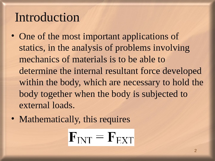
 2 Introduction • One of the most important applications of statics, in the analysis of problems involving mechanics of materials is to be able to determine the internal resultant force developed within the body, which are necessary to hold the body together when the body is subjected to external loads. • Mathematically, this requires
 3 • Objectives: i. Determine the characteristics of external forces. ii. Develop a technique to analyze the resultant internal forces within the body. iii. Learn how to apply shear and moment equations and plot the resultant forces. iv. Know the relationship between distributed load, shear and moment
 4 External Forces • In reality, the structures under investigation may be subjected to very complicated loadings in a form of distribution. • How is it possible to reduce a very complicated external loading to a characteristics or equivalent loading.
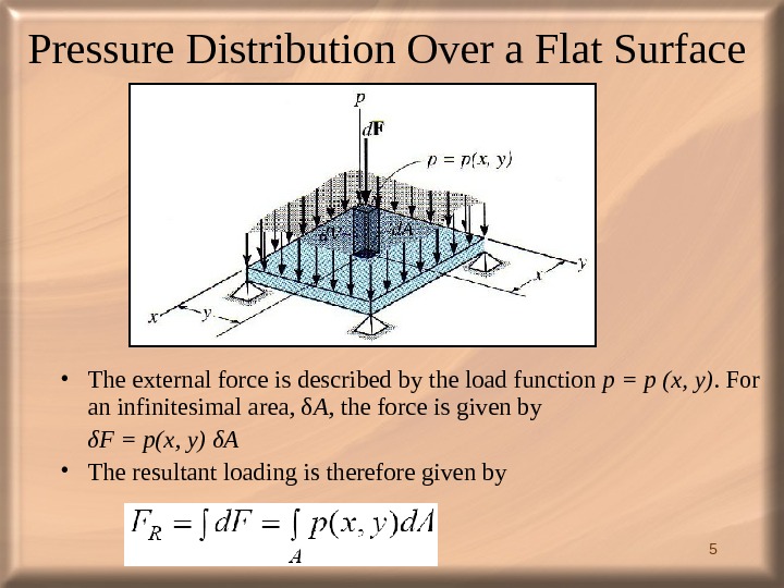
 5 Pressure Distribution Over a Flat Surface • The external force is described by the load function p = p (x, y). For an infinitesimal area, δ A , the force is given by δF = p(x, y) δA • The resultant loading is therefore given by
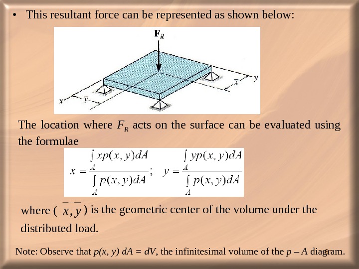
 6 • This resultant force can be represented as shown below: The location where F R acts on the surface can be evaluated using the formulae where (y, x ) is the geometric center of the volume under the distributed load. Note: Observe that p(x, y) d. A = d. V , the infinitesimal volume of the p – A diagram.
 7 • Pressure distribution can be caused by wind, fluid, weights of objects etc. • The intensity of the pressure distribution is measured in SI as N/m 2. • In Imperial System, it is measured in lb/ft 2 (psf) or lb/in 2 (psi). • Sometimes, kips is used for kilo-pound per sq. inch.
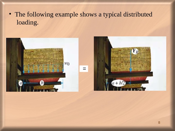
 8 = • The following example shows a typical distributed loading.
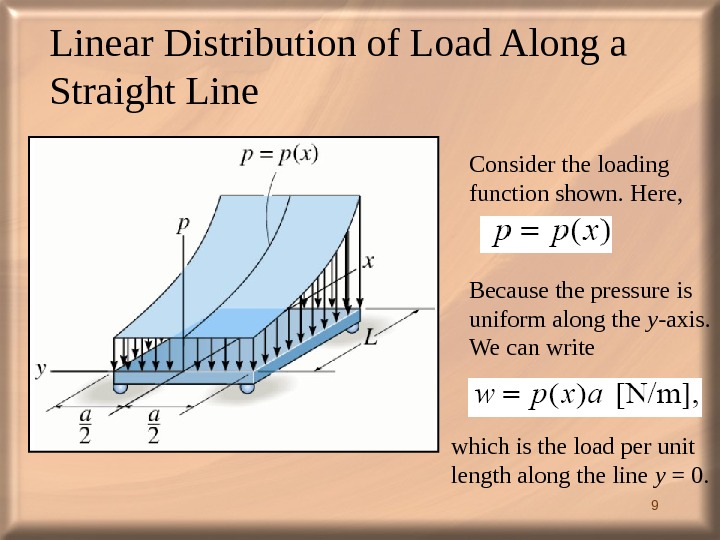
 9 Linear Distribution of Load Along a Straight Line Consider the loading function shown. Here, Because the pressure is uniform along the y -axis. We can write which is the load per unit length along the line y = 0.
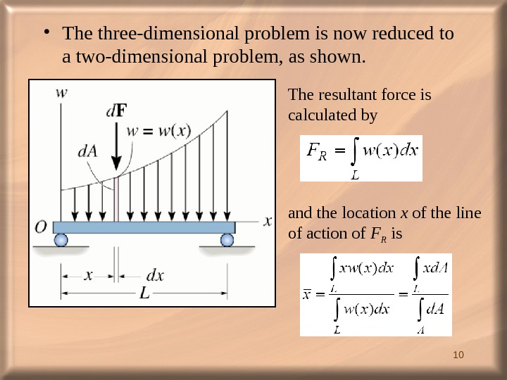
 10 • The three-dimensional problem is now reduced to a two-dimensional problem, as shown. The resultant force is calculated by and the location x of the line of action of F R is
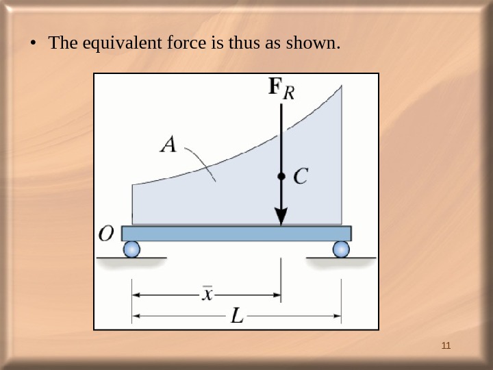
 11 • The equivalent force is thus as shown.
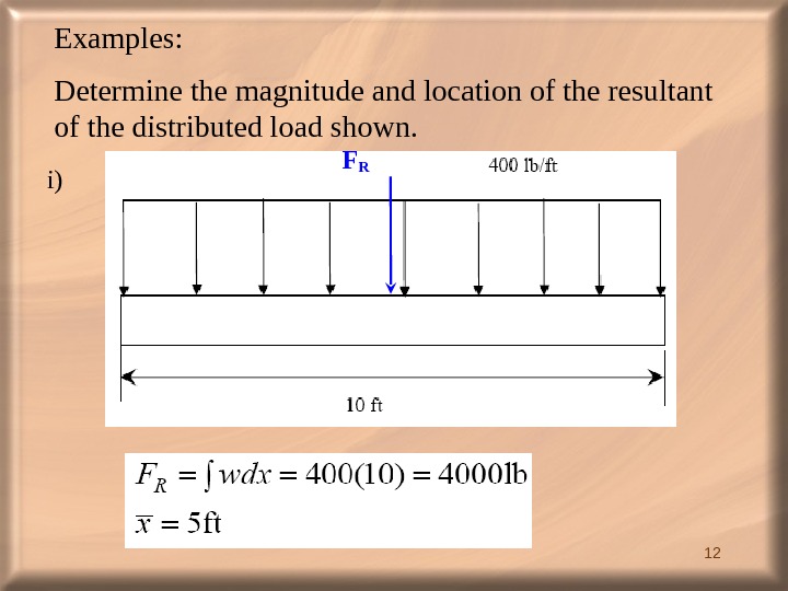
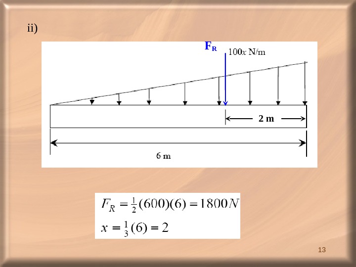
 12 Examples: Determine the magnitude and location of the resultant of the distributed load shown. FR i)
 13 FRii) 2 m
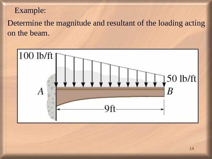
 14 Example: Determine the magnitude and resultant of the loading acting on the beam.
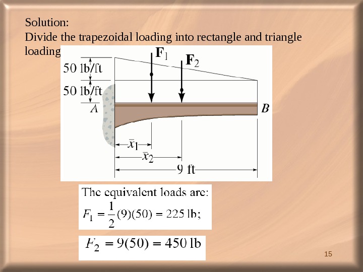
 15 Solution: Divide the trapezoidal loading into rectangle and triangle loading.
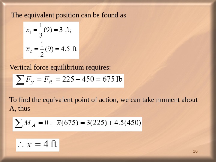
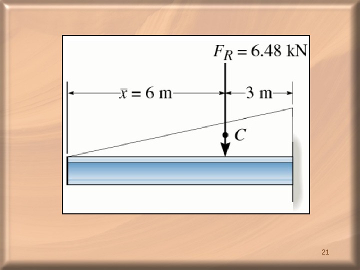
 16 The equivalent position can be found as Vertical force equilibrium requires: To find the equivalent point of action, we can take moment about A, thus
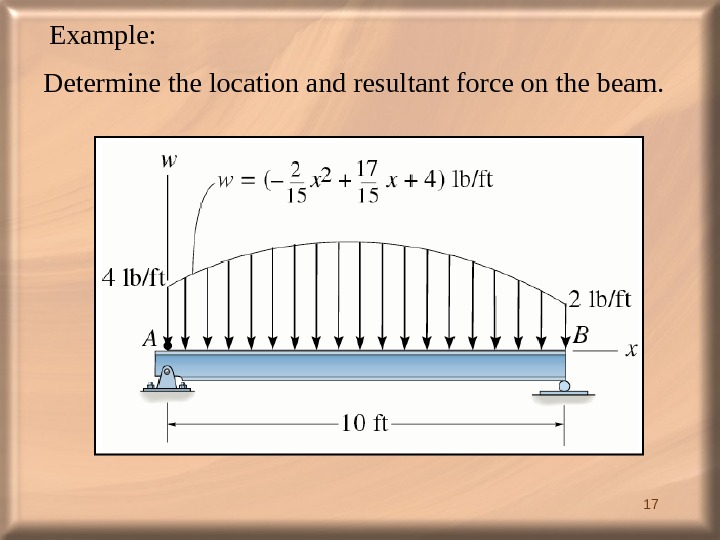
 17 Example: Determine the location and resultant force on the beam.
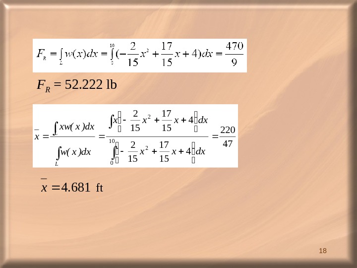
 18 F R = 52. 222 lb 47 220 4 15 17 15 2 10 0 2 2 dxxxx dx)x(w dx)x(xw x L L 6814. x ft
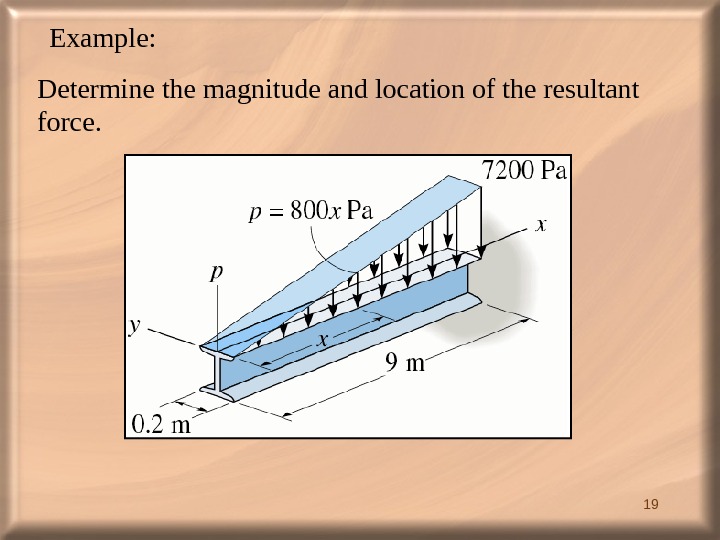
 19 Example: Determine the magnitude and location of the resultant force.
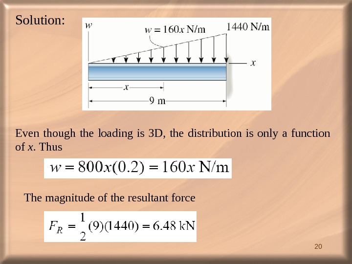
 20 Solution: Even though the loading is 3 D, the distribution is only a function of x. Thus The magnitude of the resultant force

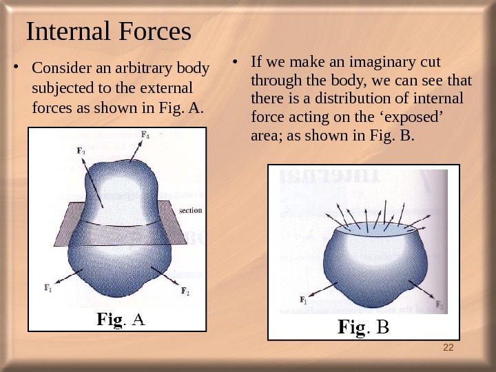
 22 Internal Forces • Consider an arbitrary body subjected to the external forces as shown in Fig. A. • If we make an imaginary cut through the body, we can see that there is a distribution of internal force acting on the ‘exposed’ area; as shown in Fig. B.
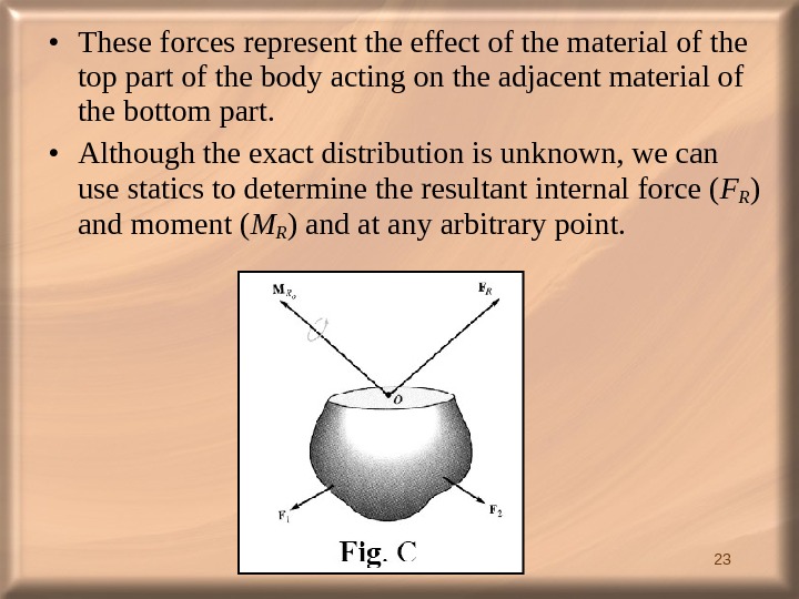
 23 • These forces represent the effect of the material of the top part of the body acting on the adjacent material of the bottom part. • Although the exact distribution is unknown, we can use statics to determine the resultant internal force ( FR ) and moment ( M R ) and at any arbitrary point.
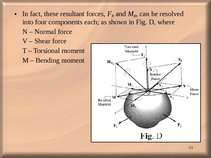
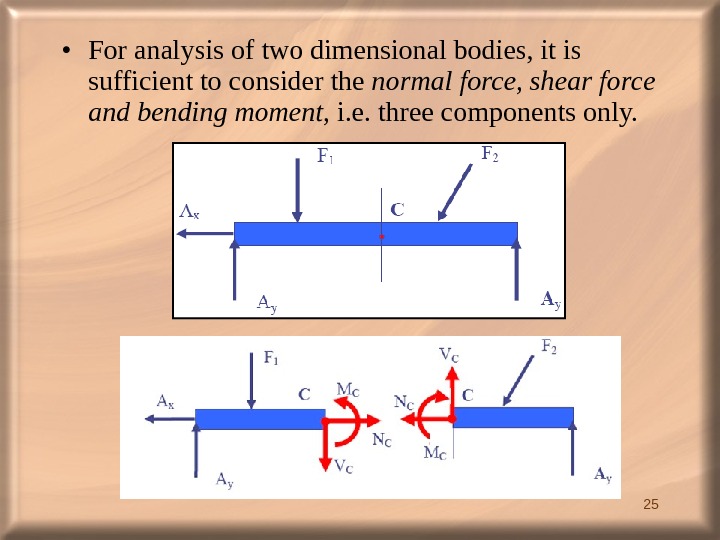
 24 • In fact, these resultant forces, FR and MR , can be resolved into four components each; as shown in Fig. D, where N – Normal force V – Shear force T – Torsional moment M – Bending moment
 25 • For analysis of two dimensional bodies, it is sufficient to consider the normal force, shear force and bending moment , i. e. three components only.
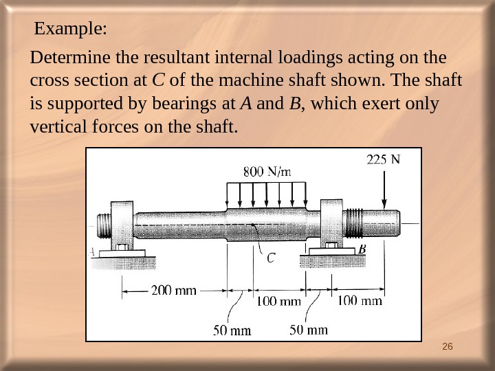
 26 Example: Determine the resultant internal loadings acting on the cross section at C of the machine shaft shown. The shaft is supported by bearings at A and B , which exert only vertical forces on the shaft.
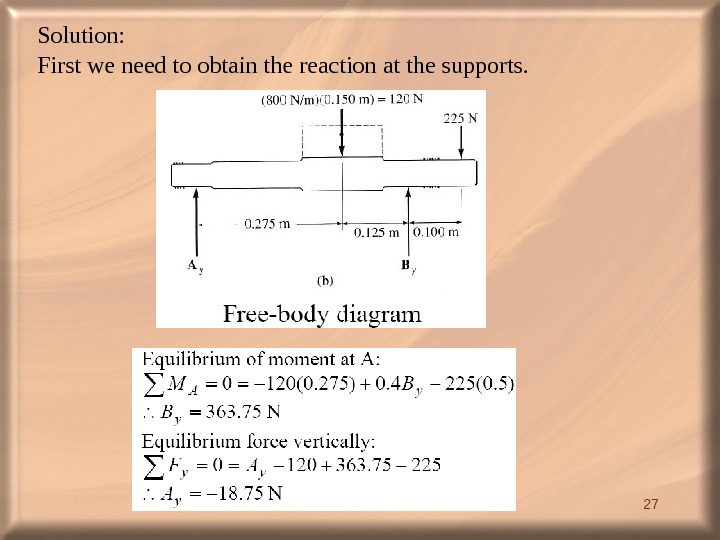
 27 Solution: First we need to obtain the reaction at the supports.
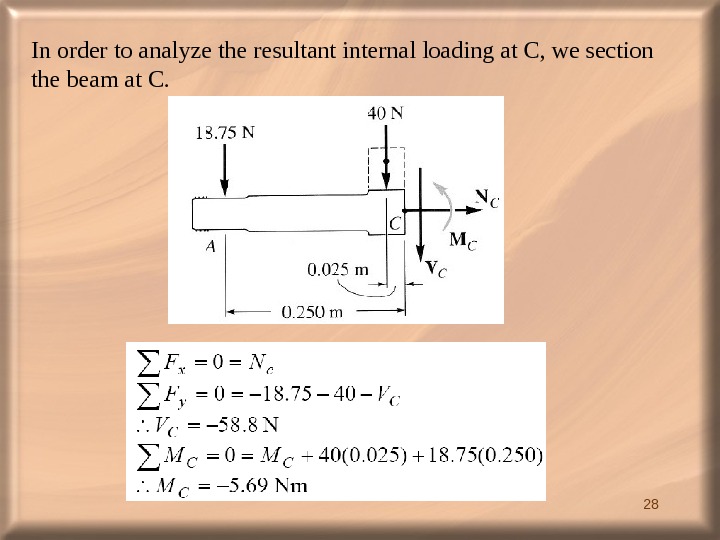
 28 In order to analyze the resultant internal loading at C, we section the beam at C.
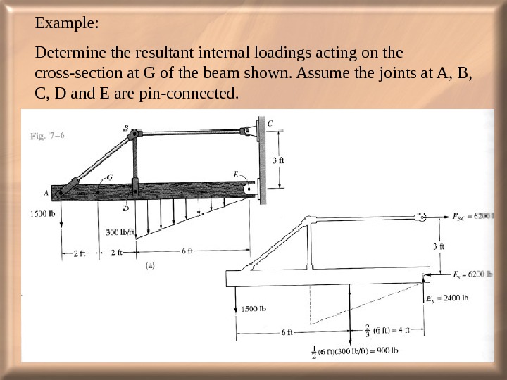
 29 Example: Determine the resultant internal loadings acting on the cross-section at G of the beam shown. Assume the joints at A, B, C, D and E are pin-connected.
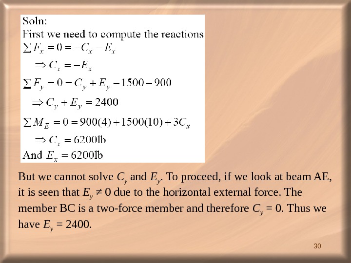
 30 But we cannot solve C y and E y. To proceed, if we look at beam AE, it is seen that E y ≠ 0 due to the horizontal external force. The member BC is a two-force member and therefore C y = 0. Thus we have E y = 2400.
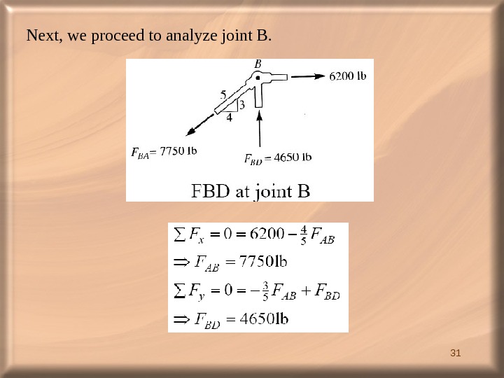
 31 Next, we proceed to analyze joint B.
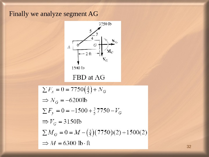
 32 Finally we analyze segment AG
 Extra Example Characteristics of External Loading
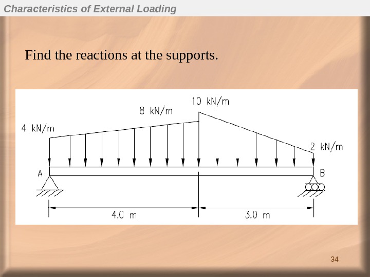
 34 Find the reactions at the supports. Characteristics of External Loading
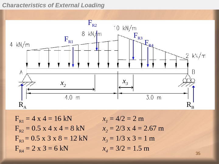
 35 F R 1 F R 2 F R 3 F R 4 x 2 x 3 F R 1 = 4 x 4 = 16 k. N x 1 = 4/2 = 2 m F R 2 = 0. 5 x 4 = 8 k. N x 2 = 2/3 x 4 = 2. 67 m F R 3 = 0. 5 x 3 x 8 = 12 k. N x 3 = 1/3 x 3 = 1 m F R 4 = 2 x 3 = 6 k. N x 4 = 3/2 = 1. 5 m. R A R BCharacteristics of External Loading
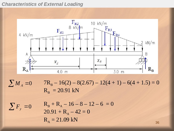
 360 AM 0 y. F 7 R B – 16(2) – 8(2. 67) – 12(4 + 1) – 6(4 + 1. 5) = 0 R B = 20. 91 k. N R B + R A – 16 – 8 – 12 – 6 = 0 20. 91 + R A – 42 = 0 R A = 21. 09 k. NCharacteristics of External Loading

