

c932bb90c147ed70693f7603fa2a0307.ppt
- Количество слайдов: 25
 INDUSTRIAL ELECTRONICS CONTROL EET 425/4 Lecturers Indra Nisja Anayet Karim School of Electrical System Engineering Northern Malaysia University College of Engineering
 CHAPTER 1 Introduction to Industrial Electronics Control The control of automated systems may be: electronic, mechanical, hydraulic, or pneumatic. In many instances, combinations of these types of control are used. The Reason For Using Industrial Automatic Control n n n n Reduced overall manufacturing costs Computational capabilities Fast response time Reduced equipment size and cost Environmental safety for operating personnel Prompt emergency recognition and reaction General convenience
 LEVELS OF INDUSTRIAL CONTROL
 Level 1 is the machine level. An example is a lathe with manual controls for moving the cutter through its path. Level 2 can be divided into three sublevels as shown in Figure 1 -1. Suppose an electronic, computer-based control operated the lathe. Such a control for automatic feed rate for cutting the metal would be level 2 A. This level 2 A rate would be automatically set for each part machined.
 Level 2 B is reached when controls are programmed for machining more than one part. The control pattern for each part is called up from a master control as required. The master control has been preprogrammed for each part. Level 2 C, is programmable control. At level 2 C the machining pattern for each part is programmed in by an operator. When a part’s machining program is first used, each step and motion are recorded as the process progresses.
 Level 3 involves connecting the control of two or more individual machines or devices to work together. An example of this level is controlling a robot to load a lathe as well as controlling the lathe’s operation. Level 4 of automatic control involves a number of work cells hooked up to a master, coordinating automatic computer control. The entire factory is under the control of a large master computer.
 INDUSTRIAL CONTROL CLASSIFICATIONS - Motion and Process Controls - Open- and Closed-Loop Systems n. A motion control system is an automatic control system that controls the physical motion or position of an object.
 There are three characteristics that are common to all motion control systems. - First, motion control devices control the position, speed, acceleration, or deceleration of a mechanical object. - Second, the motion or position of the object being controlled is measured. - Third, motion devices typically respond to input commands within fractions of a second, rather than seconds or minutes, as in process control. Hence, motion control systems are faster than process control systems.
 Process Control In process control, one or more variables are regulated during the manufacturing of a product. These variables may include temperature, pressure, flow rate, liquid and solid level, p. H, or humidity. Process control systems are divided into two categories, batch and continuous. Batch Process: Batch processing is a sequence of timed Operations executed on the product being manufactured. An example is an industrial machine that produces various types of cookies, as shown in Figure 1 -2
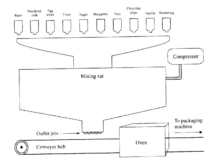
 Suppose that chocolate-chip cookies. First, the oven is turned on to the desired temperature. Next, the required ingredients in proper quantities are dispensed into the sealed mixing chamber. A large blender then begins to mix the contents. After a few minutes, vanilla is added, and the mixing process continues. After a prescribed period of time, the dough is the proper consistency, the blender stops turning, and the compressor turns on to force air into the mixing chamber. When the air pressure reaches a certain
 point, the conveyor belt turns on. The pressurized air forces the dough through outlet jets onto the belt. The dough balls become fully baked as they pass through the oven. The cookies cool as the belt carries them to the packaging machine.
 Continuous Process In: In the continuous process category, one or more operations are being informed as the product is being passed through a process. Producing paper, as shown in Figure 1 -3, is an example of continuous process.
 Figure 1 -3: A Pulp and Paper Operation is a Process Control Application
 Water, temperature, and speed are constantly monitored and regulated as the pulp is placed on screens, fed through rollers, and gradually transformed into a finished paper product. The continuous process can last for hours, days, or even weeks without interruption. OPEN- AND CLOSED-LOOP SYSTEMS n Open-Loop Systems: An open-loop system is the simplest way to control a system. A tank that supplies water for an irrigation system can be used to illustrate an open-loop (or manual control) system.
 n Figure 1 -4: An open-loop reservoir system that stores water for an irrigation system
 Closed-Loop Systems: The reservoir system can also be used to illustrate a closed-loop operation. To perform automatic control, the system is modified by replacing the manually controlled valve with an adjustable valve connected to a float, as shown in Figure 1 -5.
 n FIGURE 1 -5: A closed-loop system that uses a linkage mechanism as a feedback device to provide self-correcting capabilities
 ELEMENTS OF OPEN- AND CLOSED-LOOP SYSTEMS Controlled Variable. The controlled variable is the actual variable being monitored and maintained at a desired value in the manufacturing process. Measured Variable. To monitor the status of the controlled variable, it must be measured. Measurement Device. The measurement device is the “eye” of the system. It senses the measured variable and produces an output signal that represents the status of the controlled variable.
 Feedback Signal, the feedback signal is the output of the measurement device. Set Point. The set point is the prescribed input value applied to the loop that indicates the desired condition of the controlled variable. Error Detector. The error detector compares the set point to the feedback signal. Controller. The controller is the “brain” of the system. It receives the error signal (for closed-loop control) as its input, and develops an output signal that causes the controlled variable to become the value specified by the set point.
 Actuator. The actuator is the “muscle” of the system. It is a device that physically alters some type of energy or fuel supply, causing the controlled variable to match the desired set point. Manipulated Variable. The amount of fuel or energy that is physically altered by the actuator is referred to as the manipulated variable. Manufacturing Process. The manufacturing process is the operation performed by the actuator to control a physical variable, such as the motion of a machine or the processing of a liquid.
 Disturbance. A disturbance is a factor that upsets the manufacturing process being performed, causing a change in the controlled variable. In the reservoir system, the disturbances are the rainfall and evaporation that alter the water level.
 FIGURE 1 -6: Closed-loop block diagram that shows elements, input/output signals, and signal direction
 FIGURE 1 -7: Open-loop block diagram that shows elements, input/output signals, and signal direction
 FEEDBACK CONTROL Industrial automated control is performed using closed-loop systems. The term “loop” is derived from the fact that, once the command signal is entered, it travels around the loop until equilibrium is restored. The basic concept of feedback control is that an error must exist before some corrective action can be made. An error can develop in one of three ways: The set point is changed. A disturbance appears. The load demand varies.