 Ice & Rain protection Группа: Дав-12. 2

 BOEING 737 SYSTEMS PREVEW ICE & RAIN Protection 1. GENERAL ¡ The systems provided for ice and rain protection are Thermal Anti-icing (TAI) & electrical anti-icing. ¡ All 737 Classics pitot-static probes, 737 NG pitot probes, the Total Air Temperature probe, the 737 Classics angle of airflow sensors and 737 NG alpha vanes are electrically heated to prevent the formation of ice. Static ports are not heated.
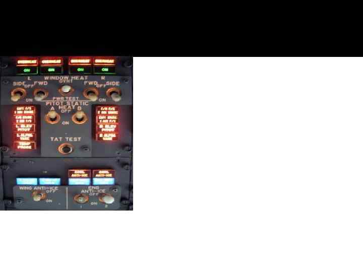
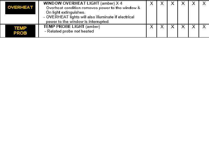
 Window If window heat is switched ON but the ON light is extinguished, this means that heat is not being applied to the associated window. This could be because the heat controller has detected that the window is becoming overheated (normal on hot days in direct sunlight) and can be verified by touching the window. The heat will automatically be restored when the window has cooled down. To verify that window heat is still available a PWR TEST should illuminate all ON lights if the window heat switches are ON. The PWR TEST forces the temperature controller to full power but overheat protection is still available. If an OVERHEAT light illuminates, either a window has overheated or electrical power to the window has been interrupted. The affected window heat must be switched OFF and allowed 2 -5 mins to cool before switching ON again. The OVHT TEST simulates an overheat condition.
 2. COCKPIT WINDOWS ¡ The cockpit windows are provided with electrical heating for antiicing and defogging. ¡ Heating the windows No. 1 and No. 2 also improves the impact strength of the windows for bird-strike protection. ¡ Air from the air-conditioning system can be used to defog the No. 1 cockpit windows. ¡ The windows No. 1 & No. 2 consist of glass panes laminated to each side of a vinyl core. The inner glass pane is the primary load carrying member. The vinyl core also acts as a backup load carrying member. The outer pane has no structural significance but provides a scratch resistant surface. A conductive coating on the outer pane permits electrical heating to prevent ice build-up and window fogging. B 737 NG : A permanent rain repellent coating is applied to the windows.
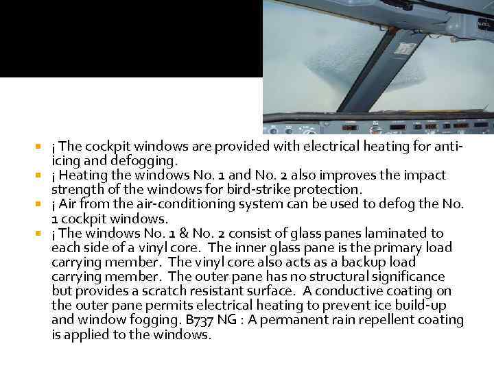 ¡ The cockpit windows are provided with electrical heating for antiicing and defogging. ¡ Heating the windows No. 1 and No. 2 also improves the impact strength of the windows for bird-strike protection. ¡ Air from the air-conditioning system can be used to defog the No. 1 cockpit windows. ¡ The windows No. 1 & No. 2 consist of glass panes laminated to each side of a vinyl core. The inner glass pane is the primary load carrying member. The vinyl core also acts as a backup load carrying member. The outer pane has no structural significance but provides a scratch resistant surface. A conductive coating on the outer pane permits electrical heating to prevent ice build-up and window fogging. B 737 NG : A permanent rain repellent coating is applied to the windows.
 4. WINDSHIELD WIPERS ¡ The windshield wipers are designed for use during takeoff, approach, and landing. ¡ Windshield wipers are provided to maintain a clear area on the cockpit No. 1 windows during takeoff, approach and landing, in rain or snow. Windshield wipers should not be used on a dry windshield. ¡ Each wiper is operated by a separate system to ensure that clear vision through one of the windows is maintained in the event of a system failure. ¡ Both wiper systems are electrically operated and controlled 737 Classics : by a common switch, 737 NG: by separate switches located on the overhead panel. The switch(es) provide(s) a selection of speeds and control(s) the stowing of the wiper blades in a PARK position when the system is not in use
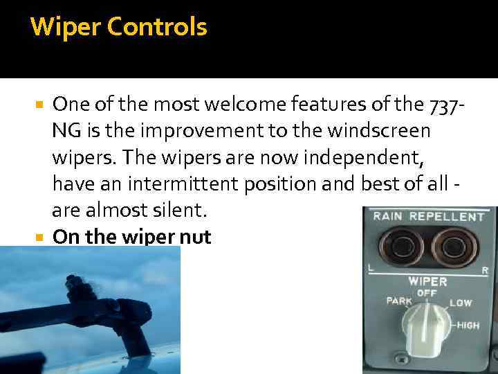 Wiper Controls One of the most welcome features of the 737 NG is the improvement to the windscreen wipers. The wipers are now independent, have an intermittent position and best of all - are almost silent. On the wiper nut
 Pitot Heat 3. ANGLE OF ATTACK SENSOR Contents Probes Static source selector Static ports Elevator pitot TAT probes ¡ Two 737 Classics Angle-Of Airflow sensors, 737 NG Alpha Vanes are installed on the forward fuselage. They provide angle-of-attack information to the stall warning system, autopilot, autothrottle and auto slats. They are anti-iced by heating elements, controlled by the Pitot Static Heat Switches.
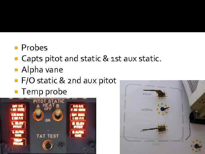 Probes Capts pitot and static & 1 st aux static. Alpha vane F/O static & 2 nd aux pitot Temp probe
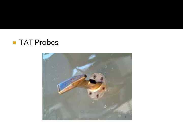 TAT Probes
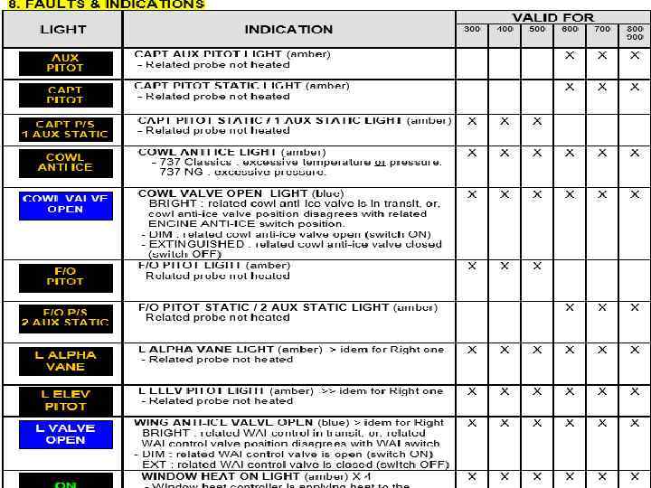
 5. ENGINE THERMAL ANTI-ICE ¡ Engine bleed air thermal anti-icing is provided for ice protection of the wing leading edge slats and engine cowl lip. On 737800/900, the outboard leading edge slats are not anti-iced. ¡ Engine anti-ice operation is controlled from the cockpit by individual Engine Anti-ice Switches. The engine anti-ice system may be operated on ground and in flight. ¡ Positioning the Engine Anti-Ice Switches ON sends an open signal to the engine cowl anti-ice valves and to the main engine control. ¡ Each cowl anti-ice valve is electrically controlled and pressure actuated. An open cowl anti-ice valve permits the cowl leading edge to be anti-iced by engine bleed air. ¡ If there is a disagreement between the anti-ice switch and the cowl anti-ice valve position, the COWL VALVE OPEN Light remains illuminated bright blue and 737 NG an amber TAI indication is displayed above the engine N 1 indication
 6. WING ANTI-ICE General ¡ The wing anti-ice system provides protection for the leading edge slats by using bleed air from the main pneumatic manifold. The system does not include the leading edge flaps and 737 NG outboard slats. ¡ The wing anti-ice control valves are AC motor operated. Valve position is monitored by the blue Valve Open Lights. With a valve open, bleed air flows through the wing distribution duct in the leading edge, through a telescoping duct to each slat, and is then exhausted overboard. The wing anti-ice system is effective with the slats in any position.
 Ground-Enabled Wing Anti-ice ¡ On ground, positioning the WING ANTI-ICE Switch ON opens the wing anti-ice control valves if thrust on both engines is below the setting for take-off warning activation and provided the temperature in the distribution duct does not exceed a certain limit. ¡ Both valves close if thrust increases above the takeoff warning setting or in case of overheat, however, the switch remains in the ON position. If thrust or temperature is reduced, the valves re- open automatically. The switch trips to OFF at liftoff. ¡ The terminal switches and thrust setting logic are disabled in flight.
 Wing Anti-ice operation in flight ¡ Positioning the WING ANTI-ICE switch to ON in flight : - opens both control valves - sets stick shaker logic for icing conditions.
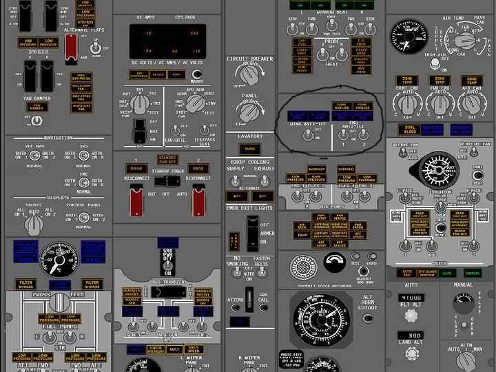
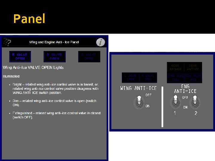 Panel
Panel
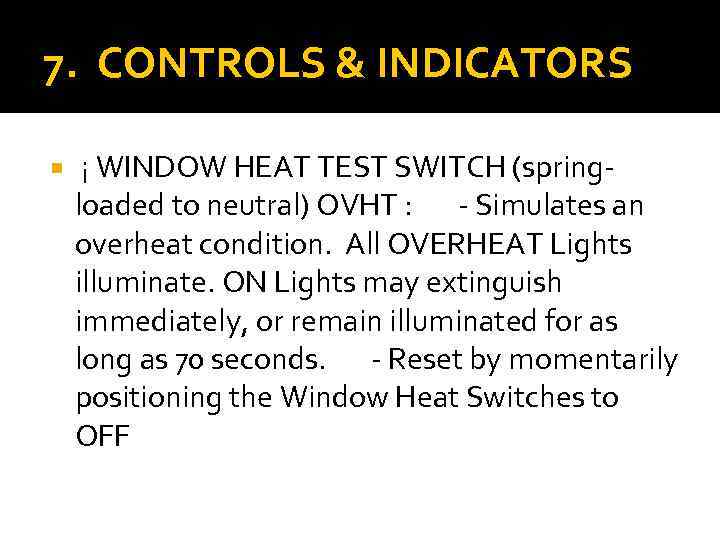 7. CONTROLS & INDICATORS ¡ WINDOW HEAT TEST SWITCH (springloaded to neutral) OVHT : - Simulates an overheat condition. All OVERHEAT Lights illuminate. ON Lights may extinguish immediately, or remain illuminated for as long as 70 seconds. - Reset by momentarily positioning the Window Heat Switches to OFF
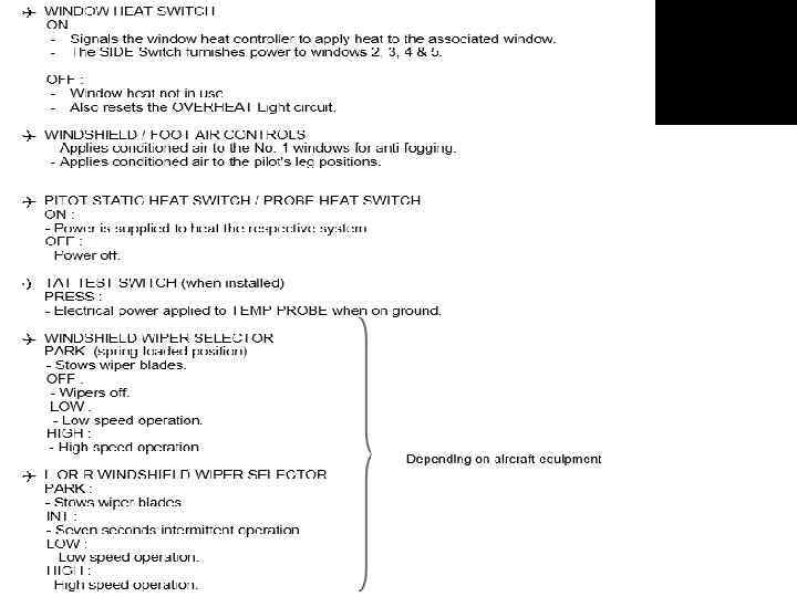
 ENGINE ANTI-ICE SWITCH ON : - Opens corresponding engine anti-ice valve and illuminates the COWL VALVE OPEN light. Engine anti-ice valve closes and the COWL VALVE OPEN light extinguishes. ¡ WING ANTI-ICE SWITCH (Ground inhibited wing anti-ice) OFF : - Wing anti-ice control valves are closed. - VALVE OPEN Lights are extinguished. ON (in flight) : - Wing anti-ice control valves are open. - VALVE OPEN lights illuminated dim. ON (on ground) : - Air/Ground sensor prevents Wing Anti-Ice control valves from opening. GRD TEST (momentary position) : - Opens wing anti-ice control valves when on the ground. - If duct temperature exceeds a preset limit during test, wing anti-ice control valves close.
