bf10a88aa19939083de55c23f10d28a9.ppt
- Количество слайдов: 33


http: //www. scrbg. org/
 Frequency Callsign Output EIRP")
The GB 3 SC# Microwave Beacons What we have (now) Frequency Callsign Output EIRP 2320. 905 MHz GB 3 SCS 3 Watts 3400. 905 MHz GB 3 SCF 6 Watts 5760. 905 MHz GB 3 SCC 10 Watts 10368. 905 MHz GB 3 SCX 18 Watts GPS Locked, RTTY Data 24048. 905 MHz GB 3 SCK 5 watts Started on 24192. 905 47088. 905 MHz G 8 BKE/P 200 m. W Directional, Turned on when needed 70. 031 G 4 JNT/P 500 m. W Slow. CW Telemetry <= 100 m. W 802. 11 b WLAN Link 2. 4 GHz --- Notes GPS Locked, RTTY Data

South Coast Beacon Complex l l l Had been operational on the Purbecks Good site for GB 3 SCX and we just about had 3. 4 GHz running QRP Starting to install others. Kicked off site by mobile phone operators So, we needed a new site…………. . G 0 API GB 3 SCX

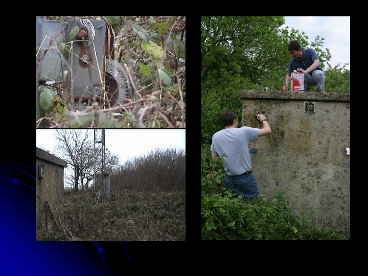
Bell Hill Loc IO 80 UU 59 l l Used for contesting by FRARS for years Unused Versatower and cabin – it had mains power Rusty fittings, but all in a useable condition So we took over the site in 2001 –

Good take off in most directions

Hut Preparation Had been an animal shelter l Need to prevent condensation l Limit temperature extremes l l Walls and door covered in polystyrene l All holes and gaps blocked

Temperature Plots

Mast Renovation l l l Needed a lot of work Four sets of Guys and stakes New Haul and luffing ropes. l l Old haul rope broke when winching down New one had to be installed in-situ Everthing stripped down and soaked in diesel Anti-rust paint Old PMR Antenna jammed in winch mechanism

Cable Support Five 12 metre runs of LDF 4 -50 plus lightning + spare. l Too heavy to self hang from top l Mid point cable support – ‘revolver breech’ supported from pulley l

Cable hoops prevent swinging l Cables can’t be bound together or harness could never be moved ! l Duct at lower end into hut l

DON’T DO THIS AT HOME !

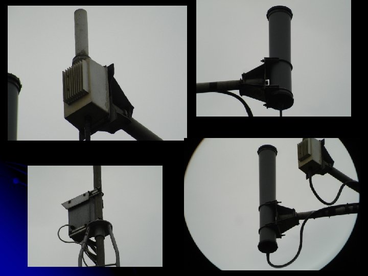
The Head assembly Need to survive high winds l Mounted on scaffold across tower faces l

Antenna Range Tests All antennas mounted close together l Tests needed to see if there were interactions / gaps in coverage l Antenna test range from G 0 API driveway to a neighbour across the road – just in far field but with no Fresnel zones l Showed we had a workable system l But……. l

`

Tests and Measurements l Alford slots weren’t doing their job properly l Field distribution along the slot was wrong l Needed small diameter l One coax was much lossier than expected l Fault in coax connector - ¼ wavelength suckout at 12 GHz (for 24 GHz, GB 3 SCK)

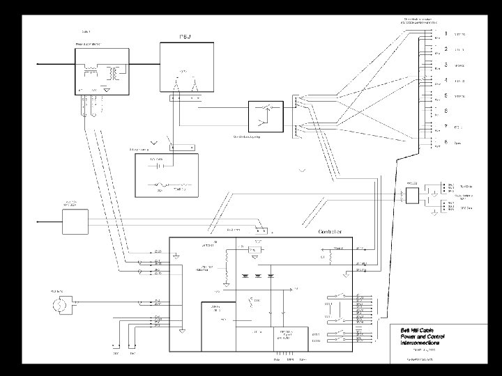
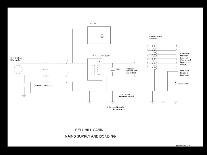
Power Supplies l Mains cable 1 km long, 1. 5 mm 2 armoured l 23 ohms loop resistance l 750 Watts absolute maximum (2. 5 k. W Kettle = Zo) 260 W for beacons and PC = 190 to 210 V input. Switch Mode PSU essential l All beacons run from 12 V battery floated across PSU - 10 Amps total l PC has its own UPS l

Mains Failure l l Extended mains or PSU failure could flatten battery – one 24 Ah battery lost already Two levels of protection added l Software puts beacons to standby immediately if mains goes off or DC drops below charge voltage l l l 3 A to keep oscillators, ovens and TLM active, 8 to 10 hours Then a hardware shut-off if DC drops below 10 V Small auxilliary PSU for TCmd/TLM, crossstrapped, allows for failure of sensing unit / main PSU.

Earthing / Protection l l l Problems with lightning on an exposed hilltop Tower metalwork has poor bonding – dedicated conductor up mast for high E-fields Nearby ground strikes are the biggest problem All metalwork in hut, rack mount, firmly bonded to feeders, mains cable sheath and extensive array of ground radials / rods in 10 m circle around the cabin Everything jumps together Varistors were fitted on the mains input after a nearby strike took out the PSU last June

Remote Control l l l Distant site – no quick access for the nominated keepers (30 – 80 km trip) – one local op. G 7 RMG Radio controlled link, Bi-directional, 70 cm FM, allows verification of commands. T 7 F transceiver module PIC Based controller with own battery back up. DTMF tones for control from handie-talkie using rolling set of 5 digit access codes for security. Three PIN tables for different users l Position in code table accessible on command l Status of each circuit on/off state can be requested Switches 8 circuits on/off via relays with isolated contacts

Telemetry l l l l Dedicated PIC based TLM monitor with A/D converters Mains Voltage / Current, DC Volts, Temperatures, Status Switches Originally just sent CW when demanded on UHF link. Later, 70 MHz low power Tx (G 4 JNT/P) sending basic parameters as CW / Slow. CW PC logging data via RS 232 link from monitor 18 km WLAN link and webserver Possibility for alarms sent to users by text message / Email. Video link
")
47 GHz turned on (We know what you’re doing, Chris and John !)

Frequency Locking ‘Simple GPSDO’ on site, supplying 10 MHz with typical 10 -9 accuracy l GB 3 SCF and GB 3 SCX locked to this using DDS solution – others to follow l 10368. 9050068 MHz (32 bit DDS) l 3400. 90499999985 MHz (48 bit DDS) l But only to GPSDO accuracy! l

Equipment rack
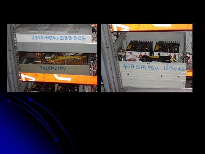

Beacon Head Units Inside the Beacon Hut GB 3 SCS GB 3 SCF GPS Locked 10 MHz Reference GB 3 SCC GB 3 SCX UHF Command Telemetry Module GB 3 SCK Power Monitor Switching Relays Mains Supply UHF Antenna 12 V 30 A PSU 25 A-Hour Pb/H+ Battery Mast

GB 3 SCF with frequency locked source

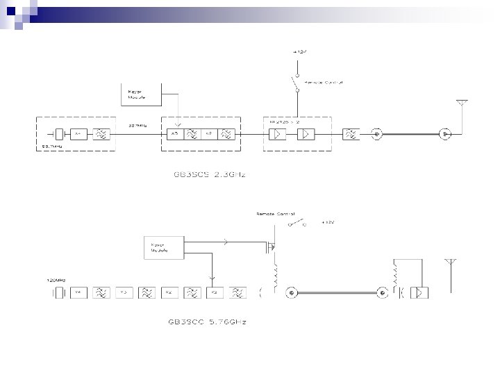
+12 V DDK 004 Source Module 324 MHz 108 MHz X 3 1. 3 GHz 648 MHz X 2 2. 6 GHz X 2 Bandpass Crystal Multiplier filter Oscillator Head Unit LDF 450 Feed to Masthead Slotted Waveguide Antenna X 4 Block Diagram of GB 3 SCX (the original version before frequency locking) 10. 368 GHz Power Amplifier

70 MHz Dipole Cable Duct into cabin 47 GHz
bf10a88aa19939083de55c23f10d28a9.ppt