

7eaaa95820348bbdd3d876eaa1442f57.ppt
- Количество слайдов: 41
 Hokie. Sat Introduction Daniel Pedraza Systems & Operations Hokie. Sat dpedraza@vt. edu 22 August, 2002
 Overview 1. Introduction 2. Mission & System Overview 3. 3 CS Mission 4. ION-F Mission 5. Design/Configuration 6. Structure/Mass 7. Propulsion 8. Testing
 – “Tech. Sat-21” •") Mission and System Overview • Air Force Research Laboratory (AFRL) – “Tech. Sat-21” • Investigate small, distributed spacecraft systems • Missions of larger, single platforms • University Nanosatellite Program (UNP) – Purpose: • help explore and implement technologies of small satellites • 10 schools
Mission and System Overview • Air Force Research Laboratory (AFRL) – “Tech. Sat-21” • Investigate small, distributed spacecraft systems • Missions of larger, single platforms • University Nanosatellite Program (UNP) – Purpose: • help explore and implement technologies of small satellites • 10 schools
 Participating Universities Nanosat-1 Nanosat-2 Emerald Orion ION-F 3 -Corner Sat
 Mission and System Overview • VT-ISMM – Virginia Tech Ionospheric Scintillation Measurement Mission – Single satellite investigation – Design quickly integrated with: • Utah State University • University of Washington • VT-ISMM =====> ION-F
 Mission and System Overview • ION-F Formation Flying Mission – – – NASA-Goddard Space Flight Center (GSFC) Many algorithms developed at GSFC Earth Observer 1 (EO-1) flies with Landsat 7 Three (3) satellites with propulsive capabilities Demonstrate more involved formation flying routines
 Nanosat-2 Brief Milestone Schedule Dec 01 Sep 01 Jun 01 Mar 02 04 -06 April 01 CDR 25 May 01 (est. ) Phase 0/1 Safety Review Phase 2 Safety Package Development Phase 3 Safety Package Development 15 July 01 MSDS Fabrication 01 December 01 Nanosat Delivery Integration and Test
 University Nanosatellite Program Overview University Nanosatellites DESCRIPTION Nine U. S. universities are producing nine nanosatellites. The nanosats will be deployed via 2 flight missions from Space Shuttle SHELS hardware (Nanosat-1 and Nanosat-2) The nanosats are organized into 3 subclusters for the purposes of demonstrating formation flying, intersatellite collaborative processing/ communication, and autonomous control operations and data downlink Each nanosat cluster incorporates unique technology demonstrations and science measurement capabilities • Sponsors: Air Force Research Labs, NASA’s Goddard Flight Center AFRL Multi. Satellite Deployment System (MSDS) NASA Shuttle Hitchhiker Experiment Launch System (SHELS)
 3 CS Introduction/System Three Corner Sat Introduction/Systems Arizona State University New Mexico State University of Colorado at Boulder
 3 CS Mission • 3 universities working together to develop constellation of 3 identical satellites • ~2 year development schedule • Launched as stack on NASA Space Shuttle • Each university emphasizing its past heritage • Innovative, low-cost solutions & development encouraged
 3 CS Mission Objectives • Inter-satellite Communications • Virtual Formation Flying • Distributed & Automated Operations • Imaging • Modular, Generic Design • Micropropulsion Experiment • Student Education
 ION-F Introduction/Systems Virginia Tech University of Washington Utah State University
 ION-F Mission • Investigate satellite coordination and management technologies and distributed ionosphere scintillation measurements • Coordinate on satellite design, formation flying, management mission development, science instruments, mission • Design and implement internet-based operations centers, enabling each university to control its satellite from a remote location
 Mission Configuration: 3 CS ION-F USUSat Dawgstar Scenario: Hokie. Sat Multiple Satellite Deployment System
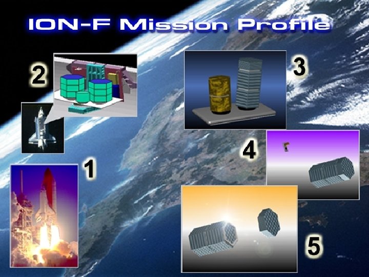
 Separation Scenarios
") Multiple Satellite Deployment System (MSDS)
Multiple Satellite Deployment System (MSDS)
 Leader / Follower Formation Orbit Ground Track
 Same Ground Track Formation Orbit Ground Track
 major diameter hexagonal prism •") Design Hokie. Sat • 18. 25” (~ 45 cm) major diameter hexagonal prism • 12” tall (30 cm) • 39 lbs (~18 kg) • Isogrid Structure • Composite Side Panels – 0. 23” isogrid – 0. 02” skins
Design Hokie. Sat • 18. 25” (~ 45 cm) major diameter hexagonal prism • 12” tall (30 cm) • 39 lbs (~18 kg) • Isogrid Structure • Composite Side Panels – 0. 23” isogrid – 0. 02” skins
 External Configuration Crosslink Antenna GPS Antenna Solar Cells Light. Band Pulsed Plasma Thrusters Data Port Camera Science Patches Downlink Antenna Uplink Antenna
 Camera Crosslink Components Power Processing Unit Magnetometer Pulsed") Internal Configuration Cameras Torque Coils (3) Camera Crosslink Components Power Processing Unit Magnetometer Pulsed Plasma Thrusters (2) Camera Battery Enclosure Rate Gyros (3) Downlink Transmitter Electronics Enclosure
Internal Configuration Cameras Torque Coils (3) Camera Crosslink Components Power Processing Unit Magnetometer Pulsed Plasma Thrusters (2) Camera Battery Enclosure Rate Gyros (3) Downlink Transmitter Electronics Enclosure
 VT Structures Overview
 Hokie. Sat Structure Panel 6 Panel 5 Panel 4 Panel 1 Panel 2 Panel 3 Nadir/Zenith Panel
 Hardware • Description: Nadir and Zenith • Heritage: None • Manufacturer: In-House/Techsburg • Properties: Al 6061 T-6, Class 3 Irridite (MILC-5541 -E) • Mass: 1. 70 lbm (0. 773 kg) • Status: Prototype Complete Ø 0. 190 x 3 Thru
") Mass Total Mass = 16. 6 lbm (7. 57 kg)
Mass Total Mass = 16. 6 lbm (7. 57 kg)
 Total Mass = 118. 8 lb (54 kg)") Mass Breakdown (Stack) Total Mass = 118. 8 lb (54 kg)
Mass Breakdown (Stack) Total Mass = 118. 8 lb (54 kg)
 Propulsion • Propulsion subsystem requirements • Schematic • VT thruster arrangement • System parameters • Operations summary
") Propulsion Subsystem Requirements • Provide thrust required for the formation flying mission (phase 1) – 22 m/s DV required • Orbit raising to extend life (phase 2) – Remaining propellant • Augment torque coils for yaw attitude control
Propulsion Subsystem Requirements • Provide thrust required for the formation flying mission (phase 1) – 22 m/s DV required • Orbit raising to extend life (phase 2) – Remaining propellant • Augment torque coils for yaw attitude control
 VT Thruster Arrangement Top View 1 2 3 4
 Schematic Spring Ultem 2300 Thruster Assembly Teflon Fuel Bar Mica-paper / Foil Capacitor Ultem Isolator Cathode Boron Nitride Insulator Anode Thruster mount
 System Parameters Power
 Interfaces • Structural – 4 thruster nozzle holes, sized and placed as defined in drawings – 2 thruster mounts, attached directly to isogrid nodes • Power – – Requires 13 watts at 28 volts for translation System can tolerate a decrease in voltage to 16. 5 volts No power required when system not in use Approximate duty cycle: • 3% formation keeping • 10% formation maneuvering
 Solar Cell • • • Tecstar Triple-Junction 24% Cascade cells Heritage on DS-1, Mighty. Sat, SMEX, TRACE, others Cell Dimensions: 2. 497” x 1. 522” (6. 25 x 3. 75 cm) 0. 030” spacing between cells Cells supplied kitted – Cover glass – Diode on each cell – Interconnects
 Fabrication Composite structure comprised of 0. 23” isogrid and 0. 02” skin
 Static Testing Strength & stiffness test of structure without skin panels Strength & stiffness test of loading fixture
 Static Testing Strength & stiffness test of structure with skin panels • Experiment demonstrated a 32% gain in stiffness in the cantilever mode due to addition of skins • Skins added less than 8% to the total mass
 Testing of Side Panels • Hammer provides impulsive input •") Dynamic Testing Modal (tap) Testing of Side Panels • Hammer provides impulsive input • Accelerometer measures accelerations used to characterize natural frequencies • Tap testing with and without skins • Verification of predictions of finite element analysis
Dynamic Testing Modal (tap) Testing of Side Panels • Hammer provides impulsive input • Accelerometer measures accelerations used to characterize natural frequencies • Tap testing with and without skins • Verification of predictions of finite element analysis
 Up-Link Antenna Pictures
 Clean Room Pictures
 Acknowledgements • Air Force Research Laboratory • Air Force Office of Scientific Research • Defense Advanced Research Projects Agency • NASA Goddard Space Flight Center • NASA Wallops Flight Facility Test Center • University of Washington • Utah State University • Virginia Tech • Professor A. Wicks • Professor B. Love • Members of ION-F AFOSR Goddard Space Flight Center STP Defense Advanced Research Projects Agency