
GROUP D – STRUCTURE ATA-chapter 51 / STANDARD


- Размер: 34.3 Mегабайта
- Количество слайдов: 56
Описание презентации GROUP D – STRUCTURE ATA-chapter 51 / STANDARD по слайдам
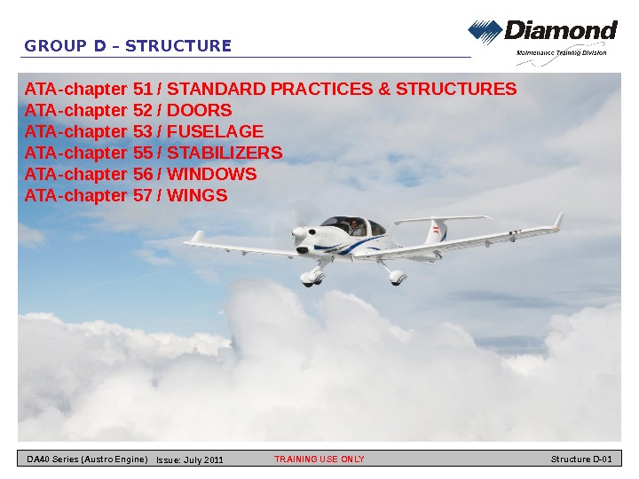
GROUP D – STRUCTURE ATA-chapter 51 / STANDARD PRACTICES & STRUCTURES ATA-chapter 52 / DOORS ATA-chapter 53 / FUSELAGE ATA-chapter 55 / STABILIZERS ATA-chapter 56 / WINDOWS ATA-chapter 57 / WINGS TRAINING USE ONLYDA 40 Series (Austro Engine) Structure D-01 Issue: July
ATA 51 – STANDARD PRACTICES & STRUCTURES TRAINING USE ONLY Structure D-02 DA 40 Series (Austro Engine) Issue: July
General The DA 40 NG is a single-engine, low-wing monoplane of composite construction. It has a ‘T’ tail and a fixed tricycle landing gear with a nose wheel that can caster. The DA 40 NG fuselage has a semi-monocoque structure. Two glass fiber reinforced plastic (GFRP) half-shells make the fuselage skin. The fuselage shells have many layers of glass cloth. Rigid foam inserts give stiffness to the fuselage shells where necessary. All of the main structural components are GFRP rigid moldings. Many layers of glass cloth bond together to make each molding. Some components have layers of carbon fiber cloth to give more strength and stiffness. The DA 40 NG has a cantilever wing. The wing has top and bottom shells. It has front and rear spars and a root rib made in three parts. Each shell has a carbon fiber reinforced plastic (CFRP) outer skin, a rigid foam core and a GFRP inner skin. The vertical stabilizer is part of the fuselage. The aft part of the left and right fuselage shells make the left and right shells of the vertical stabilizer. Each wing has two I-section spars. The front spar on one side is the same as the rear spar on the opposite side. Many layers of uni-direcitonal carbon fiber make the spar caps. The number of layers in the spar caps decrease from root to tip. Each spar has a shear web. The shear web has GFRP skins and a rigid from cor. Glass cloth fillets attach the spar caps to the shear web. A rear web closes the trailing edge of the wing. An end rib closed the outboard end of the wing. A removable GFRP tip attaches to the wing shells and outer rib with screws. The flaps and ailerons have top and bottom shells. Each shell has mixture of CFRP and GFRP cloth. The shells have rigid foam cores and bond together. The horizontal stabilizer has top and bottom shells. Each shell. Has GFRP skins. The horizontal stabilizer has a front spar and a rear spar. Three pairs of ribs give strength to the center area. The elevator has top and bottom shells. Each shell has GFRP skins with a rigid foam core. The rudder has left and right shells. Each shell has GFRP skins with a rigid foam core. The shells bond together at a flange. The canopy is a CFRP molding with inner and outer frames which bond together. The canopy has a large one-piece acrylic glass window. The passenger door is a CFRP molding with inner and outer frames. The frames bond together. The door has an acrylic glass window. A polyurethane paint finish protects the outside skin of the airplane from ultraviolet rays and humidity. ATA 51 – STANDARD PRACTICES & STRUCTURES TRAINING USE ONLY Structure D-03 DA 40 Series (Austro Engine) Issue: July
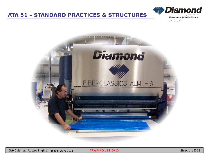
Types of Structure The DA 40 NG is constructed from 2 main types of composite structure. A. Glass Fiber Reinforced Plastic (GFRP) GFRP is very thin glass fibers bonded together by resin. The glass fibers give most of the strength and the resin maintains the shape. The resin also bonds to other structural components such as metal attachment brackets or metal bushings. The glass fibers are woven to make glass cloth. The orientation and weave of the glass in the cloth affects the structural strength of the cloth. A component can have many layers of cloth bonded together with resin. This is called lamination. GFRP has very good properties. It is strong and flexible. It is very resistant to chemical attack and very little maintenance is necessary. B. Carbon Fiber Reinforced Plastic (CFRP) CFRP is very thin carbon fibers bonded together by resin. The carbon gives most of the strength and the resin maintains the shape. The resin also bonds to other structural components such as metal attachment brackets or metal bushings. CFRP is very similar to GFRP. The main advantage of CFRP is that it is stronger and more rigid than GFRP. Laminated Components A laminated component has 2 or more layers of glass/carbon cloth. The direction of the fibers in the cloth give the properties for each layer. Extra layers are bonded to areas to gibe more strength. Sandwich Structure Many of the components in the DA 40 NG have a sandwich of 2 skins and a core. GFRP or CFRP make the skins and rigid plastic foam makes the core. The skins must bond to the core of a sandwich structure completely. If the skins do not bond to the core the component can fail. Bonded Components A number of components can bond together to make a larger component. Special thick resin bonds these components together and fills the gap in a joint. These thick resin is called “Bonding Paste” and have to be mixed as follows: ATA 51 – STANDARD PRACTICES & STRUCTURES TRAINING USE ONLY Structure D-04 DA 40 Series (Austro Engine) Issue: July
ATA 51 – STANDARD PRACTICES & STRUCTURES Repair Limitations Repair which are categorized as ‘Class 1’ in accordance with Section 51 -10, Paragraph 2, may only be carried out in accordance with a repair scheme which has been approved by the manufacturer. Such repairs are not described in the Airplane Maintenance Manual. Investigation General This Section tells you how to assess the class of the damage. It also tells you how to inspect glass fiber reinforced plastic (GFRP) and carbon fiber reinforced plastic (CFRP) composite structures. Damage assessment and repairs must be carried out by approved persons. Damage Classification Damage is divided into the classes described below. In doubtful cases (i. e. , if you are not sure about the classification of a damage), you must contact the airplane manufacturer. A. Class 1 — Major structural damage that requires the partial replacing of a structural component, or — damage to a large area, or — damage to a highly stressed component or part. This type of damage restricts or voids airworthiness. B. Class 2 Holes and cracks passing through both skins of a sandwich construction component. The core damage must be able to be covered by a 75 mm (3 inches) diameter circle. C. Class 3 Small holes or cracks in the outer skin where there is no internal damage to the component, the sandwich material, or the inner skin. D. Class 4 Minor scratches, abrasions or similar damage which is not a crack or a puncture in the skin. TRAINING USE ONLY Structure D-05 DA 40 Series (Austro Engine) Issue: July
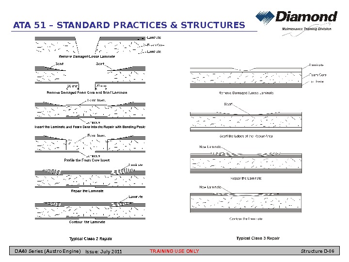
ATA 51 – STANDARD PRACTICES & STRUCTURES TRAINING USE ONLY Structure D-06 DA 40 Series (Austro Engine) Issue: July
ATA 51 – STANDARD PRACTICES & STRUCTURES Types of Damage There are 2 basic types of hidden failure in composite structures: • Disbonding. • Delamination. Disbonding is the failure of a bond between 2 components. For example between the fuselage skin and a fuselage frame. Or between a composite component and a metal component. Or between a composite skin and a sandwich core material. Delamination is the failure of the bond between layers of glass/carbon cloth in a component. There also 2 main types of cracks: • Micro cracks which occur in the surface of the resin. • Major cracks with broken fibers. Major cracks do not occur with normal flight loads or normal landing loads. You must repair major cracks. TRAINING USE ONLY Structure D-07 DA 40 Series (Austro Engine) Issue: July
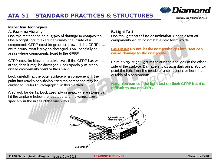
ATA 51 – STANDARD PRACTICES & STRUCTURES Inspection Techniques A. Examine Visually Use this method to find all types of damage to composites. Use a bright light to examine visually the inside of a component. GFRP must be green or brown. If the GFRP has white areas, then it may be damaged. Look specially at areas where components bond to the GFRP. CFRP must be black or black/brown. If the CFRP has white areas, then it may be damaged. Look specially at areas where components bond to the CFRP. Look carefully at the outer surface of a component. If the paint has cracks or bubbles, then the composite may be damaged. Refer to Paragraph 5 in this Section. Also look for dents. Look specially in areas where stones can hit the airplane below the fuselage and the wings. Look specially in the areas of the walkways. B. Light Test Use the light test to find delamination. Use this test on components which do not have rigid foam inside. CAUTION: Do not let the composite get hot. Heat can cause damage to the composite. Point a very bright light at the surface and look at the other side of the surface. Damage shows as a dark area. You can point the light from the inside of a component or from the outside of a component. Note: You can use the light test on thick GFRP but it is difficult to use on CFRP. TRAINING USE ONLY Structure D-08 DA 40 Series (Austro Engine) Issue: July
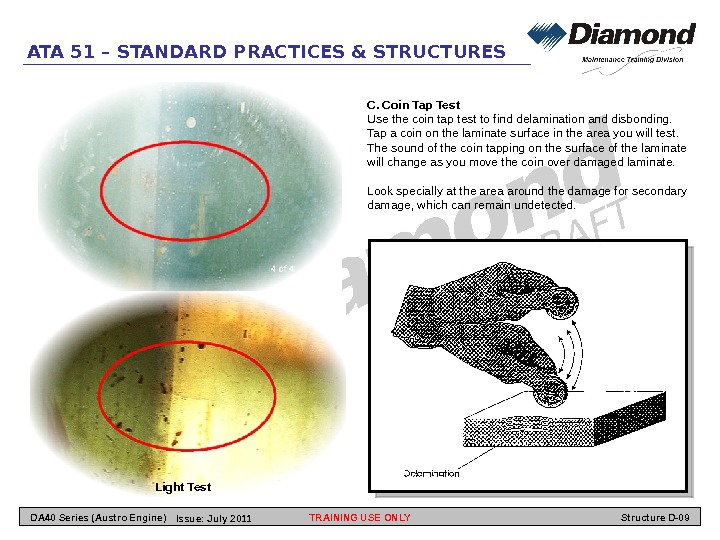
ATA 51 – STANDARD PRACTICES & STRUCTURES Light Test C. Coin Tap Test Use the coin tap test to find delamination and disbonding. Tap a coin on the laminate surface in the area you will test. The sound of the coin tapping on the surface of the laminate will change as you move the coin over damaged laminate. Look specially at the area around the damage for secondary damage, which can remain undetected. TRAINING USE ONLY Structure D-09 DA 40 Series (Austro Engine) Issue: July
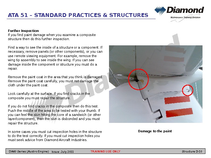
ATA 51 – STANDARD PRACTICES & STRUCTURES Further Inspection If you find paint damage when you examine a composite structure then do this further inspection. Find a way to see the inside of a structure or a component. If necessary, remove panels (or other components), or you can use remote viewing equipment. For example, remove the wing tip assembly to see inside the wing. If you can see damage inside the component or structure you must do a repair. Remove the paint coat in the area that you think is damaged. Remove the paint coat carefully, you must not damage the cloth under the paint coat. Look carefully at the surface. If you find cracks in the composite you must repair the structure. If you do not find cracks in the composite then do this test. Push the middle of the area to be tested with your thumb. If you can feel the skin hitting the core of a sandwich (or other layer/component), then the skin is disbonded and you must repair the structure. In some cases you must cut inspection holes in the structure to do the test correctly. If you must cut inspection holes you must seek advice from Diamond Aircraft Industries. Damage to the paint TRAINING USE ONLY Structure D-10 DA 40 Series (Austro Engine) Issue: July
ATA 51 – STANDARD PRACTICES & STRUCTURES Repair Processes General This Section tells you how to repair composite structures. Repairs must be carried out by approved persons. Refer to AMM chapter 51 -00 for data about the types of structures, the classification of damage, inspection techniques and for data about approved repair materials. Center of Gravity Limits When you repair an airplane, you can change the weight of the airplane. If you change the weight of an airplane, you can change the center of gravity. The further the distance of a repair from the enter of gravity, the greater the effect will be on the center of gravity. You must always weigh the airplane after a large repair and calculate the center of gravity. Refer to AMM section 08 -10 for data about weighing the airplane. Control Surface Balancing When you repair a control surface it becomes heavier. Make an estimate of the new weight of the control surface after before you do a repair. If the control surface will be too heavy then do not repair it. You must install a new item. When you repair a control surface and/or apply a new paint coat you must weigh and balance the control surface. Refer to AMM chapter 06 for data about weights and balance. AMM section 51 -60 tells you how to balance a control surface. WARNING: You must weigh and balance a control surface after repair or painting. Failure to balance a control surface may cause the airplane to fail in flight. Drain/Vent Holes You must keep all drain and vent holes in the structure of the DA 40 NG open. If you close a drain or vent hole doing a repair you must make a new hole in the same position. Holding the Component You must hold a component in the correct position when you do a repair. If you do not hold a component correctly it may move when you do the repair and cause further damage. It can also change the airplane alignment. Hold the component in a special device (jig/fixture) before you cut the repair area. If necessary, lift the airplane on jacks and level the airplane. Refer to AMM section 07 -10 for data about jacking and AMM section 08 -20 for data about leveling the airplane. Safety Precautions Most resins can cause skin disease. When you use resin/hardener use a protective barrier cream on your hands and exposed skin. You must always wear plastic gloves. WARNING: Do not get resin on your skin. Resin cause skin disease. TRAINING USE ONLY Structure D-11 DA 40 Series (Austro Engine) Issue: July
ATA 51 – STANDARD PRACTICES & STRUCTURES The resins, hardeners and solvents used for composite repairs are poisonous. You must not take food into the work area. Use a mask to protect your face and use eye-protection. WARNING: Do not get resins, hardeners or solvents in your mouth or in your eyes. These chemicals can cause disease. When you grind composites you make small particles of composite dust. These particles can irritate the skin and eyes. If you breathe these composite particles, they can cause lung disease. When you grind composite you must always use a protective cream on our hands and on all exposed skin. Wear overalls which seal at the wrists, neck and ankles. You must always wear gloves and if necessary, change them often. Use a suitable mask to protect your face and lungs. Always wear safety goggles to protect your eyes. If your skin comes into contact with composite dust, then wash it off with flowing water. Do not rub your skin while it has dust on it. WARNING: Do not get composite dust particles in your eyes, or in your mouth, or on your skin. These particles can cause disease. Workshop Conditions Keep the workshop clean and free from dust. Remove grinding dust as it occurs. The working area must not be affected by draughts. The temperature of the workshop should be maintained between 18 °C (65 °F) and 27 °C (77 °F) and must not fall below 15 °C (59 °F). The relative humidity during mixing, applying or curing or resins must not be allowed to rise above 80 %. Maintain the workshop temperature as near to 25 °C (77 °F) as possible during curing. TRAINING USE ONLY Structure D-12 DA 40 Series (Austro Engine) Issue: July
ATA 51 – STANDARD PRACTICES & STRUCTURES Maintenance Practices General These Maintenance Practices tell you about composite repair processes. Refer to Section 51 -20 for more Information about Maintenance Practices. Exterior Paint A. Paint Color Scheme CAUTION: You must paint the airplane to the Paint Color Scheme. If you do not paint the airplane to the Paint Color Scheme, you may cause damage to the airplane structure. Since full strength of the fiber composite structure has only been shown up to a temperature of 54 °C (129 °F), the outer surface of the airplane must be painted white in accordance with AMM Chapter 04. Exceptions are registration markings and warning marks, which are subject to the following restrictions : — Zone 1. No registration markings or warning markings may be applied here, except for the placards in accordance with AMM Section 11 -20. — Zone 1 a. This zone has the same restrictions as Zone 1, except that registration marks may be applied here which comply with the restrictions of Zone 2. — Zone 2. Registration markings and warning markings may be applied here. They may be any shape and color, provided that the average absorption coefficient of each area measuring 200 mm by 200 mm (8 in by 8 in) does not exceed 0. 5. Examples which meet this criterion are: Registration markings and warning markings of any shape, provided that colors with a solar absorptivity not exceeding 0. 5 (e. g. light yellow or light green) are used. Registration markings and warning markings of any color, provided that no area measuring 200 mm by 200 mm (8 in by 8 in) is covered by more than 50%. One consequence is that the width of decoration stripes must not exceed 100 mm (4 in). — Zone 3. Registration markings and warning markings of any shape and color may be applied here without restrictions. TRAINING USE ONLY Structure D-13 DA 40 Series (Austro Engine) Issue: July
ATA 51 – STANDARD PRACTICES & STRUCTURES TRAINING USE ONLY Structure D-14 DA 40 Series (Austro Engine) Issue: July
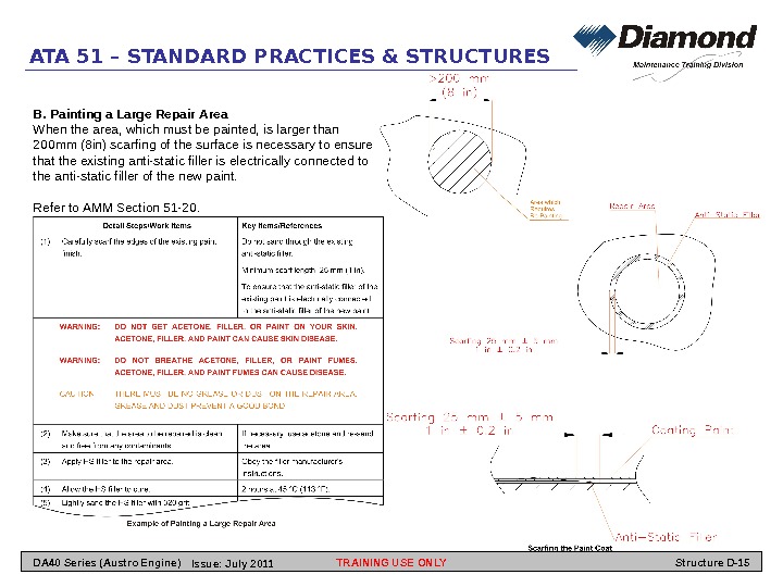
ATA 51 – STANDARD PRACTICES & STRUCTURES B. Painting a Large Repair Area When the area, which must be painted, is larger than 200 mm (8 in) scarfing of the surface is necessary to ensure that the existing anti-static filler is electrically connected to the anti-static filler of the new paint. Refer to AMM Section 51 -20. TRAINING USE ONLY Structure D-15 DA 40 Series (Austro Engine) Issue: July
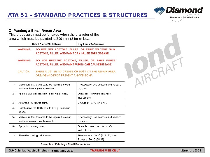
ATA 51 – STANDARD PRACTICES & STRUCTURES C. Painting a Small Repair Area This procedure must be followed when the diameter of the area which must be painted is 200 mm (8 in) or less. TRAINING USE ONLY Structure D-16 DA 40 Series (Austro Engine) Issue: July
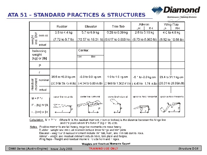
ATA 51 – STANDARD PRACTICES & STRUCTURES Control Surface Balancing General This Section tells you how to weigh and measure the residual moment of the control surfaces. WARNING: You must weigh and balance a control surface after any work which could affect its weight or its balance. Out of balance control surfaces can flutter and cause structural failure. Correct control surface balance is critical to flight safety. You must remove a control surface to weigh and balance it after: — Any repair to the control surface. — Painting the control surface. — Any report of control vibration or flutter in flight. You can use any convenient method to weigh a control surface. If you use anything to connect the control surface to the weighing device, (for example, a sling) you must weigh it separately. Then subtract its weight from the total value. For example, you use a rope sling to lift an aileron with a spring balance: — Weight of the aileron and the rope sling = 3. 8 kg — Weight of the rope sling = 0. 7 kg — Weight of the aileron = 3. 8 kg – 0. 7 kg = 3. 1 kg When you balance a control surface, the pivot angle of the control must be as shown in the Weights and Residual Moments Report. We recommend that for balancing the flaps, aileron, elevator and elevator trim tab, you put a suitable size rod through the hinge bearings. Support the rod at 2 points to keep it horizontal. To balance the rudder it must be supported at the top pivot pin and the bottom mounting bracket. The center line of the rudder must be horizontal. TRAINING USE ONLY Structure D-17 DA 40 Series (Austro Engine) Issue: July
ATA 51 – STANDARD PRACTICES & STRUCTURES TRAINING USE ONLY Structure D-18 DA 40 Series (Austro Engine) Issue: July
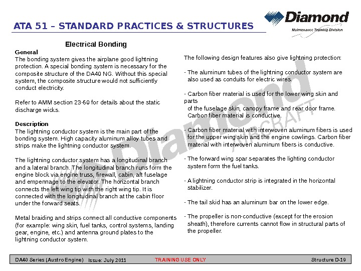
ATA 51 – STANDARD PRACTICES & STRUCTURES Electrical Bonding General The bonding system gives the airplane good lightning protection. A special bonding system is necessary for the composite structure of the DA 40 NG. Without this special system, the composite structure would not sufficiently conduct electricity. Refer to AMM section 23 -60 for details about the static discharge wicks. Description The lightning conductor system is the main part of the bonding system. High capacity aluminum alloy tubes and strips make the lightning conductor system. The lightning conductor system has a longitudinal branch and a lateral branch. The longitudinal branch runs form the engine block via engine truss, firewall, cabin, aft fuselage and empennage to the elevator. The horizontal branch connects the left wing tip with the right wing tip. It is connected with the longitudinal branch at the cabin floor under the forward seats. Metal braiding and strips connect all conductive components (for example: wing skin, fuel tanks, control systems, landing gear, engine, etc. ) and antenna ground plates to the lightning conductor system. The following design features also give lightning protection: — The aluminum tubes of the lightning conductor system are also used as conduits for electric wires. — Carbon fiber material is used for the lower wing skin and parts of the fuselage skin, canopy frame and rear door frame. Carbon fiber material is conductive. — Carbon fiber material with interwoven aluminum fibers is used for the upper wing skin and the engine cowlings. Carbon fiber material with interwoven aluminum fibers is conductive. — The forward wing spar separates the lighting conductor system form the fuel tanks. — A lightning conductor strip is integrated in the horizontal stabilizer. — The tail skid has an aluminum bar on the lower edge. — The propeller is non-conductive (except for the erosion sheath), therefore currents cannot flow in structural parts of the propeller. TRAINING USE ONLY Structure D-19 DA 40 Series (Austro Engine) Issue: July
ATA 51 – STANDARD PRACTICES & STRUCTURES TRAINING USE ONLY Structure D-20 DA 40 Series (Austro Engine) Issue: July
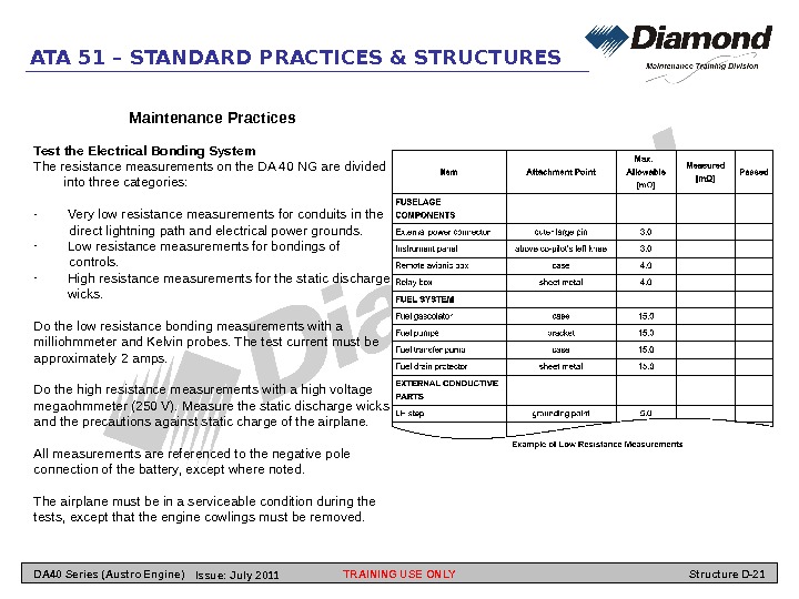
ATA 51 – STANDARD PRACTICES & STRUCTURES Maintenance Practices Test the Electrical Bonding System The resistance measurements on the DA 40 NG are divided into three categories: — Very low resistance measurements for conduits in the direct lightning path and electrical power grounds. — Low resistance measurements for bondings of controls. — High resistance measurements for the static discharge wicks. Do the low resistance bonding measurements with a milliohmmeter and Kelvin probes. The test current must be approximately 2 amps. Do the high resistance measurements with a high voltage megaohmmeter (250 V). Measure the static discharge wicks and the precautions against static charge of the airplane. All measurements are referenced to the negative pole connection of the battery, except where noted. The airplane must be in a serviceable condition during the tests, except that the engine cowlings must be removed. TRAINING USE ONLY Structure D-21 DA 40 Series (Austro Engine) Issue: July
ATA 52 – DOORS TRAINING USE ONLY Structure D-22 DA 40 Series (Austro Engine) Issue: July
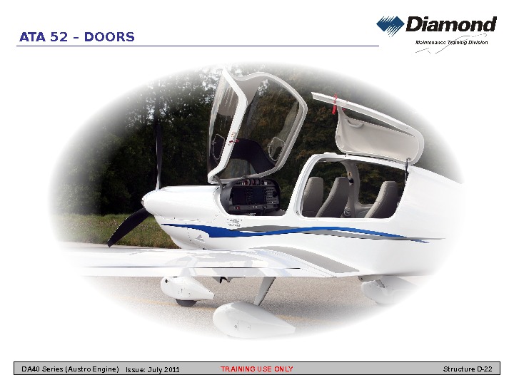
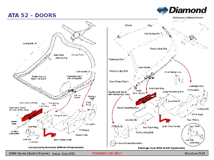
ATA 52 – DOORS the center-line. A gas strut attaches to the rear of the door and the fuselage. The gas strut holds the door open. A handle on the left of the door operates two locking bolts. The handle is red. The locking bolts are at the bottom front and rear corners of the door. The DA 40 NG has a small number of access panels. Panels which must be used often have quick-release fasteners. Other panels have the usual screws. General The DA 40 NG has two types of doors. This chapter tells you about the canopy and the passenger access door and the maintenance access panels. Description The canopy is a CFRP molding with inner and outer frames. The frames bond together. The canopy has a large one-piece acrylic glass window. The window has an emergency window on the left side. Some airplanes also have an emergency window on the right side. You can open this windows in flight. The canopy attaches to a tubular steel frame at the front. The frame attaches to two hinges on the rear face of the firewall. The canopy moves up and forward to open. A handle on the left of the canopy operates two locking bolts. The indoor and outdoor handles are red. The locking bolts are at the bottom rear corners of the canopy. The passenger door is a CFRP molding with inner and outer frames. The frames bond together. The door has a acrylic glass window. Two hinges attach the door to the top of the fuselage near TRAINING USE ONLY Structure D-23 DA 40 Series (Austro Engine) Issue: July
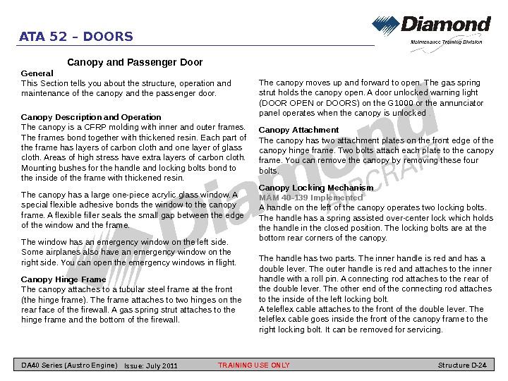
ATA 52 – DOORS The canopy moves up and forward to open. The gas spring strut holds the canopy open. A door unlocked warning light (DOOR OPEN or DOORS) on the G 1000 or the annunciator panel operates when the canopy is unlocked . Canopy Attachment The canopy has two attachment plates on the front edge of the canopy hinge frame. Two bolts attach each plate to the canopy frame. You can remove the canopy by removing these four bolts. Canopy Locking Mechanism MÄM 40 -139 Implemented A handle on the left of the canopy operates two locking bolts. The handle has a spring assisted over-center lock which holds the handle in the closed position. The locking bolts are at the bottom rear corners of the canopy. The handle has two parts. The inner handle is red and has a double lever. The outer handle is red and attaches to the inner handle with a roll pin. A connecting rod attaches to the rear of the double lever. The other end of the connecting rod attaches to the inside of the left locking bolt. A teleflex cable attaches to the front of the double lever. The teleflex cable goes inside the front of the canopy frame to the right locking bolt. It can be removed for servicing. Canopy and Passenger Door General This Section tells you about the structure, operation and maintenance of the canopy and the passenger door. Canopy Description and Operation The canopy is a CFRP molding with inner and outer frames. The frames bond together with thickened resin. Each part of the frame has layers of carbon cloth and one layer of glass cloth. Areas of high stress have extra layers of carbon cloth. Mounting bushes for the handle and locking bolts bond to the inside of the frame with thickened resin. The canopy has a large one-piece acrylic glass window. A special flexible adhesive bonds the window to the canopy frame. A flexible filler seals the small gap between the edge of the window and the frame. The window has an emergency window on the left side. Some airplanes also have an emergency window on the right side. You can open the emergency windows in flight. Canopy Hinge Frame The canopy attaches to a tubular steel frame at the front (the hinge frame). The frame attaches to two hinges on the rear face of the firewall. A gas spring strut attaches to the hinge frame and the bottom of the firewall. TRAINING USE ONLY Structure D-24 DA 40 Series (Austro Engine) Issue: July
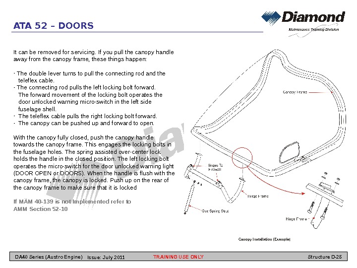
ATA 52 – DOORS It can be removed for servicing. If you pull the canopy handle away from the canopy frame, these things happen: — The double lever turns to pull the connecting rod and the teleflex cable. — The connecting rod pulls the left locking bolt forward. The forward movement of the locking bolt operates the door unlocked warning micro-switch in the left side fuselage shell. — The teleflex cable pulls the right locking bolt forward. — The canopy can be pushed up and forward to open. With the canopy fully closed, push the canopy handle towards the canopy frame. This engages the locking bolts in the fuselage holes. The spring assisted over-center lock holds the handle in the closed position. The left locking bolt operates the micro-switch for the door unlocked warning light (DOOR OPEN or DOORS). When the handle is flush with the canopy frame, the canopy is locked. Push up on the rear of the canopy frame to make sure that it is locked If MÄM 40 -139 is not Implemented refer to AMM Section 52 -10 TRAINING USE ONLY Structure D-25 DA 40 Series (Austro Engine) Issue: July
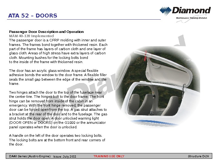
ATA 52 – DOORS Passenger Door Description and Operation MÄM 40 -139 Implemented The passenger door is a CFRP molding with inner and outer frames. The frames bond together with thickened resin. Each part of the frame has layers of carbon cloth and one layer of glass cloth. Areas of high stress have extra layers of carbon cloth. Mounting bushes for the locking bolts bond to the inside of the frame with thickened resin. The door has an acrylic glass window. A special flexible adhesive bonds the window to the door frame. A flexible filler seals the small gap between the edge of the window and the frame. Two hinges attach the door to the top of the fuselage near the center-line. The hinges bolt to the door frame. The front hinge can be removed from inside of the cabin in an emergency. With the front hinge removed, the passenger door can be forced open from the top. A gas strut attaches to a bracket at the rear of the door and to the fuselage. The gas strut holds the door open. A door unlocked warning light (DOOR OPEN or DOORS) on the G 1000 or the annunciator panel operates when the door is unlocked. A handle on the left of the door operates two locking bolts. The locking bolts are at the bottom front and rear corners of the door. TRAINING USE ONLY Structure D-26 DA 40 Series (Austro Engine) Issue: July
ATA 52 – DOORS The handle has two parts. The inner handle is red and has a double lever. The outer handle is red and attaches to the inner handle with two roll pins. A long connecting rod attaches to the rear of the double lever. The other end of the long connecting rod attaches to the inside of the rear locking bolt. A safety lock is fitted to prevent accidental movement of the handle. You must lift the safety handle before you can operate the red handle from inside the passenger compartment. To operate the red handle from the outside you must push the button next to the red handle to lift the inner safety lock. A short connecting rod attaches to the front of the double lever. The short connecting rod goes to the front locking bolt. If you pull the canopy handle away from the canopy frame, these things happen: — The double lever turns to pull the both of the connecting rods. — The long connecting rod pulls the rear locking bolt forward. — The short connecting bolt pulls the front locking bolt aft. — The aft movement of the locking bolt operates a micro switch for the door unlocked warning light (DOOR OPEN or DOORS) located on the G 1000 or the annunciator panel. The door can be pushed up and out to open. With the door fully closed, push the door handle towards the door frame. This engages the locking bolts in the fuselage holes. The forward locking bolt operates the door unlocked micro switch. When the handle is flush with the door frame, the door is locked. Push outwards on the bottom of the door frame to make sure that it is locked. If MÄM 40 -139 is not implemented refer to AMM Section 52 -10 TRAINING USE ONLY Structure D-27 DA 40 Series (Austro Engine) Issue: July
ATA 52 – DOORS TRAINING USE ONLY Structure D-28 DA 40 Series (Austro Engine) Issue: July
ATA 52 – DOORS Access Panels General The DA 40 NG has a small number of access panels. Panels which must be used often (for example the oil filler panel), have quick-release fasteners. Other panels have the usual screws. Description Most panels are GFRP moldings. Screws hold the panels in position. There are no special procedures for removing or installing access panels. TRAINING USE ONLY Structure D-29 DA 40 Series (Austro Engine) Issue: July
ATA 53 – FUSELAGE TRAINING USE ONLY Structure D-30 DA 40 Series (Austro Engine) Issue: July
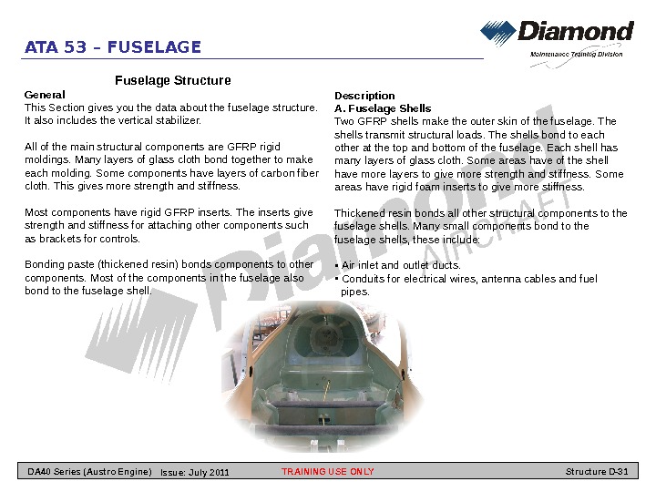
ATA 53 – FUSELAGE Fuselage Structure General This Section gives you the data about the fuselage structure. It also includes the vertical stabilizer. All of the main structural components are GFRP rigid moldings. Many layers of glass cloth bond together to make each molding. Some components have layers of carbon fiber cloth. This gives more strength and stiffness. Most components have rigid GFRP inserts. The inserts give strength and stiffness for attaching other components such as brackets for controls. Bonding paste (thickened resin) bonds components to other components. Most of the components in the fuselage also bond to the fuselage shell. Description A. Fuselage Shells Two GFRP shells make the outer skin of the fuselage. The shells transmit structural loads. The shells bond to each other at the top and bottom of the fuselage. Each shell has many layers of glass cloth. Some areas have of the shell have more layers to give more strength and stiffness. Some areas have rigid foam inserts to give more stiffness. Thickened resin bonds all other structural components to the fuselage shells. Many small components bond to the fuselage shells, these include: • Air inlet and outlet ducts. • Conduits for electrical wires, antenna cables and fuel pipes. TRAINING USE ONLY Structure D-31 DA 40 Series (Austro Engine) Issue: July
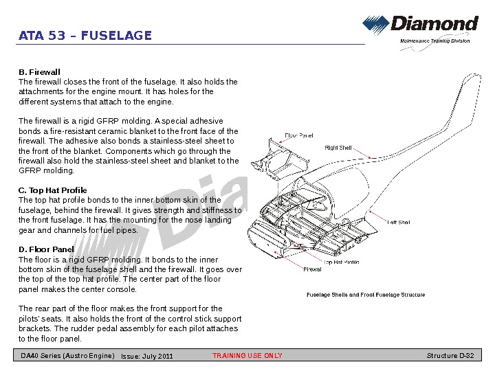
ATA 53 – FUSELAGE B. Firewall The firewall closes the front of the fuselage. It also holds the attachments for the engine mount. It has holes for the different systems that attach to the engine. The firewall is a rigid GFRP molding. A special adhesive bonds a fire-resistant ceramic blanket to the front face of the firewall. The adhesive also bonds a stainless-steel sheet to the front of the blanket. Components which go through the firewall also hold the stainless-steel sheet and blanket to the GFRP molding. C. Top Hat Profile The top hat profile bonds to the inner bottom skin of the fuselage, behind the firewall. It gives strength and stiffness to the front fuselage. It has the mounting for the nose landing gear and channels for fuel pipes. D. Floor Panel The floor is a rigid GFRP molding. It bonds to the inner bottom skin of the fuselage shell and the firewall. It goes over the top of the top hat profile. The center part of the floor panel makes the center console. The rear part of the floor makes the front support for the pilots’ seats. It also holds the front of the control stick support brackets. The rudder pedal assembly for each pilot attaches to the floor panel. TRAINING USE ONLY Structure D-32 DA 40 Series (Austro Engine) Issue: July
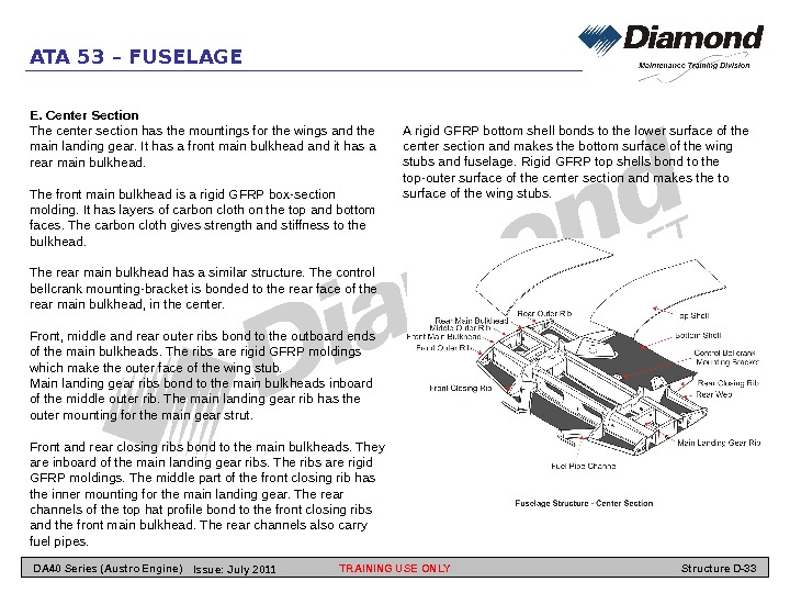
ATA 53 – FUSELAGE E. Center Section The center section has the mountings for the wings and the main landing gear. It has a front main bulkhead and it has a rear main bulkhead. The front main bulkhead is a rigid GFRP box-section molding. It has layers of carbon cloth on the top and bottom faces. The carbon cloth gives strength and stiffness to the bulkhead. The rear main bulkhead has a similar structure. The control bellcrank mounting-bracket is bonded to the rear face of the rear main bulkhead, in the center. Front, middle and rear outer ribs bond to the outboard ends of the main bulkheads. The ribs are rigid GFRP moldings which make the outer face of the wing stub. Main landing gear ribs bond to the main bulkheads inboard of the middle outer rib. The main landing gear rib has the outer mounting for the main gear strut. Front and rear closing ribs bond to the main bulkheads. They are inboard of the main landing gear ribs. The ribs are rigid GFRP moldings. The middle part of the front closing rib has the inner mounting for the main landing gear. The rear channels of the top hat profile bond to the front closing ribs and the front main bulkhead. The rear channels also carry fuel pipes. A rigid GFRP bottom shell bonds to the lower surface of the center section and makes the bottom surface of the wing stubs and fuselage. Rigid GFRP top shells bond to the top-outer surface of the center section and makes the to surface of the wing stubs. TRAINING USE ONLY Structure D-33 DA 40 Series (Austro Engine) Issue: July
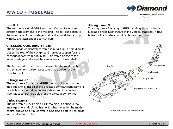
ATA 53 – FUSELAGE F. Roll Bar The roll bar is a rigid GFRP molding. Carbon tape gives strength and stiffness to the molding. The roll bar bonds to the inner face of the fuselage shell and around the canopy, window and passenger door cut-outs. G. Baggage Compartment Frame The baggage compartment frame is a rigid GFRP molding. It closes the rear of the cockpit and makes a support for the passenger seat (rear seat plan). The frame bonds to the Inner fuselage shells and the center section lower shell. The lower part of the frame has holes for the rudder cables and trim control. It also has a control rod guide for the elevator control rod. H. Ring Frame 1 The ring frame 1 is a rigid GFRP molding. It bonds to the fuselage shells just aft of the baggage compartment frame. It has holes for the rudder control cables and trim control. It also has a control rod guide for the elevator control rod. I. Ring Frame 2 The ring frame 2 is a rigid GFRP molding. It bonds to the fuselage shells aft of ring frame 1. It has holes for the rudder control cables and trim control. It also has a control rod guide for the elevator control. J. Ring Frame 3 The ring frame 3 is a rigid GFRP molding. It bonds to the fuselage shells just forward of the vertical stabilizer. It has holes for the rudder control cables and trim control. TRAINING USE ONLY Structure D-34 DA 40 Series (Austro Engine) Issue: July
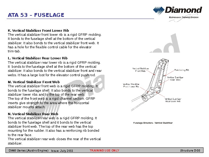
ATA 53 – FUSELAGE K. Vertical Stabilizer Front Lower Rib The vertical stabilizer front lower rib is a rigid GFRP molding. It bonds to the fuselage shell at the bottom of the vertical stabilizer. It also bonds to the vertical stabilizer front web. It has a hole for the flexible control cable for the elevator trim-tab. L. Vertical Stabilizer Rear Lower Rib The vertical stabilizer rear lower rib is a rigid GFRP molding. It bonds to the fuselage shell at the bottom of the vertical stabilizer. It also bonds to the vertical stabilizer front and rear webs. It has a large lost for the elevator control push-rod. M. Vertical Stabilizer Front Web The vertical stabilizer front web is a rigid GFRP molding. It bonds to the fuselage shell. It also bonds to the vertical stabilizer lower ribs and to the top of the rear web. The top of the front web is a rigid channel section. GFRP inserts give strength to the area where the horizontal stabilizer mounts attach. N. Vertical Stabilizer Rear Web The vertical stabilizer rear web is a rigid GFRP molding. It bonds to the fuselage shell and it bonds to the vertical stabilizer front web. The top of the rear web has the top mounting for the rudder. It also has a reinforcing rib bonded to the rear face. The vertical stabilizer rear web closes the rear of the vertical stabilizer. TRAINING USE ONLY Structure D-35 DA 40 Series (Austro Engine) Issue: July
ATA 55 – STABILIZERS TRAINING USE ONLY Structure D-36 DA 40 Series (Austro Engine) Issue: July
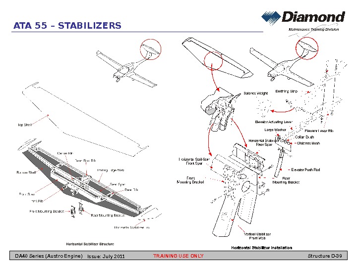
ATA 55 – STABILIZERS General The DA 40 NG has the usual stabilizers. The vertical stabilizer is part of the fuselage. The aft part of the left and right fuselage shells make the left and right shells of the vertical stabilizer. The horizontal stabilizer has top and bottom shells. Each shell has GFRP skins. The horizontal stabilizer has a front spar and a rear spar. Both spars have mounting brackets. Three pairs of ribs give strength to the center area. Two trailing edge webs hold the hinges for the elevator. The elevator has top and bottom shells. Each shell has GFRP skins with a rigid foam core. The bottom shell also makes the leading edge spar. The hinges attach to the bottom shell. A large horn with the mass balance weight attaches to the bottom shell at the center. The trailing edge carries a trim tab. The lower fin is a GFRP molding. Bolts attach the lower fin to the bottom of the fuselage. The rudder has left and right shells. Each shell has GFRP skins with a rigid foam core. The shells bond together at a flange. The hinges attach to the top face of the rudder and a flat face near the bottom of the leading edge. The horn near the top makes the rudder mass balance. TRAINING USE ONLY Structure D-37 DA 40 Series (Austro Engine) Issue: July
ATA 55 – STABILIZERS Horizontal Stabilizer General The DA 40 NG has the usual horizontal stabilizer. The horizontal stabilizer attaches to the top of the vertical stabilizer. The elevator attaches to the trailing edge of the horizontal stabilizer. Description The horizontal stabilizer has top and bottom shells. Each shell has GFRP skins. The top shell has no cut-outs. The bottom shell has a large cut-out at the rear for the elevator horn and mass balance. It also has two smaller holes forward and aft of the front spar. The horizontal stabilizer has two spars. The spars have GFRP skins with rigid GFRP inserts at the main mounting points. They also have top and bottom caps. The ends of the front spar turn back to join the aft spar at mid span. The rear spar goes almost to the tip of the horizontal stabilizer. The spars bond to the top and bottom shells with resin. Each spar has four holes for a mounting bracket. You can get access to the attachment bolts from below. The mounting brackets go down through the cut-outs in the bottom shell. Four more holes in the bottom part of each mounting bracket attach to the vertical stabilizer front web. Three pairs of ribs give strength to the center area on each side of the access holes. All are rigid GFRP moldings. They bond to the other components with resin. The rear ‘box’ ribs make a box round the large cut-out in the bottom skin. A short rear rib at mid-span gives strength to the area between the rear spar and the trailing edge web. The rear box rib has sides with bends and a top face which joins the sides. It closes the sides of the large cut-out in the bottom shell. The aft part has three holes on each side for the anchor bracket for the trim-tab mechanism. Two trailing edge webs close the trailing edges of the top and bottom shells. The outboard end of each web is a ‘J’ shape which goes round the outboard balance weight of the elevator. It extends aft at the outer side to close the elevator cut-out. The webs also holds the hinges for the elevator. The webs bond to the top and bottom shells and the rear box’ ribs with resin. A rigid GFRP fairing goes around the joint between the horizontal stabilizer and the vertical stabilizer. Four screws attach the fairing to the vertical stabilizer. TRAINING USE ONLY Structure D-38 DA 40 Series (Austro Engine) Issue: July
ATA 55 – STABILIZERS TRAINING USE ONLY Structure D-39 DA 40 Series (Austro Engine) Issue: July
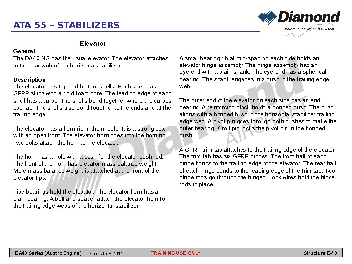
ATA 55 – STABILIZERS Elevator General The DA 40 NG has the usual elevator. The elevator attaches to the rear web of the horizontal stabilizer. Description The elevator has top and bottom shells. Each shell has GFRP skins with a rigid foam core. The leading edge of each shell has a curve. The shells bond together where the curves overlap. The shells also bond together at the ends and at the trailing edge. The elevator has a horn rib in the middle. It is a strong box with an open front. The elevator horn goes into the horn rib. Two bolts attach the horn to the elevator. The horn has a hole with a bush for the elevator push rod. The front of the horn has elevator mass balance weight. More mass balance weight is attached at the front of the elevator tips. Five bearings hold the elevator. The elevator horn has a plain bearing. A bolt and spacer attach the elevator horn to the trailing edge webs of the horizontal stabilizer. A small bearing rib at mid-span on each side holds an elevator hinge assembly. The hinge assembly has an eye-end with a plain shank. The eye-end has a spherical bearing. The shank engages in a bush in the trailing edge web. The outer end of the elevator on each side has an end bearing. A reinforcing block holds a bonded bush. The bush aligns with a bonded bush in the horizontal stabilizer trailing edge web. A pivot pin goes through both bushes to make the outer bearing. A roll pin locks the pivot pin in the bonded bush. A GFRP trim tab attaches to the trailing edge of the elevator. The trim tab has six GFRP hinges. The front half of each hinge bonds to the trailing edge of the elevator. The rear half of each hinge bonds to the leading edge of the trim tab. Two hinge rods go through the hinges. Lock wires hold the hinge rods in place. TRAINING USE ONLY Structure D-40 DA 40 Series (Austro Engine) Issue: July
ATA 55 – STABILIZERS TRAINING USE ONLY Structure D-41 DA 40 Series (Austro Engine) Issue: July
ATA 55 – STABILIZERS Lower Fin General The DA 40 NG has a removable lower fin. The lower fin is a GFRP molding. Screws attach the lower fin to the bottom of the rear fuselage. Description The lower fin is GFRP molding. It has a left shell and a right shell. The shells bond together with resin. The lower fin has a hole at the rear for a tie down rope. It also has a flat area at the bottom for a tail skid. TRAINING USE ONLY Structure D-42 DA 40 Series (Austro Engine) Issue: July
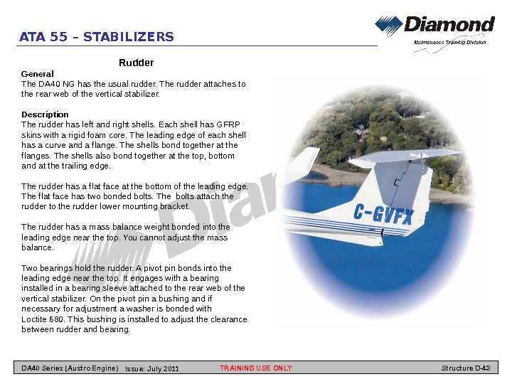
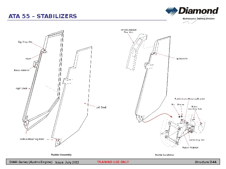
ATA 55 – STABILIZERS Rudder General The DA 40 NG has the usual rudder. The rudder attaches to the rear web of the vertical stabilizer. Description The rudder has left and right shells. Each shell has GFRP skins with a rigid foam core. The leading edge of each shell has a curve and a flange. The shells bond together at the flanges. The shells also bond together at the top, bottom and at the trailing edge. The rudder has a flat face at the bottom of the leading edge. The flat face has two bonded bolts. The bolts attach the rudder to the rudder lower mounting bracket. The rudder has a mass balance weight bonded into the leading edge near the top. You cannot adjust the mass balance. Two bearings hold the rudder. A pivot pin bonds into the leading edge near the top. It engages with a bearing installed in a bearing sleeve attached to the rear web of the vertical stabilizer. On the pivot pin a bushing and if necessary for adjustment a washer is bonded with Loctite 680. This bushing is installed to adjust the clearance between rudder and bearing. TRAINING USE ONLY Structure D-43 DA 40 Series (Austro Engine) Issue: July
ATA 55 – STABILIZERS TRAINING USE ONLY Structure D-44 DA 40 Series (Austro Engine) Issue: July
ATA 56 – WINDOWS TRAINING USE ONLY Structure D-45 DA 40 Series (Austro Engine) Issue: July
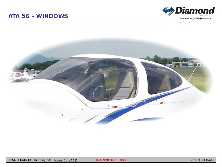
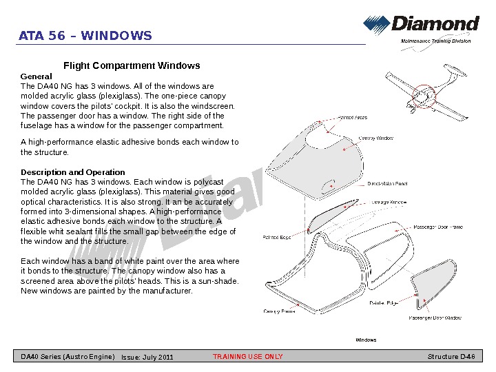
Flight Compartment Windows General The DA 40 NG has 3 windows. All of the windows are molded acrylic glass (plexiglass). The one-piece canopy window covers the pilots’ cockpit. It is also the windscreen. The passenger door has a window. The right side of the fuselage has a window for the passenger compartment. A high-performance elastic adhesive bonds each window to the structure. Description and Operation The DA 40 NG has 3 windows. Each window is polycast molded acrylic glass (plexiglass). This material gives good optical characteristics. It is also strong. It an be accurately formed into 3 -dimensional shapes. A high-performance elastic adhesive bonds each window to the structure. A flexible whit sealant fills the small gap between the edge of the window and the structure. Each window has a band of white paint over the area where it bonds to the structure. The canopy window also has a screened area above the pilots’ heads. This is a sun-shade. New windows are painted by the manufacturer. ATA 56 – WINDOWS TRAINING USE ONLY Structure D-46 DA 40 Series (Austro Engine) Issue: July
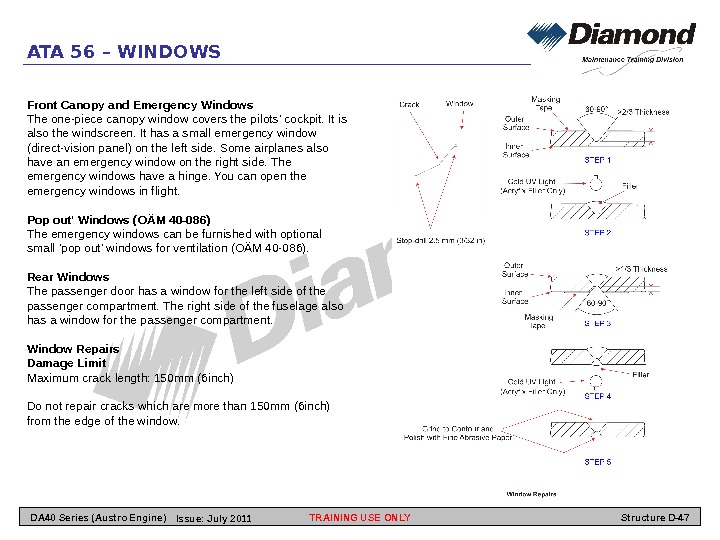
ATA 56 – WINDOWS Front Canopy and Emergency Windows The one-piece canopy window covers the pilots’ cockpit. It is also the windscreen. It has a small emergency window (direct-vision panel) on the left side. Some airplanes also have an emergency window on the right side. The emergency windows have a hinge. You can open the emergency windows in flight. Pop out’ Windows (OÄM 40 -086) The emergency windows can be furnished with optional small ‘pop out’ windows for ventilation (OÄM 40 -086). Rear Windows The passenger door has a window for the left side of the passenger compartment. The right side of the fuselage also has a window for the passenger compartment. Window Repairs Damage Limit Maximum crack length: 150 mm (6 inch) Do not repair cracks which are more than 150 mm (6 inch) from the edge of the window. TRAINING USE ONLY Structure D-47 DA 40 Series (Austro Engine) Issue: July
ATA 57 – WINGS TRAINING USE ONLY Structure D-48 DA 40 Series (Austro Engine) Issue: July
ATA 57 – WINGS Wing Structure General The DA 40 NG has cantilever wings. The wings are set low on the fuselage. Each wing has a flap attached to the inboard trailing edge. An aileron attaches to the outboard trailing edge. The wings have a monocoque structure. Each wing has top and bottom shells. The shells have CFRP outer skins, a rigid foam core and GFRP inner skins. Each wing has two I-section spars. Uni-directional carbon fiber cloth makes the spar caps. Each wing also has GFRP ribs and webs. The flaps and ailerons have a mixture of CFRP and GFRP cloth in the shells. The shells have rigid foam cores. . Description The wing has top and bottom shells. It has front and rear spars and a root rib made in three parts. Four ribs hold the fuel tanks between the spars. Flap and aileron control ribs hold the bellcranks for the control systems. A rear web closes the trailing edge of the wing. An end rib closes the outboard end of the wing. A removable GFRP tip attaches to the wing shells and outer rib with screws. Bonding paste (thickened resin) bonds the wing components to each other. TRAINING USE ONLY Structure D-49 DA 40 Series (Austro Engine) Issue: July
ATA 57 – WINGS The following section gives more data about the main parts: A. Wing Shells Each wing has top and bottom shells. Each shell has a CFRP outer skin, a rigid foam core and a GFRP inner skin. The fibers in the layers of cloth which cover the whole wing run at ± 45° to the lateral axis of the wing. The outer layer is carbon fiber. The inner layer is glass fiber. Some areas have more layers of cloth to give more strength. For example, the area around each access hole has extra layers of carbon fiber cloth. The bottom shell of each wing has seven access holes. These give access to the flap and aileron bellcranks and fuel tanks. The top shell has a hole for the fuel cap of the outer fuel tank. B. Spars Each wing has two I-section spars. The front spar on one side is the same as the rear spar on the opposite side. Many layers of uni-directional carbon fiber make the spar caps. The number of layers in the spar caps decreases from root to tip. Each spar has a shear web. The shear web has GFRP skins and a rigid foam core. Glass cloth fillets attach the spar caps to the shear web. The inboard end of each spar (the ‘stub’) goes past the root rib. The spar stub is a box-section with many layers of glass cloth wrapped round the spar caps. Two large bushes bond into the spar stub. The wing main bolts engage these bushes and attach the wing to the fuselage center section. The bushes and bolts transmit the wing bending loads into the center section. C. Root Rib Each wing has a three-piece root rib. Each piece is a GFRP molding with many layers of glass fiber cloth. The front root rib bonds to the top and bottom shells and the front face of the front spar. It has a housing for the A-bolt. The A-bolt transmits lift loads into the center section. The middle part of the root rib bonds to the top and bottom shells, the aft face of the front spar and the front face of the rear spar. It has a large oval access panel for removing the fuel tanks. The rear root rib bonds to the top and bottom shells, the aft face of the rear spar and the rear web. It has a housing for the B-bolt. The B-bolt transmits lift loads into the center section. It also has guide rollers for the flap and aileron push rods. TRAINING USE ONLY Structure D-50 DA 40 Series (Austro Engine) Issue: July
ATA 57 – WINGS D. Fuel Tank Ribs Four ribs hold the fuel tanks in each wing. Each rib is a GFRP molding with a large oval hole. The hole has a flat inner flange to hold the tank. The ribs bond to the top and bottom shells. , the aft face of the front spar and the front face of the rear spar. E. Flap and Aileron Control Ribs Each wing has two flap and one aileron control rib. The ribs are GFRP moldings. Each rib has a bend with a solid insert. The insert gives extra strength where the control bellcrank attaches. The ribs bond to the top and bottom shells, the aft face of the rear spar and the rear web. TRAINING USE ONLY Structure D-51 DA 40 Series (Austro Engine) Issue: July
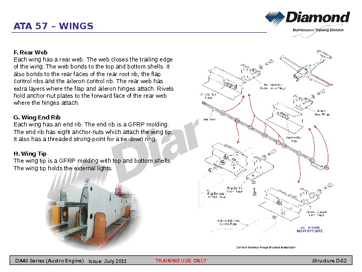
ATA 57 – WINGS F. Rear Web Each wing has a rear web. The web closes the trailing edge of the wing. The web bonds to the top and bottom shells. It also bonds to the rear faces of the rear root rib, the flap control ribs and the aileron control rib. The rear web has extra layers where the flap and aileron hinges attach. Rivets hold anchor-nut plates to the forward face of the rear web where the hinges attach. G. Wing End Rib Each wing has an end rib. The end rib is a GFRP molding. The end rib has eight anchor-nuts which attach the wing tip. It also has a threaded strong-point for a tie-down ring. H. Wing Tip The wing tip is a GFRP molding with top and bottom shells. The wing tip holds the external lights. TRAINING USE ONLY Structure D-52 DA 40 Series (Austro Engine) Issue: July
ATA 57 – WINGS Flaps General This Section tells you about the flap structure. Description A. Bottom Shell The bottom shell has inner and outer GFRP skins. It also has one layer of carbon fiber cloth in the outer skin. The skins bond to a rigid plastic foam core. The leading edge of the shell bends up to form a web. It then curves forward to form a shroud which seals the gap between flap and wing when the flap is down. The outboard end of the bottom shell also bends up to close the end of the flap. The leading edge, the ends, and the area where the horn attaches have more carbon fiber cloth to give more strength and stiffness. B. Top Shell The top shell has inner and outer GFRP skins. It also has one layer o carbon cloth in the outer skin. The skins bond to a rigid plastic foam core. The top shell bonds to the bottom shell and the inner end rib. C. Inner End Rib The inner end rib is a CFRP molding. The rib has two hole with flanged bushes. The bushes engage with the transfer pins on the transfer levers of the flap control system. The end rib bonds to the top and bottom shells. D. Flap Horn The flap horn is an aluminum alloy component. Three bolts attach the horn to the bottom surface of the flap. A small hole in the leading edge of the flap gives access to the front attaching nuts and washers. The horn also makes one of the flap hinges. Two flanged bushes in the front of the horn make the hinge. E. Flap Hinges Each flap has five hinges (as well as the flap horn). Two bolts attach each hinge to the leading edge of the flap. A small hole in the middle of the hinge gives access to the attaching nuts and washers. Each hinge has a flanged bush at the inboard end. A plastic plug seals the outboard end. TRAINING USE ONLY Structure D-53 DA 40 Series (Austro Engine) Issue: July
ATA 57 – WINGS TRAINING USE ONLY Structure D-54 DA 40 Series (Austro Engine) Issue: July
ATA 57 – WINGS Aileron General This Section tells you about the aileron structure. Description A. Bottom Shell The bottom shell has inner and outer GFRP skins. A layer of carbon fiber cloth covers a large part of the inboard area of the outer skin. The skins bond to a rigid plastic foam core. The leading edge of the shell bends up to form a web. It then curves forward to form a shroud which seals the gap between aileron and wing when the aileron moves down. The ends of the bottom shell also bend up to close the ends of the aileron. The leading edge, the ends and the area where the horn attaches have more carbon fiber cloth to give more strength and stiffness. B. Top Shell The top shell has inner and outer GFRP skins. A layer of carbon fiber cloth covers a large part of the inboard area of the outer skin. The skins bond to a rigid plastic foam core. The top shell bonds to the bottom shell. C. Aileron Horn The aileron horn is an aluminum alloy component. Three bolts attach the horn to the bottom surface of the aileron. A small hole in the leading edge of the aileron gives access to the attaching nuts and washers. The horn also makes one of the aileron hinges. D. Aileron Hinges Each aileron has three hinges (as well as the aileron horn). Two bolts attach each hinge to the leading edge of the aileron. A small hole in the middle of the hinge gives access to the attaching nuts and washers. Each hinge has a flanged bush at the inboard end. A plastic plug seals the outboard end. E. Aileron Mass Balance Each aileron has a paddle on the outboard end. To balance the mass of the aileron behind the hinge line, the leading edge of the paddle is made from heavy metal. TRAINING USE ONLY Structure D-55 DA 40 Series (Austro Engine) Issue: July
ATA 57 – WINGS LEFT BLANK TRAINING USE ONLY Structure D-56 DA 40 Series (Austro Engine) Issue: July