

b47b920cd77a78fdb50bbfe3fc8d9db3.ppt
- Количество слайдов: 38
 Ground-Mounted Verticals Dispelling Radial Misconceptions and Looking at the New 43 ft Multiband Verticals
 Ground-Mounted Verticals When I down-sized from 2+ acres back to a bungalow on a 47’ wide suburban lot, I feared that amateur radio might be in my past. There was no space for a horizontal wire antenna and there were no poles or trees to hang it from. With the neighbours so close I didn’t want a tower in the tiny yard nor a multi-band vertical on the roof. That left ground-mounted verticals. This presentation covers my investigation of radials and shows that my initial misconceptions had been keeping me from a neighbour-friendly antenna solution.
 Ground-Mounted Verticals Let’s start with some popular opinions about vertical antennas and radial systems: 1) To be effective, a ground-mounted vertical antenna must have a quarter wavelength radiator and 120 half-wave radials, over a coastal salt water marsh. 2) Vertical radiators must be a quarter wave, 5/8 wave, half wave or full wave in length. 3) Buried radials must be a 1/4 wave long on each band. 4) Radials must consist of bare wire to improve contact with the soil. 5) Radial wires must be buried at least six inches. Only some of these are partially true and only to an extent.
 Ground-Mounted Verticals The CBA 1070 k. Hz vertical antenna and its large radial field over the Tantramar salt-water marsh at Sackville, NB works superbly well. But is such an extreme setup necessary for an amateur radio installation? If not, how much does a modest vertical antenna setup suffer by comparison? For the surprising answers, let’s look at the tables and curves from the excellent June 1985 QST article by Brian Edward N 2 MF, starting with ground characteristics and proceeding through radial configurations.
 Ground-Mounted Verticals Table 1 shows various types of ground with their electrical characteristics. The Table 2 Ground types are the basis for the curves that follow. Typical amateur locations have characteristics ranging from Poor Earth to Good Earth so it is safe to interpolate between those curves to approximate expected performance.
 Ground-Mounted Verticals These curves show the effects of radial length and number over Poor Earth (sky wave component). 120 radials of. 6 wavelength produce 3. 2 d. Bi gain vs 16 radials of 0. 1 wavelength (only ~3 d. B more). That’s a half S unit at far end. Gain figures shown apply for a quarter wavelength radiator but hold for a radiator down to 1/8 wavelength.
 Ground-Mounted Verticals These curves show the effects of radial length and number over Good Earth (sky wave component). 120 radials of. 6 wavelength produce 3. 2 d. Bi gain vs 16 radials of 0. 1 wavelength (only ~2. 5 d. B better) Again figures apply for a quarter wavelength radiator but hold for a radiator down to 1/8 wavelength.
 Ground-Mounted Verticals These curves show the effects of radial length and number over Very Good Earth (sky wave component) 120 radials of. 6 wavelength produce 3. 7 d. Bi gain vs 16 radials of 0. 1 wavelength at 2. 7 d. Bi gain (only 1 d. B better) Again, gain figures apply for a quarter wavelength radiator but hold for a radiator down to 1/8 wavelength.
 angles? Horizontal wire dipoles") Ground-Mounted Verticals So what about sky wave elevation (or takeoff) angles? Horizontal wire dipoles or arrays and beams, when mounted at a height of 1/2 λ, have typical elevation angles of 30 degrees or more, (higher for lower heights). The vertical antenna may have up to a 5 to 10 degree advantage.
Ground-Mounted Verticals So what about sky wave elevation (or takeoff) angles? Horizontal wire dipoles or arrays and beams, when mounted at a height of 1/2 λ, have typical elevation angles of 30 degrees or more, (higher for lower heights). The vertical antenna may have up to a 5 to 10 degree advantage.
 Ground-Mounted Verticals What type of ground do I have in my yard? You can measure soil conductivity with a meter (See Ref 3). But what you really need to know is the average ground conductivity over several wavelengths in all directions from your antenna. This is impractical for a radio amateur to measure, especially for the lower HF bands. Actual soil conductivity may vary with moisture throughout the year (and you can’t water or salt the neighbourhood). Using Tables 1 and 2, and interpolating the curves, if necessary, is the best you can do to predict performance of an amateur radio vertical antenna.
 Ground-Mounted Verticals Buried radials are not resonant and need not be multiples of a quarter wave long. Rather they collectively form a capacitance to “real ground”. Some recommend as many and as long radials as possible, but these curves show marginal improvement. Use of insulated #12 or #14 wire minimizes corrosion. Radials can be slightly buried or on the surface, but if elevated more than a few feet, become resonant, and then should be cut for each band. The first half of this presentation has demonstrated a comprehensive analysis method for any mono-band vertical antenna with radials. Just convert the radiator and radial lengths to wavelengths and apply the curves.
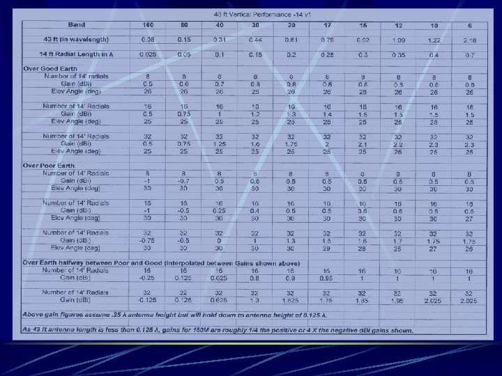
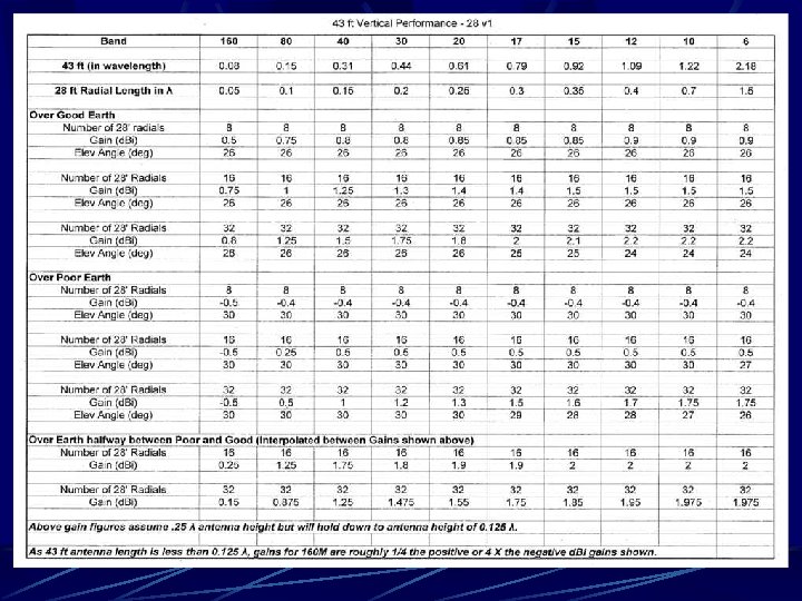
 Ground-Mounted Verticals There are many commercial multi-band vertical antennas on the market that cover HF and 6 M. Five of these are the trap-less multi-band 43 ft HF verticals (derived from the L. B. Cebic 86 ft Extended Double Zepp EDZ horizontal dipole). How do we apply the previous curves to the 43 ft verticals? This requires converting the lengths of the radiators and planned radials to wavelengths by bands.
 Ground-Mounted Verticals In his “ 43’ Antenna – Theoretical Analysis” article, Dave Cuthbert WX 7 G shows the radiation plots for the 43’ vertical on various bands Top 80 M - Green 40 M - Blue 30 M – Black Bottom 20 M - Green 15 M - Blue 10 M - Black
 Ground-Mounted Verticals He also compares the 43’ Vertical radiation plots with those of a ¼ wave monoband or trap vertical on 20, 15 and 10 M, where the longer 43’ vertical has substantial high angle radiation. His 20 M plots (R), show that the 43’ (blue) has a clear advantage over the quarter wave (black) below 25º.
 show an elevation angle") Ground-Mounted Verticals The WX 7 G 15 M plots (R) show an elevation angle of 27º for the ¼ wave vertical (blue) This compares with 37º for the 43’ vertical (black). Note: Remember in comparing the multiband 43’ vertical against a multiband trap vertical, both antenna types are compromises in order to cover multiple bands. The 43’ has no lossy traps. It also benefits from any better relative gain on receive, so it’s a good continuous coverage SWL antenna.
Ground-Mounted Verticals The WX 7 G 15 M plots (R) show an elevation angle of 27º for the ¼ wave vertical (blue) This compares with 37º for the 43’ vertical (black). Note: Remember in comparing the multiband 43’ vertical against a multiband trap vertical, both antenna types are compromises in order to cover multiple bands. The 43’ has no lossy traps. It also benefits from any better relative gain on receive, so it’s a good continuous coverage SWL antenna.
 show the substantial high") Ground-Mounted Verticals The WX 7 G 10 M plots (R) show the substantial high angle radiation one would expect from the 1. 22λ long 43’ vertical (blue). The 43’ has considerable radiation at and below the 27º lobe of the quarter wave vertical. You can optimize the 10 M and 15 M operation by shortening the 43’ vertical. Note - The WX 7 G EZNEC NEC-2 models were created with antenna base mounted 1’ over REAL GND, 16 radials, and 15 ohms of base loss resistance added. Comparison models were done with the antenna connected to MININEC GND.
Ground-Mounted Verticals The WX 7 G 10 M plots (R) show the substantial high angle radiation one would expect from the 1. 22λ long 43’ vertical (blue). The 43’ has considerable radiation at and below the 27º lobe of the quarter wave vertical. You can optimize the 10 M and 15 M operation by shortening the 43’ vertical. Note - The WX 7 G EZNEC NEC-2 models were created with antenna base mounted 1’ over REAL GND, 16 radials, and 15 ohms of base loss resistance added. Comparison models were done with the antenna connected to MININEC GND.
 EZNEC projected VSWR at the base of 43’ vertical over perfect ground from 3. 5 – 30 MHz from “The 43’ Vertical – A Theoretical Analysis” by Dave Cuthbert WX 7 G
 Ground-Mounted Verticals Several 43 ft suppliers offer their antenna with a 4: 1 unun so it may be matched through the feedline from the operating position. That match may be limited to 40 M up, unless you add an MFJ-914 Auto-Tuner Extender to the transceiver’s internal antenna tuner or use a Remote Auto-Tuner. For use with power limit linears, a 1. 5 -54 MHz 5 k. W 4: 1 unun Model 4134 S is available from Balun Designs. Matching an antenna through the feedline is not ideal due to feedline mismatch loss and also feedline radiation.
 Ground-Mounted Verticals Balun Designs Model 4134 S 5 k. W 4: 1 Unun can be used with a high power linear amplifier to “match” a 43 ft vertical from the operating position. Lower photos shows the excellent construction details. However feedline losses can be substantial.
 Ground-Mounted Verticals There are several remote auto-tuners on the market (MFJ 927, MFJ--926 B and SGC-230 etc) that mount at the antenna base. These are all in the 100 W to 200 W range. For use with linear amplifiers over 200 W, a power-limit remote auto-tuner such as the MFJ-998 RT is required. The MFJ models include built-in bias-tees to feed DC power to the remote auto-tuner over the coax feedline. Remote tuners can be fitted with a current balun (RF Isolator) e. g. MFJ-915, to keep RF off the coax shield (though a buried feedline may minimize the need for this). Canadian outside summer and winter temperature extremes may be a problem with some remote auto-tuners.
 MFJ-998 RT 1500 W (R)") Ground-Mounted Verticals MFJ Remote Tuners: MFJ-927 200 W (L) MFJ-998 RT 1500 W (R)
Ground-Mounted Verticals MFJ Remote Tuners: MFJ-927 200 W (L) MFJ-998 RT 1500 W (R)
 Decision Time Based on the curves between Poor and Good Soil, I chose to use only sixteen 14’ radials of #14 insulated wire. Thirty-two 14’ radials would improve gain by under 1 d. B at 10 M (and less on lower bands) so not worth it. Sixteen 28’ radials would improve 80 M performance by only 1 d. B (less on higher bands) so also not worth it. I chose the LDG Model S 9 v 43 antenna, a light weight forest green fiberglass telescopic“whip” lowest priced at US $199, instead of an aluminum tubing model. The ten 5’ sections (with overlap) even came in a carrying bag. The wall thickness of the S 9 v 43 is heavier than standard fiberglass tubing to stand up to wind loading.
 Results 1 The S 9 v 43 slides over a 5’ by 1. 75” ID steel conduit hammered into the ground or mounted in 6” diameter of concrete. The radiator is #14 insulated wire hung in the tubing. Photo (R) shows the radial plate. The 14’ long radials and Buryflex coax feedline were buried ½” to 1”. Not shown in the base housing are the MFJ-927 Remote Autotuner, current balun and white plastic cover (to minimize solar heating).
 Results 2 The S 9 v 43 manufacturer recommends against guying. This unguyed whip is less conspicuous than a shiny aluminum vertical and less susceptible to wind damage. Though specified for only 25 mph wind gusts, the S 9 v 43 stood up to the heavy Bluesfest gusts and the later wind remnants of Hurricane Irene. It bent way over but returned. At only 5 kg it can be taken down if strong wind in forecast. It dealt well with ice and winter temperatures below – 25 C. The MFJ-927 gave fast matches (5 sec max) for six months but stopped working at – 5 C. Though they have no published temperature specification, MFJ agreed to repair under their No Matter What warranty. On return, it tested OK after time in my freezer at – 25 C/-10 F
 Results 3 First Month Casual Contacts with S 9 v 43 on SSB 58 from Dubai on 20 M. New Country 59 from Thailand on 15 M. New Country 58 from Australia on 40 M. New Country 59 from Germany on 40 M. New Country 59 from Rochester, NY on 80 M (poorest band for 14’ radials). “Contest 59” from Edmonton in RAC CWC. Subsequent Five Months on 100% CW Almost 3000 DX CW contacts in five months (five CW contests). 137 Countries and 40 CQ Zones Worked. It’s not a beam but it is a very good utility antenna.
 Results 4 using his AIM VNA to Dave Conn VE 3 KL tested my S 9 v 43, produce multi-function tabular results in a single sweep. The following curves were created by “Z-Plots” software The SWR curve shows 100: 1 SWR at 3. 5 MHz yet the S 9 v 43 had been working on 80 M, and the MFJ-927 Auto. Tuner SWR specification is only 32: 1. How can this be?
 Results 5 MFJ’s 32: 1 SWR specification is for resistance only - 6 to 1600 Ω (1600/50 = 32) Forget SWR. To match an antenna at a given frequency, the antenna’s capacitive reactance (negative)must be offset by the tuner’s inductive reactance (positive), or the antenna’s inductive reactance must be offset by the tuner’s capacitive reactance. M 1 shows the S 9 v 43 natural resonance as 5. 5 MHz
 Results 6 2. π. F. Xc Calculating for the values shown in the previous Xs curve confirms that the MFJ-927 can match the S 9 v 43 on all frequencies within the amateur radio bands 80 M – 10 M. For 160 M, a 43. 21 µH series coil must be added. See Ref 4 For 80 M, with the MFJ-994 BRT, an 11 µH coil must be added, not because the tuner doesn’t have enough L and C but because the “L/C Limit” function limits Vpk to 1000 V. What is the value in showing the previous Rs curve?
 at 90° (¼ wave resonance) shows a") Results 7 A theoretical vertical antenna (right) at 90° (¼ wave resonance) shows a Radiation Resistance of 36 Ω The AIM 4170 tabular listing at 5. 5 MHz for Rs (Radiation Resistance + Ground Resistance) showed 43. 52 Ω. Hence Ground Resistance = 43. 52 – 36 = 7. 52 Ω Such low Ground Resistance confirms Good Earth. Efficiency = 36/43. 52 = 82% N. B. Both above calculated at 5. 500 MHz (resonance). Radiation Resistance over Perfect Ground ARRL Antenna Book 15 th Ed
Results 7 A theoretical vertical antenna (right) at 90° (¼ wave resonance) shows a Radiation Resistance of 36 Ω The AIM 4170 tabular listing at 5. 5 MHz for Rs (Radiation Resistance + Ground Resistance) showed 43. 52 Ω. Hence Ground Resistance = 43. 52 – 36 = 7. 52 Ω Such low Ground Resistance confirms Good Earth. Efficiency = 36/43. 52 = 82% N. B. Both above calculated at 5. 500 MHz (resonance). Radiation Resistance over Perfect Ground ARRL Antenna Book 15 th Ed
 Results 8 Dave Conn VE 3 KL also ran an EZNEC 2 model of my S 9 v 43 installation including the sixteen 14’ radials ½”over real ground*. The pictorial shows 28 MHz currents, where the antenna is 1. 22 λ long. * EZNEC 2 cannot deal with radials below ½”. Modeling buried radials requires EZNEC 4.
 Results 9 Above plot is S 9 v 43 SWR as modeled with EZNEC 2 by VE 3 KL with sixteen 14’ radials ½” over real ground.
 Results 10 The 7, 14 and 28 MHz elevation plots of the VE 3 KL model differ slightly from the previous WX 7 G plots due to the different ground and loss assumptions. EZNEC models show very minor losses due to thin #14 radial and radiator conductors.
 My Thanks To … Brian Edward N 2 MF for his excellent 1985 QST article Maty Weinberg, Production Coordinator of ARRL, for permission to use tables and curves from the ARRL copyright N 2 MF QST article for this presentation. Dave Cuthbert WX 7 G for permission to use his EZNEC NEC-2 VSWR curve and radiation plots. Dave Conn VE 3 KL for his many TCA antenna articles, personal discussions and the actual antenna tests and EZNEC models shown in this presentation. To Phil Salas AD 5 X for discussions on the 43 ft antenna. To Jack Belrose - VE 2 CV for his many antenna articles that maintained my interest in antennas over the years.
 References Radial Systems for Ground-Mounted Vertical Antennas – Brian Edward, N 2 MF - QST June 1985. The 43’ Vertical – a Theoretical Analysis - Dave Cuthbert WX 7 G http: //www. eham. net/articles/21272 includes 43’ VSWR curves radiation plots and discussion on Ground Loss. Measurement of Soil Electrical Parameters at HF - Rudy Severns, N 6 LF www. antennasbyn 6 lf. com. This article provides instructions on building a meter and probe(s) as well as limitations on interpretation of the results. Auto-Tuner Range Extender (or Extending the MFJ-927 to 160 -Meters) - Phil Salas AD 5 X The ARRL Antenna Book - ARRL- the antenna bible.
 Questions? Thank you de VE 3 XK
 Bury 3” or do not allow your lawn service to aerate your lawn