

fa620ec5afa6205ef461d0a17825dc6c.ppt
- Количество слайдов: 98
 Graphics Revision - 2009 Equipment – scissors, craft knives, circle cutters, safety rules, cutting boards, try square, rule, compass, stapler, eyelet punch, hole punch, drawing board, parallel motion bar, 30/60 set square, 45 set square, protractor, circle template, coloured pencils, marker pens, digital camera. Drawing techniques: Orthographic drawing – layout, dimensioning, symbol, hidden detail Sectional views Assembly drawings – draw assembled views which show location of a number of parts, include a parts list Planometric Exploded Scale Isometric and isometric circles One and two point perspective Shapes – triangles, quadrilaterals, pentagons, hexagons, octagons, ellipse Development nets – cubes, pyramids, prisms, cylinders, cones, fold lines, glue tabs, slot in tabs Enhance drawings using highlights, shading, lines, dots, reflection Show texture – concrete, metal(matt and chrome) glass, wood, plastics(textured and shiny) Thick thin line technique Printing Methods – photocopying, screen printing, letterpress, block gravure, lithography. Materials – layout paper, bleedproof paper, tracing paper, coloured paper, square grid paper, isometric grid paper, cardboard, corrugated card, foamboard, acetate, polystyrene, corriflute, self adhesive vinyl, rigid foam, balsa wood, Rigid foam – can be easily cut and shaped, PVA is suitable for joining it, water based paints can be used, some paints and adhesives will dissolve it. Smart materials Adhesives – PVA, spray, glue gun, solvent cement, epoxy resin, glue sticks, tape, double sided tape, velcro, sticky pads, fasteners, staples Surface finishes – varnish, lacquer, laminating Pre manufactured components – self adhesive labels, sticky letters/shapes, pins, paper fasteners and clips, eyelets ~ How vacuum forming is used to shape thin sheet plastic ~ How strip heater is used to shape thin plastic ~ Jigs and formers Pictograms – common signs/symbols used on packaging Be able to use tables, line graphs, pie charts, bar charts and pictograms Text – size, style, colour, justification Desk top publishing Colour wheel Paper sizes from A 5 – A 2 Quality control and quality assurance techniques Batch production – jigs, templates and stencils Pop up cards – v folds, multiple layers, parallelogram action Health and safety Ergonomics and anthropometrics Commercial production methods – job production, batch, repetitive flow, continual flow Commercial manufacturing systems – in line assembly, just in time, cell production CAD and CAM – understand what they are and how they can be used in industry and how they are used to make single items Systems have an Input, Process and Output. Types of motion – linear, reciprocating, rotary, oscillating Mechanical systems – e. g. pop up cards. How to turn motion through a right angle, reverse the direction of motion, change rotary motion into reciprocating motion, change linear motion into rotary motion. Electronic systems – flashing lights. Simple circuits and components
 Exam Dates Exam 1 – Friday 11 th June PM Exam 2 – Wednesday 23 rd June PM
 Thursday 11 th March – Circle, square, triangle, ellipse, polygon Drawing square, rectangle, circles, triangles. Drawing horizontal and vertical ellipses. Two methods for drawing octagon and hexagon. EXT - Advanced polygon worksheet to revise Candidates should be able to recognise, name and draw basic shapes. Triangles, quadrilaterals, pentagons, hexagons, octagons, ellipses.
 TASKS 1. 2. 3. Draw square 50 mm x 50 mm Draw rectangle 50 mm x 100 mm 2 methods to find the centre of a circle – diagonal lines, measuring 4. 2 methods for drawing and equilateral triangle 5. Draw circle – radius 30 mm, diameter 90 mm 6. Draw a horizontal ellipse, circle diameters 60 mm and 120 mm 7. Draw a vertical ellipse, circle diameters 80 mm and 150 mm 8. Octagons and hexagons Extension – have a go at the polygon worksheet RP
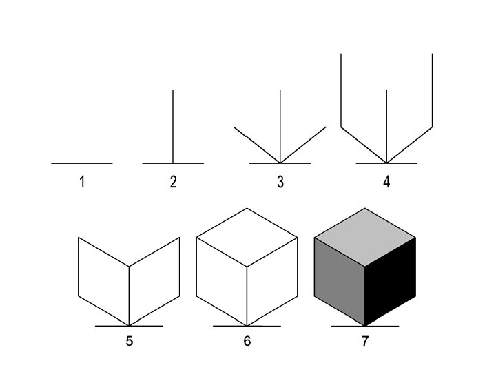
 Friday 12 th March – Isometric drawing and isometric circle Draw a square and a rectangle in isometric. Practise both methods for drawing circles in isometric – book page 49 and segment method. Isometric – 3 D drawings to show 3 faces of an object. Vertical lines stay vertical, side lines are at 30 degrees. Isometric circles are created using the segment or compass method. EXT – practice exam papers Candidates should be able to read, interpret and produce, using recommended scales, the following range of drawing systems. Both freehand instrument techniques should be used. Isometric to include isometric views of circles and the use of isometric grids
 ISOMETRIC DRAWING Side lines = 30 degrees Vertical lines stay the same Circles in isometric are drawn differently http: //www. technologystudent. com/despro_flsh/isomty 2. html
 BASIC SHAPES
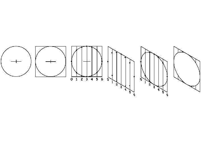
 • METHOD 2") ISOMETRIC CIRCLES • METHOD 1 – compass technique. (textbook page 49) • METHOD 2 – segment method - worksheet
ISOMETRIC CIRCLES • METHOD 1 – compass technique. (textbook page 49) • METHOD 2 – segment method - worksheet
 ISOMETRIC CYLINDERS
 ISOMETRIC GRID PAPER
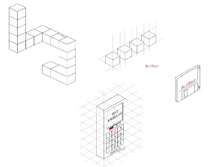
 TASKS 1. Draw an isometric cube, dimension 50 mm 2. Draw an isometric cuboid, dimensions 80 mm width, 40 mm depth and 125 mm height 3. On your isometric cube draw a circle using the compass method (textbook page 49) on the front 2 faces. 4. On the worksheet use the segment method to create an isometric circle on all the faces of the cube. Extension – have a go at using the isometric grid paper in RP
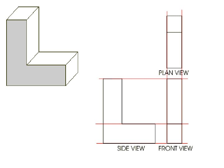
 Tuesday 16 th March – Orthographic drawing including scale and dimensioning Review scale page 59 of textbook Dimensioning on page 60 and 61. Third angle orthographic on page 62 of textbook http: //www. technologystudent. com/gprep 07/phortho 4. html example of drawing a mobile phone in orthographic. Page in revision pack on working drawings. • Orthographic – 2 D technical drawings that show usually 3 views of a 3 D object, front view, end view and plan view. Plan view is always positioned above the front view, front and end views are always viewed from ground level. End view is positioned to the right of the front view (what we see on the right we draw on the right) Show dimensions. Can show hidden detail with dashed lines. Practice drawing wooden cubes/other objects in orthographic. Add dimensions, scale, types of lines etc. EXT – practice exam papers Candidates should be able to read, interpret and produce, using recommended scales, the following range of drawing systems. Both freehand instrument techniques should be used. Orthographic third angle to include layout, dimensioning, use of symbol and hidden detail.
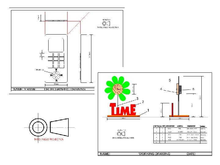
 ORTHOGRAPHIC DRAWING • Combines a number of 2 D drawings to give you details about a 3 D object • The three most common views used in this drawing technique are the plan, front and end view • Plan view is always positioned above the front view, front and end views are always viewed from ground level. End view is positioned to the right of the front view (what we see on the right we draw on the right) • The drawings of all the different views must be in line with each other. Feint construction lines are projected from one view to another to ensure they are the correct size and in the correct place • A special symbol is used to show an orthographic drawing • It may be helpful to draw an orthographic drawing on squared paper • Hidden lines are drawn as dashed lines http: //www. technologystudent. com/despro_flsh/clock 1. html
 SCALE • ENLARGEMENT SCALES 2: 1 5: 1 10: 1 20: 1 • REDUCTION SCALES 1: 2 1: 5 1: 10 1: 20 1: 50 1: 100
 DIMENSIONS • Measurements need to be added to working drawings • Measurements should always be in mm • Limit lines should be drawn out from the object and then the dimension written above this • Measurements should be read from the bottom right hand corner of the drawing • Only include the dimensions needed
 What are the two missing dimensions? Do they need to be included? 20 10 20 5 10 50
 CIRCLES R
 DIMENSIONS • There is no need to write mm on each measurement • If the measurement is less than 10 mm you draw the arrowheads differently
 TASKS • Page 57 – produce an orthographic drawing of the church with a spire, scale 2: 1, include all dimensions • Produce an orthographic drawing of one of the wooden cubes. Think about the scale of your drawing. Add all dimensions • • Scale pages 58 and 59 Dimensions pages 60 and 61 Orthographic drawing pages 62, 64 and 65 Make sure you know the symbol
 Thursday 18 th March – plastics, strip heater, vacuum former, commercial production methods and commercial manufacturing systems. Go over Power. Point presentation on plastics manufacturing and materials, students to make notes. Worksheet on commercial production methods and manufacturing techniques. Copy of Power. Point slides in revision pack and the CPM and CMT points. EXT – practice exam papers Know that thermoplastic sheet is suitable for line bending and vacuum forming. Know about polystyrene, corriflute, acetate, self adhesive vinyl Know that rigid foam can be easily cut and shaped. PVA is suitable for joining it together. Water based paints are suitable for painting rigid foam but some adhesives and paints will dissolve the foam. Know that foamboard is constructed from polystytrene foam laminated between card, these are combined to give a strong, leightweight material which can be easily cut. Candidates should be able to understand the following production methods job production, batch production, repetitive flow and continual flow process. Candidates should be able to understand the following commercial manufacturing systems cell production, in line assembly and just in time.
 • THERMOPLASTIC – this type of plastic can be heated up and shaped over and over again • THERMOSETTING PLASTIC – this type of plastic can only be heated up and shaped once. • CORRIFLUTE - like corrugated card but plastic. Strong, lightweight, good for packaging, A 3 folders • FOAMBOARD – a layer of foam in between two thin layers of card. Strong, lightweight, used for modelling, art work etc. • RIGID FOAM – used for modelling, Styrofoam. This is a light-weight dense foam. It is easy to shape with saws, files and abrasive paper and is ideal as a model making material. Can be joined using PVA glue and painted using water based paints. Some paints and glues will dissolve the material. • ACETATE – thin transparent plastic, used on overhead projectors • POLYSTYRENE – high impact polystyrene used for vacuum forming. Available in different thicknesses and colours. Variety of uses, packaging etc. • SELF ADHESIVE VINYL – thin sticky back plastic used for stickers/labels
 THE STRIP HEATER STAGE 1 – the required fold line is marked onto the plastic STAGE 2 - The plastic is placed across the rests, above the heating element The strip heater is turned on and the plastic is turned over every 30 seconds - one minute. This stops the heat rising from the element damaging the surface of the plastic. STAGE 3 - When the plastic becomes flexible it is placed in a ‘jig’. The jig is made to the correct angle, 90 degrees in this case. A square section block is then pressed against the plastic to hold it in position as it cools.
 QUESTIONS 1. Describe the stages involved in the use of the strip heater 2. Explain the safety rules that are necessary for this piece of equipment
 THE VACUUM FORMER - used to form/shape thin plastic, usually plastics such as; polythene and perspex 1. First, a former is made from a material such as a soft wood. The edges or sides are shaped at an angle so that when the plastic is formed over it, the former can be removed easily.
 The plastic sheet is removed from the vacuum former. The sheet has the shape of the former pressed into its surface. The excess plastic is trimmed so that only the plastic bowl remains - the completed item.
 QUESTIONS 1. Describe how vacuum forming is used to produce unusual shapes. 2. Name the plastics that can be used for this technique. 3. Why do the sides of the mold have to be angled and very smooth?
 • • • Commercial production methods 1. Job production – example ………………. . 2. Batch – example………………. . 3. Repetitive flow – example ……………… 4. Continual flow – example ……………… • A. This involves producing large numbers of identical products for a relatively low cost. The production is usually broken down into smaller sub sections. This method can be labour intensive or a fully automated process depending on the product being produced. B. This involves producing just one item. Every item produced is different and it is very labour intensive C. This is uninterrupted, 24 hours a day production of a basic commodity. This type of production continues because it is expensive to shut down and then re start. Only a small workforce is needed to maintain the process D. This involves the production of a specified quantity of a product. Batches can be repeated as many times as required. • • • Commercial manufacturing systems 1. In line assembly 2. Just in time • • A. A number of work stations grouped to produce a single component B. Materials and components arrive from other factories when they are needed. Finished products are dispatched immediately. This system reduces any storage of stock and allows for changes to the product to be made quickly and easily. C. This is used to mass produce many everyday items such as cars. Many of these are fully automated and require few people to mange it. • 3. Cell production
 TASKS 1. Look at examples of each plastic, discuss and make notes on the properties 2. Go through and answer questions on vacuum forming and strip heater (more information page 44 of textbook) 3. Correctly match up the commercial production methods and the commercial manufacturing systems 4. Extra information about plastics and properties pages 118 -121. Read, make notes and answer questions.
 Friday 19 th March – planometric, exploded and perspective drawing Go over key points of these 3 drawing techniques. Planometric – pages 50 and 50 Exploded – pages 52 and 53 Perspective – pages 46 and 47 Produce a page split into 6 equal boxes. Write notes in each box and draw a sketch to illustrate the key points of each drawing technique. Candidates should be able to read, interpret and produce, using recommended scales, the following range of drawing systems. Both freehand instrument techniques should be used. Planometric to include exploded views and views of circles. Perspective to include one and two point estimated perspective.
 • Planometric- good technique to show 3 dimensional view of a building or a room interior. Plan is drawn first and rotated through 90 degrees. Vertical lines are drawn to the required height. If vertical lines appear distorted reduce vertical height by 2/3. circles are constructed normally. • Exploded – shows how a product is assembled. Usually drawn as exploded isometric, perspective or planometric. Parts need to be close enough together to be able to visualise how they go together. • One point perspective – the closer an object is to us the larger it will appear to be. One vanishing point. All vertical lines stay vertical, side lines go to one vanishing point. • Two point perspective – the closer an object is to us the larger it will appear to be. Two vanishing points. All vertical lines stay vertical, sides lines go to either of the 2 vanishing points. • Isometric – 3 D drawings to show 3 faces of an object. Vertical lines stay vertical, side lines are at 30 degrees. Isometric circles are created using the segment or compass method. • Orthographic – 2 D technical drawings that show usually 3 views of a 3 D object, front view, end view and plan view. Plan view is always positioned above the front view, front and end views are always viewed from ground level. End view is positioned to the right of the front view (what we see on the right we draw on the right) Show dimensions. Can show hidden detail with dashed lines.
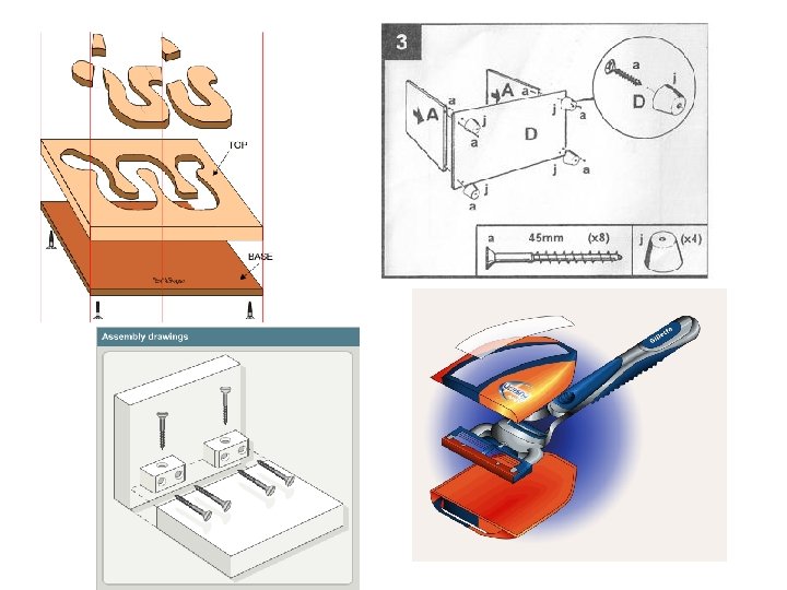
 EXPLODED or ASSEMBLY DRAWINGS • Exploded views can be drawn using any drawing technique but it is more common to use isometric • It shows how the separate parts of an object fit together • In exploded drawings it is important that the separate parts line up • You need to plan your drawing carefully leaving just the right amount of space between the parts http: //www. technologystudent. com/despro 2/pen 2. html
 Interior of a room = one point perspective • Exterior of a building = two point perspective
 TASKS 1. Split an A 3 page up into 6 boxes. Draw a cube in each box for the 6 different drawing methods. 2. Use the textbook pages to make notes on the techniques. 3. Choose and have a go at some practice exam questions based on drawing techniques.
 Tuesday 23 rd March – CAD, CAM, ergonomics and anthropometrics Show powerpoint presentation on CAD, CAM and ICT used in graphics. Students to make notes from slides. Using the textbook reference answer the specified questions. Show the powerpoint on Ergonomics and Anthropometrics. Understand how CAD and CAM are used in industrial manufacturing. Recongnise that computer systems can control machines and equipment. Understand how CAD and CAM are used to manufacture single items and small batches. Understand what ergonomics and anthropometrics are.
 CAD and CAM and ICT in Graphics
 CAD- Computer Aided Design Means using computer drawing and modelling programmes to design products instead of using paper and pencils Computer Aided Manufacture CAMMeans the process of manufacturing products with the help of computers.
 Advantages of CAD • • Saved and modified easily Quick to produce drawings both 2 D and 3 D Reduced or enlarged Common components pre drawn available High quality Accurate Linked to CAM Disadvantages of CAD • • • Expensive Detailed programs need to be learnt Risk of crashing or losing work Examples of CAD ~ Techsoft 2 D Design, Pro Desktop
 Advantages or CAM • • • Production is quicker and efficient Machines do not need to rest like people do Accurate Machines can be run continuously Quick repetition Disadvantages of CAM • • • Expensive Machine replaces peoples jobs Smaller amount of staff need to be highly trained to run machines Examples of CAM ~ Denford microrouter, Vinyl cutter
 ICT • Word processing packages – Microsoft word • Spreadsheets - excel • DTP – desktop publishing – publisher, photoshop • Graphic packages – paint, CAD – techsoft • The internet
 Graphics input devices • Barcodes – printed on packaging, read by an optical scanner • Keyboard – concept keyboard • Graphics tablet – a flat pad on which you use a special pen to draw an accurate image on the screen • Scanner – transfer images onto the computer • Digital camera – read by a computer
 Graphics output devices • Ink jet printer – cheap to buy, low quality and speed • Laser printer – more expensive therefore better quality • Plotters – accurate and good quality, used in conjunction with CAD and CAM
 TASKS • Read page 88 and 89 on CAD. Make notes and answer questions 1 and 2. • Read page 92 and 93 on CAM. Make notes and answer questions 1, 2, 3 and 4.
 Ergonomics and Anthropometrics
 Anthropometrics ‘the study of human physical dimensions’ ‘anthrops means men and metrics means measurements’ For many products complex data is required about any number of critical dimensions relating to the human form, such as height, width, length of reach.
 Ergonomics ‘the science of designing products for human use. Ergonomics uses and applies anthropometric data to ensure that products and environments are straightforward, safe and comfortable to use’ ‘concerns the interaction between the human body and products, systems or environments’
 Anthropometrics For example the design of a personal stereo would look at data concerning hand sizes.
 Data No average person If you design a product suitable for use between the 5 th and 95 th percentile then it will not be suitable for 10% of people. Anthropometric data are only specific to the populations which they describe
 Ergonomics The layout of a kitchen to make it more efficient. The interior of a car to ensure comfort to the user.
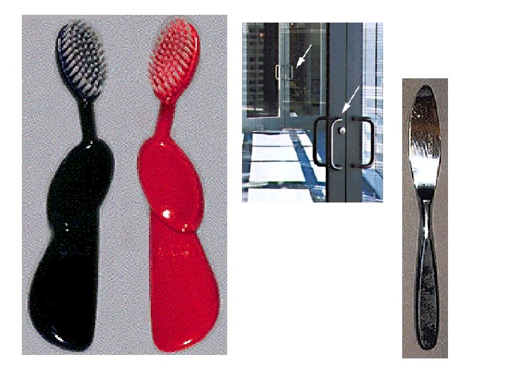
 Good aesthetics can mask bad design!
 The problem is that it is difficult to tell which control goes with which burner. The solution is to arrange the controls in the same configuration as the burners. It is quite easy to tell which burner goes with which control. Why do you think all stove tops layouts aren't designed like this one?
 TASKS 1. Read pages 16 and 17 2. Practice exam questions
 Thursday 25 th March – paper and card, sizes, texture and enhancement techniques Have a knowledge of paper sizes for A 5 -A 2. be able to identify which kind of paper is suitable for a particular situation – layout paper, cartridge paper, bleedproof paper, tracing paper, coloured paper, square grid and isometric grid paper. Understand the relationship between the thickness of the following cards and boards and appropriate construction techniques for flat card and board, corrugated board. In pairs try matching up the name of the material with the description. Go over answers on Power. Point slide. Paper sizes page 116. using a piece of A 3 paper mark out the sizes for A 4, and A 5. record the sizes for A 3 and A 2. Candidates should be able to suggest form and material using the following range of enhancement techniques. Tone – apply an understanding of light, shade and shadow to enhance form and mass in pictorial drawing. To include the use of highlights, shading, lines, dots, reflections. Thick and thin line technique – to enhance pictorial drawings to create impact to make objects appear more solid. Texture – use textural illustration to illustrate wood, plastics matt and shiny, glass, metal matt and chrome and concrete. Read pages 74 – 77 and make appropriate notes. Try out the techniques.
 Tracing Paper Transparent, hard and strong. Its translucency makes it suitable for tracing fine details drawn with fine lines. Used for working drawings. Corrugate d Card Two or more layers of card with a fluted inner section to add strength with very little increase in weight. Used for packaging objects which need protection during transportation. Isometric Paper A ready printed sheet with lines already set at 30º, 60º and 90º lines. Used for isometric projections. Grid Paper A ready printed sheet with lines vertically and hotizontally to help draw working drawings. The grids are measued in millimetres. Used for orthographic projections. Cardboard This is a cheap, recyclable stiff board with a good surface to print onto. Used for packaging, boxes and cartons. Ink Jet Card This type of card is treated so that it can be passed through ink jet printers. Used to achieve high quality print finishes. Sugar Paper Coloured paper which has contrasting colours for use in tonal drawings. Different weights and textures available for different activities. Used for display work, fades in sunlight. Layout Paper A thin, fairly transpaprent white paper which provides a cheap medium for designers to use for visualising a project or design. Used in preparation of final ideas. Cartridge / Photocopy Paper Good quality surface for pencils, pens and markers. The soft surface can also be used for crayons, pastels, inks and watercolours. Used for design drawings, sketching.
 foam board a layer of lightweight thin foam that is sandwhiched between two layers of card. It is an excellent modelling material as it is strong, lightweight, has a smooth surface finish and can be cut easily with a knife, balsa wood comes in either sheet or block form. It is lightweight and soft so can be cut easily with a sharp knife. It is suitable for making mock ups and prototypes. styrofoam a suitable material for 3 D modelling. It can be cut, shaped, formed, painted and sections glued together polystrene sheet ideal for vacuum forming and line bending. Sheets available in wide variety of colours and thicknesses. It is strong and lightweight corriflute corrugated flutes are sandwhiched between two thin sheets of plastic. It is lightweight, strong and available in a variety of colours. It is easy to cut and is an ideal modelling material. Bleed Proof Paper Has similar qualities to cartridge paper but specifically good at isolating water based paints and pens so they don't run into areas where you don't want them. Used in high quality presentations White Boar d This is a strng medium whose surface has been bleached to provide an excellent surface for printing. Used for good quality packaging and book covers Duplex Boar d This provides a less expensive alternative to white board and also a different texture for printing. Used mainly in food packaging since recycled material acnnot be used for this purpose.
 PAPER SIZES A 2 = 420 mm x 594 mm A 3 = 297 mm x 420 mm A 4 = 210 mm x 297 mm A 5 = 148 mm x 210 mm Standard photocopying paper is 80 gsm (grams per square metre)
 Cardboard = thicker material (to") Card and Cardboard Card = thinner material (greetings cards) Cardboard = thicker material (to mount prints) Thickness is usually measured in microns (1000 microns = 1 mm) Card 200 – 1000 microns Cardboard is over 1000 microns
Card and Cardboard Card = thinner material (greetings cards) Cardboard = thicker material (to mount prints) Thickness is usually measured in microns (1000 microns = 1 mm) Card 200 – 1000 microns Cardboard is over 1000 microns
 Thick and thin line technique Imagine there is a spider on one of the surfaces of the 3 D object. If he crawls onto another surface and you can still see him then that line should be thin. If he crawls onto the next surface and you can’t see him then that line should be thick. All external lines = THICK Used for an edge where only one surface can be seen Most internal lines (but not always) = THIN Used for an edge where both surfaces can be seen
 By applying different TONES to a drawing you can make the object look more three dimensional Using SHADING, LINES AND DOTS the closer you draw the lines or dots together of the harder you pres the darker the TONE is
 Curved surfaces, the amount of light reflected gets less as the surface turns away from the light source and therefore the tone you use needs to be darker. A HIGHLIGHT should be used, a white area, that is closest to the light source You can use SHADOWS on drawings to increase the feeling of depth and to suggest the object is resting on a surface. A shadow will be an elongated shape of the object, it will be on the side furthest away from the light source and will be darker than the darkest tone on the object.
 TONE = the various shades that can be produced from one different colour SHADING = a technique used to show light falls on an object HIGHLIGHT = a bright area where light is reflected from the edge or surface of an object SHADOW = a dark area formed when an object is in the way of rays of light
 WOOD – drawing curved lines on the end to represent growth rings and straight lines on the sides to represent the grain. Use a combination of brown, yellow and orange MATT METAL - a series of straight lines can create a hard effect, altering the distance between the lines gives lighter and darker tones.
 CHROME METAL – reflections appear as high contrast areas of dark and light TEXTURED PLASTIC – represented by drawing small, irregular shapes over the required area. CONCRETE – represented by a series of dots and small irregular shapes
 SHINY PLASTIC – draw a number of short parallel lines across the surface or shade the surface evenly and rub out wavy lines GLASS AND CLEAR PLASTIC – shade the suface using a light blue pencil and then rub out areas to suggest reflections. Feint broken lines can be used to show details that can be seen through the glass or plastic.
 RENDERING
 TASKS 1. In pairs try matching up the name of the material with the description. Go over answers on Power. Point slide. 2. Paper sizes page 116. using a piece of A 3 paper mark out the sizes for A 4, and A 5. record the sizes for A 3 and A 2. 3. Read pages 74 – 77. Have a go at some of the enhancement techniques on the worksheet provided.
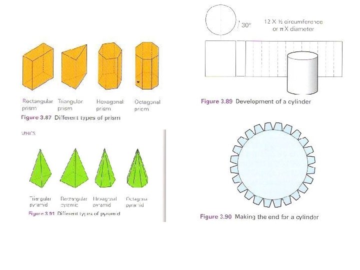
 Friday 26 th March – Development nets – cubes, prism, cylinders, pyramids and cones. To include correct representation for fold lines, glue tabs and slot in tabs. Go through Power. Point slides, make appropriate notes on your hand out. Pages 80 – 83 – make appropriate notes Practice exam questions
 Cut lines Fold lines Glue tabs Different nets to produce a cube
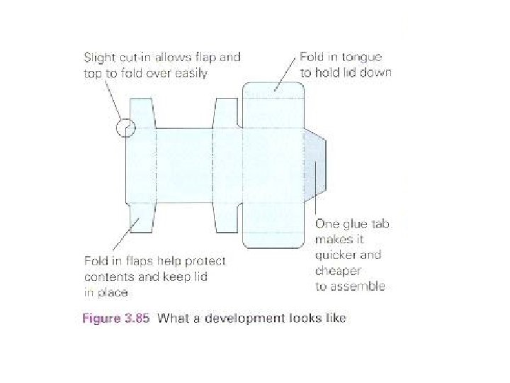
 Slot and tab fixings allow part or all of a product to be assembled and disassembled without causing damage to the product. Products joined together with slot and tab fixings – can be sent flat packed, less costly for manufacturer to produce, no assembly costs, easier and cheaper to transport and store because they take up less space and are less likely to be damaged.
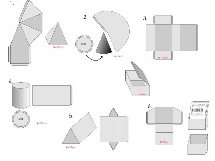
 TASKS 1. 2. 3. 4. Read pages 80 – 83 Answer question 1 on page 83 Look at information in RP about nets Have a go at drawing the net for one of these pieces of packaging 5. Find exam questions to practice about development nets
 Tuesday 30 th March – exam theme SAFETY SIGNS AND BARRICADE TAPES • Materials and production methods • Joining and fixing methods of floor signs • Stability of floor signs • Mandatory symbols and colours of safety signs • Environmental implications such as biodegradable materials • Packaging of barricade tapes
 Thursday 1 st April – printing methods and smart materials Show examples and information on Power. Point about printing methods and smart materials. Students to make notes. Understand the basic principles of commercial printing. Letterpress, block gravure, lithography. Know that some smart materials respond to changes in temperature, light or applied voltage.
 Printing Processes • Cost • Quality • Quantity
 The black strips seen in the animation opposite represent individual letters arranged in a line, forming a sentence. Ink is first applied to the letters with a roller and the paper is then placed between the top and bottom parts of the press. The top part of the press is then pushed down onto the paper and the ink is transferred from the letters. When the paper is removed the printing can clearly be seen. This process can be repeated continually producing large numbers of printed papers. LETTERPRESS
 In simple terms the letter or shape to be printed stands above the surface. Ink or paint is then rolled across the shape/letter and paper is then pressed down onto it. When the paper is lifted up the ink/paint has been transferred to the paper. This process can be repeated any number of times. BLOCK PRINTING
 • Letterpress ~ expensive as individual letters have to be made, high quality paper is used. Used for short runs of high quality stationery. • Blockprinting
 • Gravure ~ high quality prints in large volumes, expensive. Used for high quality reproduction of photos, paintings and full colour magazines. • Images are etched onto a plate through a screen, image is broken into dots. Ink fills the dots. Rubber covered cylinders press the paper into the dots creating a printed image.
 Gravure
 Screen Printing 1. The material to be printed on is placed on top of the base. In the example, paper is being used. 2. A template made from card with the required shape cut of it is placed on top of the paper. 3. A screen is placed on top of the template. The screen is made of stretched nylon fabric and has a wood frame to hold it in place. 4. Ink is then squeezed onto the nylon fabric. 5. A blade is used to spread the ink out and push it through the fabric, through the template, and onto the paper. 6. The paper is taken out of the screen printing equipment and the printed pattern can clearly be seen. Used to print designs onto T-shirts, banners, signs, shopping bags, posters and packaging. Simple stencils can be made to produce relatively cheap prints fast. More sophisticated commercial screen printing can produce thousands of copies per hour at a good quality.
 • Lithography • The process has a printing plate, with the image in relief which is free to rotate. Ink is applied to the printing plate which is dampened. This repels ink of any non image areas. The printing plate then transfers an inked image onto the rubber blanket cylinder which in turn presses the image onto the paper as it is fed through. • Areas to be printed on attract the ink (grease) and areas not to be printed on attract water.
 Lithography
 • High speed and cheap, most common used method. • Print in full colour. 4 colour process called CYMK process (yellow, cyan, magenta, black. )
 Dry Printing • Photocopiers • Laser Printers
 Smart Materials Definition – they sense conditions in their environment and respond to these conditions. They appear to think and have a memory as they will revert back to their original state time and time again. Know that some smart materials respond to changes in temperature, light or applied voltage.
 Thermochromic colours • Change colour in response to a temperature change. Colour disappears above 27 degress and reappears below that.
 • Photochromic inks – colours change in response to a change in the level of light (t shirt) see example Smart wire – changes length or shape in response to a temperature change
 There are many out there… • • Liquid crystal displays Polymorph Electroluminescent panels Smart grease Thermochromic inks Photochromic inks Smart wire
 TASKS 1. Make notes about printing methods, see information in revision packs 2. Make notes and see demonstrations about smart materials. 3. Use the internet to do further research about other smart materials and to find out more information about commercial printing methods.