95fe4d9d8539dafacdace470ffdb265d.ppt
- Количество слайдов: 165
 GAS / FLAME DETECTION GAS / DUST MONITORING YOUR ENVIRONMENT, YOUR SAFETY, LET ’S MASTER THEM TOGETHER
 Gas Detection Objectives • Measure gas before hazardous concentration is present • Provide outputs for Emergency Action • Suitable for extreme environments (arctic, tropic, etc. . . ) • Complement to Flame Detection equipment • Cost-effective protection
 • The poisoning (Tox) • The suffocation") The risks incurred: • The explosion (EX) • The poisoning (Tox) • The suffocation (O 2)
The risks incurred: • The explosion (EX) • The poisoning (Tox) • The suffocation (O 2)
 EXPLOSION RISKS
 3 parameters for an EXPLOSION • Requirement for an explosion: the ignition triangle Always present in the air
 IGNITION TEMPERATURE. . . • It is the temperature from which a product starts spontaneously its combustion without the intervention of an outside source (spark). • H 2 : 560°C • CH 4 : 550°C • acetone : 465°C • ethyl ether : 160°C • carbon sulphide : 102°C
 • It is the minimal temperature from which a mixing of vapours,") FLASH POINT…(FLP) • It is the minimal temperature from which a mixing of vapours, issued from liquids and air, may inflame in normal conditions of pressure. • Ethyl ether : - 45°C • essence (oi 100) : - 37°C • acetone : - 17°C • gas oil : + 55°C
FLASH POINT…(FLP) • It is the minimal temperature from which a mixing of vapours, issued from liquids and air, may inflame in normal conditions of pressure. • Ethyl ether : - 45°C • essence (oi 100) : - 37°C • acetone : - 17°C • gas oil : + 55°C
 About explosive atmosphere. . . • For each combustible gas or vapour in usual conditions of given temperature and pressure, there are: • a LOW EXPLOSIVE LIMIT : LEL • an UPPER EXPLOSIVE LIMIT : UEL
 Combustible gases • LEL : lower explosive limit • The minimum concentration of gas or vapor mixed with air that will cause an explosion when its comes in contact with an ignition source.
 Combustible gases • UEL : upper explosive limit • The maximum concentration of gas or vapor mixed with air that will cause an explosion when it comes in contact with a ignition source.
 AIR/GAS CONCENTRATIONS 100% air LEL 5% volume Alarm at 20% of LEL lean 0% explosive 100% of LEL UEL 14. 7% volume (catharometre: % gas) rich
 a NEW directive for EUROPE ! Potentially EXplosive ATmospheres
 = European instruments using • 1999/92/CE (") ATEX DIRECTIVES • 94/9/CE ( manufacturers’ directive) = European instruments using • 1999/92/CE ( workers’ directive) = employees protection: • annexe I: types of zones • annexe II: categories of instruments for each zone.
ATEX DIRECTIVES • 94/9/CE ( manufacturers’ directive) = European instruments using • 1999/92/CE ( workers’ directive) = employees protection: • annexe I: types of zones • annexe II: categories of instruments for each zone.
 NEW DIRECTIVES ATEX. . . • Since July 2003, it has been mandatory that all equipment with a potential source of ignition which is being sold on the european market for the first time is accompagnied by a declaration of conformity to the ATEX product Directive 94/9/EC. • Since july 2003, it has been mandatory that all new installations (and modifications to existing installations) should meet the requirements of the ATEX User directive 1999/92/EC.
 NEW DIRECTIVES ATEX. . . • By July 2006, all plants within Europe should be able to demonstrate full compliance with the requirements of 1999/92/EC as adopted in each member state. • In the UK this is « the dangerous substances and explosive atmospheres regulations » : DSEAR.
 ww w. Or : w new ap ww pr. in oa ch er is. . or fr g NEW DIRECTIVE ATEX. . . Or: europa. eu. int/comm/enterprise/atex/index. htm
 • Requires in short: • a certification delivered by") The new directive ATEX (01/07/2003) • Requires in short: • a certification delivered by a notified laboratory • CE marking to be affixed to all electrical and electronic instruments marketed in EUROPEAN UNION MEMBER STATES(The CE marking guarantees that the instrument conforms to applicable electromagnetic radiation and immunity requirements). • Compliance is mandatory, which means you must ensure that your products meet all of the directive’s requirements.
The new directive ATEX (01/07/2003) • Requires in short: • a certification delivered by a notified laboratory • CE marking to be affixed to all electrical and electronic instruments marketed in EUROPEAN UNION MEMBER STATES(The CE marking guarantees that the instrument conforms to applicable electromagnetic radiation and immunity requirements). • Compliance is mandatory, which means you must ensure that your products meet all of the directive’s requirements.
 List of European Standard relevant to Performance Requirements ( additional standard to Explosion Protection i, d, e , m, etc ) and mandatory for safety relevant devices according article 1. 5 de l’Annex II de la Directive Atex 94/9/CE EN 61779 -1 ( replace EN 50054 ). Performance requirements of Electrical apparatus for the detection and measurement of flammable gases - Part 1: General requirements and test methods
 : Performance") List of European Standard EN 61779 -2 ( replace EN 50055 ) : Performance requirements for group I apparatus indicating a volume fraction up to 5 % methane in air . - EN 61779 -3 ( replace EN 50056) : Performance requirements for group I apparatus indicating a volume fraction up to 100 % methane in air . EN 61779 -4 ( replace EN 50057) : Performance requirements for group II apparatus indicating a volume fraction up to 100% lower explosive limit. . - EN 61779 -5 ( replace EN 50058) : Performance requirements for group II apparatus indicating a volume fraction up to 100% volume. .
List of European Standard EN 61779 -2 ( replace EN 50055 ) : Performance requirements for group I apparatus indicating a volume fraction up to 5 % methane in air . - EN 61779 -3 ( replace EN 50056) : Performance requirements for group I apparatus indicating a volume fraction up to 100 % methane in air . EN 61779 -4 ( replace EN 50057) : Performance requirements for group II apparatus indicating a volume fraction up to 100% lower explosive limit. . - EN 61779 -5 ( replace EN 50058) : Performance requirements for group II apparatus indicating a volume fraction up to 100% volume. .
 List of European Standard EN 50104: Electrical apparatus for the detection and measurement of oxygen – Performance requirements and test methods. EN 50270: Electromagnetic compatibility - Electrical apparatus for the detection and measurement of combustible gases, toxic gases or oxygen EN 50271: Electrical apparatus for the detection and measurement of combustible gases, toxic gases or oxygen - Requirements and tests for apparatus using software and/or digital technologies.
 List of European Standard relevant to Performance Requirements not mandatory, eg not yet in the Atex list for harmonised standard EN 45544 -1 : Workplace atmospheres - Electrical apparatus used for the direct detection and direct concentration measurement of toxic gases and vapours -- Part 1: General requirements and test methods EN 45544 -2 : Workplace atmospheres - Electrical apparatus used for the direct detection and direct concentration measurement of toxic gases and vapours -- Part 2: Performance requirements for apparatus used for measuring concentrations in the region of limit
 List of European Standard relevant to Performance Requirements not mandatory, eg not yet in the Atex list for harmonised standard EN 45544 -3 : Workplace atmospheres - Electrical apparatus used for the direct detection and direct concentration measurement of toxic gases and vapours -- Part 3: Performance requirements for apparatus used for measuring concentrations well above limit values EN 45544 -4 : Workplace atmospheres - Electrical apparatus used for the direct detection and direct concentration measurement of toxic gases and vapours -- Part 4: Guide for selection, installation, use and maintenance
: continued. . . • Safety systems fail safe application.") The new directive ATEX (01/07/2003): continued. . . • Safety systems fail safe application. • GAS or DUST hazardous areas indication (marking) • production quality assurance • product verification • conformity to type tests carried out under the responsability of notified organisme.
The new directive ATEX (01/07/2003): continued. . . • Safety systems fail safe application. • GAS or DUST hazardous areas indication (marking) • production quality assurance • product verification • conformity to type tests carried out under the responsability of notified organisme.
 ATEX / CENELEC: marking • Until July 2003, a new marking: PROTECTION MODE GAS GROUP CENELEC INSTRUMENT Group europ Directives. organism explo category gas T° Class cenelec protection Class gas T° Class
 CE MARKING example • The certified equipment must carry a plate indicating : -the name and address of the manufacturer -designation of the type of equipment -CE marking followed by the identification number of the organism where such body is involved in the production control stage: CE xxxx -the serial number of the equipment - year of construction -specific marking followed by group II for group II, 2 for category 2 and G for gas - complementary marking: EEx d IIB T 4 INERIS xx. ATEXxxxx X
 What is an HAZARDOUS AREA as per ATEX 1999/92/CE: annexe I ?
 ATEX 1999/92/CE • New directive ATEX concerning the instruments in hazardous areas and mines “group I”: • the whole concentrations: M 1 • above a limit value: M 2
 ATEX 1999/92/CE: ZONES • New directive ATEX concerning the instruments in hazardous areas and surface industries “group II” distinguishes the next groups of zones: • Zone 0 G (gas) and zone 20 D (dusts) • Zone 1 G (gas) and zone 21 D (dusts) • Zone 2 G (gas) and zone 22 D (dusts)
 ZONE 0 G /20 D ATEX probability = very high • Where ignitable concentrations of flammable gases, vapours, liquids or dusts can exist all of the time or some of the time and for a long time under normal operating conditions. required equipment (annexe II): category 1= ia only ! intrinsic Safety
 ZONE 1 G/21 D ATEX probability = high • Where ignitable concentrations of flammable gases, vapours, liquids or dusts can exist some of the time under normal operating conditions. • required equipment (annexe II): category 2 = d or is or e.
 ZONE 2 G/22 D ATEX probability = low • Where ignitable concentrations of flammable gases, vapours, liquids or dusts are not likely to exist under normal operating conditions. • Required equipment (annexe II): category 3 (minimum protection).
 DANGEROUS ZONE: example • In accordance with the new regulation Required equipment ATEX: CATEGORY 3 CATEGORY 2 CATEGORY 1
 GAS and EQUIPMENT CLASSIFICATION.
 drew") Explosion groups • The IEC and the CENELEC (European committee of electrotechnics normalisation) drew up a classification of flammable products : • the I group only concerns the equipment used in firedamp mines. • the IIB group includes all gases except hydrogen, acetylene, carbon sulphide and nitrile of ethyl • the IIC group includes all gases and vapours.
Explosion groups • The IEC and the CENELEC (European committee of electrotechnics normalisation) drew up a classification of flammable products : • the I group only concerns the equipment used in firedamp mines. • the IIB group includes all gases except hydrogen, acetylene, carbon sulphide and nitrile of ethyl • the IIC group includes all gases and vapours.
 classification of temperatures • "T" followed by the number from 1 to 6 indicates the class of the maximum temperature of surface that can bear the device, taking care of a security’s coefficient : no surface of the equipment in contact with the gas/air mixture should exceed the MIT of the gas. • Each flammable gas or vapour has a specific Minimum Ignition Temperature. • This classification is relevant to a given surrounding temperature ( 40°C).
 classification of temperatures • Example: T 6 Gas detectorcasing Internal fault 85°C max Gas detected ignition T° >85°C
 Temperature classes • To ease the selection of equipment, six different temperature classes have been created for both gases and equipment. IEC CENELEC T 6 T 5 T 4 T 3 T 2 T 1 (group II) maximum temperature 85°C 100°C 135°C 200°C 300°C 450°C of surface
 Function of Explosion protection • The function of the discipline of explosion prevention is to ensure that there is a negligible probability that a means of ignition and any significant quantity of a potentially explosive atmosphere can occur in the same location at the same time. • Both mechanical and electrical methods are imployed and have been classified under 4 categories:
 (EN 50021) • Flameproof") 4 categories of protection • Non-incendive equipment (comparable with n) (EN 50021) • Flameproof or explosion-proof equipment (d) (EN 50018) • intrinsic safety equipment (i) (EN 50020) • increased safety equipment(e)(EN 50019)
4 categories of protection • Non-incendive equipment (comparable with n) (EN 50021) • Flameproof or explosion-proof equipment (d) (EN 50018) • intrinsic safety equipment (i) (EN 50020) • increased safety equipment(e)(EN 50019)
 • Transmitters « n » for zones 2 (gas) and 22(dusts) •") NON-INCENDIVE EQUIPMENT(n) • Transmitters « n » for zones 2 (gas) and 22(dusts) • In accordance with regulation CEI 79 -15: minimum protection (non sparking) • Typical applications: instrumentation, control gear, electronic systems, measurement and control.
NON-INCENDIVE EQUIPMENT(n) • Transmitters « n » for zones 2 (gas) and 22(dusts) • In accordance with regulation CEI 79 -15: minimum protection (non sparking) • Typical applications: instrumentation, control gear, electronic systems, measurement and control.
= containment • Elements sensitive to produce a spark are") FLAMEPROOF or explosion-proof equipment (d)= containment • Elements sensitive to produce a spark are enclosed in casings resistant to an eventual internal explosion. • This material is in accordance with the decree of March 28, 1960:
FLAMEPROOF or explosion-proof equipment (d)= containment • Elements sensitive to produce a spark are enclosed in casings resistant to an eventual internal explosion. • This material is in accordance with the decree of March 28, 1960:
 FLAME PROOF TRANSMITTERS: spécifications of installation • Transmitters « d » for zones 1 and 2(gas) and 21 and 22(dusts) • The cable will be mecanicly protected • Transmitter ’s body will be connected to the earth • If connections are in classified area: made in certified housing. • Typical applications: switch gear, motors , pumps.
 = prevention of ignition • Intrinsic safety aims to") equipment with intrinsic safety (i) = prevention of ignition • Intrinsic safety aims to limit the level of energy release under any circumstances ( MIE !…. . ) • It is the ideal equipment in particular in an atmosphere with hydrogen.
equipment with intrinsic safety (i) = prevention of ignition • Intrinsic safety aims to limit the level of energy release under any circumstances ( MIE !…. . ) • It is the ideal equipment in particular in an atmosphere with hydrogen.
 INTRINSIC SAFETY: FAULT CONDITIONS • The definition of intrinsic safety includes reference to fault conditions. • Two categories of intrinsically safe instrument are defined in the standards: ia and ib. • The categories differ in two principal respects: - the number of specified faults which the instrument can sustain without producing a risk of ignition - the values of the safety factor which are applied to the ignition data used in the design. . .
 INTRINSIC SAFETY: FAULT CONDITIONS • Category « ia » : • instruments of this category must be incapable of causing ignition in normal operation or with a single fault or with any two independent faults. A safety factor of 1. 5 must be applied to relevant ignition data for normal operation or for a single fault and a safety factor of 1. 0 for the two-fault condition. • Intrinsic safety category « ia » is the only method of protection approved for zone « 0 or 20 » .
 INTRINSIC SAFETY: FAULT CONDITIONS • Category « ib » : • instruments of this category must be incapable of causing ignition in normal operation or with a single fault. A safety factor of 1. 5 must be applied to relevant ignition data for normal operation or for a single fault. • Intrinsic safety category « ib » is generally approved for zone « 1 or 21 » .
") Intrinsic safety TRANSMITTERS: spécifications of installation • Transmitters for zones 0, 1 or 2(gas) and 20, 21 and 22(dusts) • Obligatory powered by an intrinsic source: 28 V/300 ohms • If connections are in classified area: made in certified housing. • Typical applications: instrumentation, control gear, electronic systems, measurement and control.
Intrinsic safety TRANSMITTERS: spécifications of installation • Transmitters for zones 0, 1 or 2(gas) and 20, 21 and 22(dusts) • Obligatory powered by an intrinsic source: 28 V/300 ohms • If connections are in classified area: made in certified housing. • Typical applications: instrumentation, control gear, electronic systems, measurement and control.
 Intrinsically-Safe Systems I. S. systems require installation of power-limiting barriers Barriers will ground the system power supply Ground-fault monitoring systems are incompatible
 • Transmitters « e » for zones 1 and") equipment with increased safety (e) • Transmitters « e » for zones 1 and 2(gas) and 21 and 22(dusts). • This material is realised so that the occurrence of accidental sparks is highly improbable • protection by insulator : the whole equipment is dipped in a resin or a liquid to be totally separated from the ambient atmosphere.
equipment with increased safety (e) • Transmitters « e » for zones 1 and 2(gas) and 21 and 22(dusts). • This material is realised so that the occurrence of accidental sparks is highly improbable • protection by insulator : the whole equipment is dipped in a resin or a liquid to be totally separated from the ambient atmosphere.
 equipment with increased safety spécifications of installation • Transmitters « e » for zones 1 and 2(gas) and 21 and 22(dusts) • The cable will be mechanically protected • Transmitter ’s body will be connected to the earth • If connections are in classified area: made in certified housing. • Typical applications: motors, light fittings.
 Types of protection: symbols and zones OG/20 D Type of PROTECTION Non-incendive immersion in oil internal under pressure pulverulent filling flameproof casing increased safety intrinsic safety 1 G/21 D n 2 G/22 D X O p q d e i(a/b) X( « a » only) X X X
 Index of protection • Dust, water and impacts damage the equipment. Device’s casing is protected against this outside parameters. • So the IEC defined a list of different degrees of protection and a numeration
 Degree of protection IP xxx = degree of protection of casings of electric equipment against liquids against solids 0 no special protection 0 1 larger than 50 mm. 1 2 larger than 12 mm. 2 3 larger than 2, 5 mm. 4 mechanical protection No special protection 0 Protected against No special protection 1 Impact energy = 0, 225 joule dripping water falling vertically angle up to 15° 2 Impact energy= 0, 375 joule 3 rain falling vertically angle up to 60° 3 Impact energy= 0, 5 joule larger than 1 mm. 4 splashing water, splashed from any direction 5 Impact energy= 2 joules 5 Dust protected 5 water projected from a nozzle against the equipment from any direction 7 Impact energy = 6 joules 6 Dust- tight 6 heavy seas or powerful water jets immersion under defined conditions 9 Impact energy = 20 joules 7 8 dripping water submersion
 POISONING RISKS
 Where can we be poisoned ? • In every place where these toxic products are: used, manufactured, transformed, stored • Examples of toxic gas emission sources : • Combustion (CO/NO/NO 2/SO 2) • Incineration (H 2 S/NH 3/HCL) • Fermentation (H 2 S/NH 3)
 Example: toxicity caused by carbon monoxide in terms of time and concentration % CO in the air 4 hours
 Concept of LIMIT VALUES • The Short Term Exposure Limit: STEL • Time-weighted average: TWA • Gases and vapours limit values are in volume (ppm: part per million).
 STEL • The STEL is admitted value for the medium in time, concentrations in which a worker is exposed for less than 15 minutes: • SUBSTANCES with IMMEDIATE EFFECTS.
 TWA • TWA : the average concentration of contaminants over a specified time period (8 hours : 5 days a week): • SUBSTANCES with main CUMULATIVE EFFECTS
 exposure") Effects of carbon monoxide (CO) exposure
Effects of carbon monoxide (CO) exposure
 exposure") Effects of chlorine (CL 2) exposure
Effects of chlorine (CL 2) exposure
 Toxic risks : generations
 H IT W S N K E IS G R Y Y X O
 Risks with OXYGEN • The oxygen is essential for the life, it represents 20. 9 % of the air that we breathe. • A deficiency of oxygen is as important as an oxygen enrichment, each variation will provoke important effects on human beings.
 Effects of OXYGEN : • 20. 9 % --> Normal concentration • 19 % ---> tiredness and yawn. . . • 14 % ---> pulse up, impaired co-ordination, perception and judgement. . . • 10 % ---> Nausea, mental failure, fainting, unconsciousness, ashen face, blueness of lips, and vomiting • 8 % ---> Coma in 40 seconds, convulsions, respiration ceases, death • 3 -5 % ---> life expectancy; 3 -5 minutes.
 An oxygen deficiency in confined spaces can be explained by: • A defect of the ventilation system or a lack of ventilation • the presence of another gas in full quantity (accidental leak) • an oxygen consumption during a chemical reaction such as combustion • Inertion
 Where are you exposed ? Confined areas: In the trenches, the low places: • Soldering and cleaning of tanks • Reparation of furnaces • in research of leak • Visit of inert stocking • in visit of control • Penetration in silos • in the cellars and the sewers. . . • Premises without ventilation
 A moderate oxygen enrichment: • can however cause accidents • It provokes an EUPHORIA causing a modification of the sense of DANGER and vision !
 Effects of OXYGEN: • > 22 % ---> euphoria, modification of the sense of danger and vision = maximum safe level (OSHA) • < 22 % --> no respiratory troubles, • 20. 9 % --> oxygen content in “AIR”
 PROCESSES using OXYGEN • For its energetic properties: • During combustion, to have more calories or a higher T° than air… • In oxypropane, oxyacetylene flames, examples of applications: - welding, soldering, surface hardening, forming - stripping, flame spray coating - oxycutting - iron and steel industry, foundry, glassworks burners - blast enrichment in blast furnaces.
 PROCESSES using OXYGEN • For its oxidant properties: • in the iron and steel industry, it ’s used in pure oxygen converters, to refine cast iron and steel • in non-ferrous metallurgy, it ’s used to refine copper, roast sulfurous ores, assay carbon in metals • in the paper industry, to bleach paper pulp.
 Functional Safety and Safety Integrity Level SIL EN 61511 - EN 61508 – EN 50402 The Standards Application to Gas detectors
 GAS ANALYSIS METHODS
 Catalytic sensor The catalytic sensor, also referred to as the catalytic bead sensor, is commonly used to detect and measure combustible gases from 0 -100%LEL.
 100 % by volume 0% AIR 9") Example of Combustion Methane (Natural Gas) 100 % by volume 0% AIR 9
Example of Combustion Methane (Natural Gas) 100 % by volume 0% AIR 9
 100 % by volume 0% L E L") Example of Combustion Methane (Natural Gas) 100 % by volume 0% L E L AIR 100 % LEL or 5% by volume “Same Thing” 9
Example of Combustion Methane (Natural Gas) 100 % by volume 0% L E L AIR 100 % LEL or 5% by volume “Same Thing” 9
 0% L E L 100 % by volume") Example of Combustion Methane (Natural Gas) 0% L E L 100 % by volume 15% by volume Explosive Mixture AIR 100 % LEL or 5% by volume “Same Thing” 9
Example of Combustion Methane (Natural Gas) 0% L E L 100 % by volume 15% by volume Explosive Mixture AIR 100 % LEL or 5% by volume “Same Thing” 9
 0% L E L 100 % by volume") Example of Combustion Methane (Natural Gas) 0% L E L 100 % by volume 15% by volume Explosive Mixture UEL Too Rich to Burn 100 % LEL or 5% by volume “Same Thing” 9
Example of Combustion Methane (Natural Gas) 0% L E L 100 % by volume 15% by volume Explosive Mixture UEL Too Rich to Burn 100 % LEL or 5% by volume “Same Thing” 9
 Common Combustibles Methane Hydrogen Acetylene Propane Butane Pentane Hexane LEL 5. 0% 4. 0% 2. 5% 2. 1% 1. 9% 1. 4% 1. 2% UEL 15% by volume 75% 100% 9. 5% 8. 5% 7. 8% 7. 5%
 Catalytic sensors • The sensor is composed by two platinium spirals, both plated with a ceramic coating (alumina) • one of the pellistor is soaked with a special palladium catalyst that causes oxidation : detector (sensing bead) • while the other one is not treated in order to forbid oxidation : compensator ( reference element). • Those two filaments and their supports are fixed in a « flameproof » body of cell. Flame arrestor
 Physical principle : Wheaststone bridge • The working principle of these sensors is based on flammable gas oxidation on the surface of a catalytic element with electric heating • The current passes through the spirals in order to reach 450°C temperature that allows gas oxidation • when fuel gas has burned in the detector, oxydation causes a temperature increase only in the treated pellistor and not in the nontreated one ( reference), causing unbalance in the bridge circuit.
 m. V 15 % O 2 mini
 Catalytic sensors : typical response curve SUP ?
 CATALYSE : note • Flammable gas oxidation: must be used in environments containing a concentration of oxygene (O 2) > 15%.
 Catalytic Gas Sensors: . . . Note ! 1. The sensor can be poisoned so that it cannot respond to a flammable gas if exposed to lead, silicone or certain other gases… • The presence of inhibitors or poisons is the most common cause of problems in gas detection systems and, for this reason, it ’s necessary to pay attention in order to avoid any contamination.
") Catalytic Gas Sensor Poisons/Inhibitors • Inhibitors ( H 2 S, SO 2, halogenated compounds) causes a temporary sensitivity loss of the sensor • Poisons affect catalytic sensor response & longevity and cause a permanent reduction of the sensor sensitivity that may be completely damaged • Erosion, impervious covering, or plugging active sites • Impact depends on poison type, level, time of exposure • Known catalytic sensor poisons: – – – silicone oils, greases, resins (RTV adhesive) halogens ( halon, chlorine, fluorine, bromine, freon) phosphate esters tetraethyl lead, trichlorobenzene acid and pvc vapors, other corrosive materials …
Catalytic Gas Sensor Poisons/Inhibitors • Inhibitors ( H 2 S, SO 2, halogenated compounds) causes a temporary sensitivity loss of the sensor • Poisons affect catalytic sensor response & longevity and cause a permanent reduction of the sensor sensitivity that may be completely damaged • Erosion, impervious covering, or plugging active sites • Impact depends on poison type, level, time of exposure • Known catalytic sensor poisons: – – – silicone oils, greases, resins (RTV adhesive) halogens ( halon, chlorine, fluorine, bromine, freon) phosphate esters tetraethyl lead, trichlorobenzene acid and pvc vapors, other corrosive materials …
 ADVANTAGES • The principle is simple, it uses a real phenomenon • valid for all flammable gases • very short response time ( <15 s. ) • very good repeatability • very good reproducibility • low cost
 The thermal conductivity sensor Has been used in instruments for measuring gases above the %LEL range and for leak detection.
 Thermal conductivity • Measuring thermal conductivity of gases was one of the earliest forms of gas detection and it ’s suitable for % volume levels of certain binary mixtures : two different gases, one of which can be air. • TC gas detectors operate by comparing thermal conductivity of the sample with that of a reference gas ( usually air) • this principle of detection , without chemical reaction, can be used in an atmosphere with or without oxygene.
 Thermal conductivity : principle • The sensor consists of two elements, both comprised of a wire coil. One element (detector) is exposed to the atmosphere, whereas the other element (reference) is sealed in a standard gas atmosphere such as nitrogen or air. Air + gas Housing of cell D air C
 Thermal conductivity : principle • The reference element compensates for changes in temperature. • The elements are heated to an operating t° of approximately 250°C.
 With or without oxygene") ADVANTAGES • • • High concentrations measurement ( 100% v/v) With or without oxygene possibility of detection: helium …. No poisonning long life time resistant filaments.
ADVANTAGES • • • High concentrations measurement ( 100% v/v) With or without oxygene possibility of detection: helium …. No poisonning long life time resistant filaments.
 Limitations of use • This technique is only suitable for gases and vapours whose thermal conductivity is significantly different from air ! • Thermal conductivity sensors are used primarily in portable gas leak detectors.
 OLCT IR INFRARED ABSORPTION") TCOD IR (CO 2) OLCT IR INFRARED ABSORPTION
TCOD IR (CO 2) OLCT IR INFRARED ABSORPTION
 INFRARED SENSORS : • The non-dispersive infrared sensor, commonly referred as the infrared sensor, is based on the principle that gases absorb light energy at a specific wavelength, typically in the infrared range.
 INFRARED SENSORS • Gases that contain more than one type of atom absorb infrared radiation. • Gases such as carbon dioxide (CO 2), carbon monoxide (CO), methane (CH 4) and sulphur dioxide (SO 2) can be detected by this means … • But gases such as oxygen (O 2), hydrogen (H 2), helium and chlorine (CL 2) cannot.
 INFRARED ABSORPTION Emitter Optical filter Receiver IR Source c ( filament / semi-conductor or laser) Measurement path lenght • When flammable gas passes between the source and detector, the gas absorbs infrared radiation and a lower intensity is registered at the detector • The gas concentration is directly proportional to the amount of energy absorbed and this absorption is illustrated by the BEER LAMBERT formula.
 ADVANTAGES in summary • • Instantaneous response time no poisoning no need of oxygen no interferent gases
 Limitations of use • Exposure to high concentrations may saturate the instrument for a finite time. • Cannot detect monatomic or diatomic homonuclear molecules : mercury, chlorine and other halogens. . . C 1100
 Typical measurement tasks • Combustion efficiency monitoring : CO/CO 2 • Continous Emission monitoring systems: CO/CO 2/SO 2 and helium • Process control: CO/CO 2 and total hydrocarbons • Landfill gas monitoring : CH 4/CO 2 • Plant protection: CH 4/C 3 H 8/C 4 H 10 • Distilleries and breweries : CO 2 • Personnal protection : CO 2 • Automotive emissions.
 SEMI-CONDUCTORS
 SEMI-CONDUCTORS Collector Platinum Coil Heater Control Schematic Diagram of a Bead-type Sensor • This semi-conductor (SNO 2 for example) is placed on the surface of a substratum (tube or plate). A
 PRINCIPLE • A filament is heated by an electric current, • the substratum increases its temperature until it reaches 300 to 500 °C. • The sensitivity of Sn. O 2 to different gases varies with the temperature. • This temperature will be chosen to work with the maximum operation sensitivity.
 PRINCIPLE • Signal= induced variations of electric conductivity, by absorption of gas, on the surface of a metallic oxide. When gas enters the sensor it reacts with the oxide coating which causes a decrease in resistance between the two electrodes.
, vapors") Detected GASES • Toxic and flammable gases: VOC , hydrocarbures (toluène, xylène …), vapors of hydrocarbures (essence, kérosène…), cétones (2 -butanone…), esters, (acétate of méthyle, éthyle éther…), alcools (méthanol…) • FREONS. • example : toxic products with low concentrations,
Detected GASES • Toxic and flammable gases: VOC , hydrocarbures (toluène, xylène …), vapors of hydrocarbures (essence, kérosène…), cétones (2 -butanone…), esters, (acétate of méthyle, éthyle éther…), alcools (méthanol…) • FREONS. • example : toxic products with low concentrations,
 ADVANTAGES • • • High sensitivity very good stability of the signal long life time (~ 5 years) low cost used to measure a wide range of gases and vapours. • Commonly used in low cost, hard-wired gas detection systems
 to different gases • after") Limitations of use • Wide range of sensitivity (interference) to different gases • after exposure to high gas concentrations the sensor may need a recovery time of several hours and may have irreversible changes to its zero gas reading and sensitivity • exposure to basic or acidic compounds, silicones, organo-lead, sulphur compounds and halogenated compounds may have a significant effect on sensitivity • Oxygen concentration, humidity and temperature may have a significant effect on sensitivity.
Limitations of use • Wide range of sensitivity (interference) to different gases • after exposure to high gas concentrations the sensor may need a recovery time of several hours and may have irreversible changes to its zero gas reading and sensitivity • exposure to basic or acidic compounds, silicones, organo-lead, sulphur compounds and halogenated compounds may have a significant effect on sensitivity • Oxygen concentration, humidity and temperature may have a significant effect on sensitivity.
 Electrochemical gas sensors with liquid or gelled electrolyte.
 Electrochemical gas sensors • Are widely used for the gas detection of toxic gases at the ppm level and for oxygen in levels of % of volume.
 Toxic electrochemical sensors
 In summary … • This method is based on the measurement of the current established between a sensing electrode and a counter electrode. • A reference electrode is often used to stabilize the measurement. • Gases react electrochemically to the sensing electrode: gases are reduced or oxidised.
 Oxygen electrochemical sensors • There are two fundamental variations in fuel-cell oxygen sensor designs: • Partial atmospheric pressure, is that fraction of the total atmospheric pressure due to oxygen • Capillary-pore, these sensors are much less influenced by changes in presure than partial pressure oxygen sensor designs.
 Mechanisms of oxygen sensor failure • Oxygen sensors may be affected by prolonged exposure to acid gases • Such as carbon dioxide (CO 2) • Most oxygen sensors should not be used continuously in atmospheres containing more than 25%CO 2 • Limitation of operations in extrem cold or excessivily hot temperatures…
 PID Sensor Technology A PID sensor works differently than other sensors and often used in situations where high sensitivity (sub-ppm levels) and limited selectivity (broad-range coverage) is desired.
 Detector Operation UV Lamp A photo. Ionization device contains of a vacuum lamp that emits UV light at a specific energy. Some common lamps avaible are 9. 8 e. V, 10. 6 e. V and 11. 7 e. V.
 Detector Operation - The UV light is generated by the excitation of the gas contained - within the bulb (Krypton and argon are two gases commonly used). UV Lamp - The gas in the lamp is excited with an electrical field or a radio frequency field.
 PID Lamps • The VX 500 has a 10. 6 e. V lamp • A 11. 7 lamp has a short life and needs special treatment as dehydrating and frequent calibration, it is basically only suited for leak detection
 e - e e - - e Gas In") Gas Out (No Longer Ionized) e - e e - - e Gas In through filter e e - UV Lamp - - e e - e 10. 6 e. V - e - - Electrode e + Electrode Gas Out (No Longer Ionized) -In addition to the lamp the PID contains two electrodes a positive and a negative electrode : - The negative electrode is often referred to as the collecting electrode - The positive electrode is referred to as the biased electrode - The distance between the two electrodes is 20 000 of an inch.
Gas Out (No Longer Ionized) e - e e - - e Gas In through filter e e - UV Lamp - - e e - e 10. 6 e. V - e - - Electrode e + Electrode Gas Out (No Longer Ionized) -In addition to the lamp the PID contains two electrodes a positive and a negative electrode : - The negative electrode is often referred to as the collecting electrode - The positive electrode is referred to as the biased electrode - The distance between the two electrodes is 20 000 of an inch.
 e - e e - - e Gas In") Gas Out (No Longer Ionized) e - e e - - e Gas In through filter e e - UV Lamp - - e e - e 10. 6 e. V - e - - Electrode e + Electrode Gas Out (No Longer Ionized) - Gas molecules that pass through the light emitted from the ignited lamp are ionized if their ionization potential is less than the ionization potential of the lamp.
Gas Out (No Longer Ionized) e - e e - - e Gas In through filter e e - UV Lamp - - e e - e 10. 6 e. V - e - - Electrode e + Electrode Gas Out (No Longer Ionized) - Gas molecules that pass through the light emitted from the ignited lamp are ionized if their ionization potential is less than the ionization potential of the lamp.
 Detector Operation UV Lamp If the molecule’s ionization potential is above that of lamp, then nothing happens !
 Detector Operation UV Lamp If the molecule’s ionization potential is less that of lamp, then the molecule is ionized !
 Detector Operation + - UV Lamp When a molecule is ionized an electron is removed forming a positively charged ion and an electron.
 e - e e- e Gas") Principle of Operation Gas Out (No Longer Ionized) e - e e- e Gas In through filter e e - UV Lamp - - e e - e - - Electrode e + Electrode Gas Out (No Longer Ionized) The charged particules then move to the oppositely charge electrode. 16 -Mar-18 127
Principle of Operation Gas Out (No Longer Ionized) e - e e- e Gas In through filter e e - UV Lamp - - e e - e - - Electrode e + Electrode Gas Out (No Longer Ionized) The charged particules then move to the oppositely charge electrode. 16 -Mar-18 127
 Detector Operation + negative electrode The positive and negative ions are collected on Electrodes which produce a signal. This signal is directly proportional to the amont of ions present at the electrodes! - positive electrode current
 Display Amplifier e - 100") PID Principle of Operation Gas Out (No Longer Ionized) Display Amplifier e - 100 PPM - e e - - e Gas In e e - UV Lamp - - e e - e - - Electrode e + Electrode Gas Out (No Longer Ionized) The signal is then displayed in parts per million (ppm) on the Instrument display. 16 -Mar-18 129
PID Principle of Operation Gas Out (No Longer Ionized) Display Amplifier e - 100 PPM - e e - - e Gas In e e - UV Lamp - - e e - e - - Electrode e + Electrode Gas Out (No Longer Ionized) The signal is then displayed in parts per million (ppm) on the Instrument display. 16 -Mar-18 129
 Display Amplifier e - 100") PID Principle of Operation Gas Out (No Longer Ionized) Display Amplifier e - 100 PPM - e e - - e Gas In e e - UV Lamp - - e e - e - - Electrode e + Electrode Gas Out (No Longer Ionized) As the ions leave the chamber they recombine with an electron and The molecules exit in the same state as they entered ! 16 -Mar-18 130
PID Principle of Operation Gas Out (No Longer Ionized) Display Amplifier e - 100 PPM - e e - - e Gas In e e - UV Lamp - - e e - e - - Electrode e + Electrode Gas Out (No Longer Ionized) As the ions leave the chamber they recombine with an electron and The molecules exit in the same state as they entered ! 16 -Mar-18 130
 PID sensors EC SP NS IO T CA FI I
 PID Lamps
 What does a PID detect? VOC’s or Volatile Organic Compounds • Volatile: readily vaporizable at a relatively low temperature. • Organic: of, relating to, or containing carbon compounds. • Compound: something formed by a union of elements. As a rule of thumb organic solvents are VOC’s
 Examples Ethylene") Volatile Organic Compounds Alkanes Alkenes Aromatics Alkynes Terpenes Examples Butane (a paraffin) Examples Ethylene (Ethene) Examples Toluene Examples Acetylene (welding gas) (Ethyne) Examples 1, 8 -Cineole (Eucalyptus Oil) Reactivity Slow Reactivity Fast Reactivity Medium Reactivity Slow Reactivity Fast Sources Liquid Fuel Exhaust Solvents Natural Gas LPG Sources Exhaust Chemical Feedstock Sources Liquid Fuel Solvents Sources Exhaust Biomass burning Sources Natural Vegetation • More accurate description: A VOC is Any hydrocarbon, except methane and ethane, with a vapor pressure equal to or greater than 0. 1 mm Hg
Volatile Organic Compounds Alkanes Alkenes Aromatics Alkynes Terpenes Examples Butane (a paraffin) Examples Ethylene (Ethene) Examples Toluene Examples Acetylene (welding gas) (Ethyne) Examples 1, 8 -Cineole (Eucalyptus Oil) Reactivity Slow Reactivity Fast Reactivity Medium Reactivity Slow Reactivity Fast Sources Liquid Fuel Exhaust Solvents Natural Gas LPG Sources Exhaust Chemical Feedstock Sources Liquid Fuel Solvents Sources Exhaust Biomass burning Sources Natural Vegetation • More accurate description: A VOC is Any hydrocarbon, except methane and ethane, with a vapor pressure equal to or greater than 0. 1 mm Hg
 Sensitivity and accuracy of a PID • PID is capable of sub-ppm level detection of most volatile organic compounds (VOCs) (typical resolution 0. 1 ppm) • PID output per unit concentration ie. m. V/ppm • A PID has the sensitivity but not the accuracy
 Ionization Potentials and the Lack of PID Selectivity 16 -Mar-18 136
 Selectivity • PID’s are not selective : Any molecule with an IP less than the IP of the lamp will be ionized. • There is a need to consider: – What VOC’s am I likely to see? – What of these has the lowest acceptable level? – Calculate with response factors
 Troublesome Conditions • Presence of water vapor in sample stream causes quenching of the detector signal due to UV absorption and can short out the two electrodes • Oxygen and methane are also UV absorbers. Significant changes in their concentration cause both gain and background changes in the PID signal
 Effect of Environmental Conditions on PID Signal • Variation in pressure and temperature will have an effect on PID response. These effects will be compensated by the instrument. • For maximum accuracy: Calibrate instrument in environmental conditions as close to sample conditions as possible
 PID Lamps Require Periodic Cleaning • Dust, dirt, or oil residue on lamp window will degrade the performance of the PID. • The frequency of cleaning will depend on the application. As a rule of thumb, under normal conditions the lamp should be cleaned after every 40 hours of service.
 Method of Cleaning 1 - Methanol n. Solvent cleaning with methanol, will save time and may be sufficient depending on the type and amount of residue on the lamp window. Use a q-tip and gently clean lamp window.
 Method of Cleaning 2 - Abrasive n Abrasive cleaning or Polishing “cuts” away a very thin layer of lamp widow and will restore the lamp window to like new condition. n After cleaning, the lamp requires a burn-in period until the output of the lamp stabilizes. n - Lamp burn-in is 24 hrs. -
 Photo, or the “light source” • Handle the lamps by grasping their bodies. • Never touch the lens. Touching the lens transfers oil which will decrease the UV output.
 Troublesome Compounds • Compounds that have a tendency to condense on the inner surfaces of the detector can cause signal drift. • Ethylene behaves erratically • Ammonia causes severe degradation of detector performance
 PID Applications • • Petrochemical Oil and Gas Hazmat Aviation Fire Departments Environmental Drug Enforcement
 DETECTOR TUBES • • • Measure of low concentrations specificity to one gas easy to use. Low cost is often the complement of the standard gas detection systems.
") Dust particules detection : principles • Backscattering: LASER light backscattered by dust particules (analyser) • POSTDIFFUSION: LASER light postdiffused by dust particules (analyser) • in-situ measurement of smoke opacity • Particules detection by triboelectric effect (probes)
Dust particules detection : principles • Backscattering: LASER light backscattered by dust particules (analyser) • POSTDIFFUSION: LASER light postdiffused by dust particules (analyser) • in-situ measurement of smoke opacity • Particules detection by triboelectric effect (probes)
 TECHNICAL INFORMATIONS
 Effects of Air Currents and Barriers
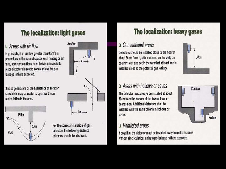
 Number of detectors : • The number of detectors required for an application depends on a number of factors: • plant layout, air flow pattern, type of gas to be monitored, degree of protection. . .
 ATMOSPHERIC TESTING
 Atmospheric Testing Sample When / Where? prior to entry top, middle & bottom continuously during entry** prior to re-entry Sample Why? stratification / weights / mix TOP MIDDLE BOTTOM -There may be no hazardous atmosphere within the space whenever any employee is inside the space
") Atmospheric Testing METHANE (lighter than air)
Atmospheric Testing METHANE (lighter than air)
 CARBON MONOXIDE (slightly lighter than air)") Atmospheric Testing METHANE (lighter than air) CARBON MONOXIDE (slightly lighter than air)
Atmospheric Testing METHANE (lighter than air) CARBON MONOXIDE (slightly lighter than air)
 CARBON MONOXIDE (slightly lighter than air) HYDROGEN SULFIDE") Atmospheric Testing METHANE (lighter than air) CARBON MONOXIDE (slightly lighter than air) HYDROGEN SULFIDE (heavier than air)
Atmospheric Testing METHANE (lighter than air) CARBON MONOXIDE (slightly lighter than air) HYDROGEN SULFIDE (heavier than air)
 Atmospheric Testing -Before an employee enters the space, the internal atmosphere shall be tested for the following conditions in the order given: Sample What? What Levels? – Oxygen content 19. 5 - 23. 5% – Combustible Gases 10% LEL – Toxic Gases Depends on gas type
 Testing recommendations for gas monitoring instrumentation. • How often gas monitoring instruments be tested and calibrated ?
 Testing recommendations for gas monitoring instrumentation • Gas monitoring instrumentation should be treated like any other piece of lifesaving equipment. • It should be tested and calibrated on a regular basis. • The safest approach to testing gas monitors is to function test or calibrate them prior to each day’s use (mines …) !
 When it comes to testing and calibrating gas monitoring equipment ? • • Things to consider : Instrument use Abuse experienced in the field Gas exposures in fields ( high levels ) • Operature use ( shocks or abuse …)
 Testing recommendations for gas monitoring instrumentation • A function test consists of • A calibration has become a exposing each sensor in the very simple, sometimes gas monitor to a known automated, process concentration of gas in excess • A calibration consists of of the lowest alarm set-point. exposing the instrument sensors • The instrument should to a known concentration of gas, respond to the gas making appropriate response concentration by going into adjustments to ensure the alarm instrument it reading accurately : • If the sensors do not respond to the applied gas: the • zero setting in a pure air and instrument will be calibrated span setting with a known … concentration of gas.
 Testing recommendations for gas monitoring instrumentation • ISC/OLDHAM recommend a regular test according to the using : before each day’s usage sensitivity must be tested on a known concentration of gas • and a minimum interval of calibration every 6 months ( industries) or every year (domestic market).
 Summary u Complete Systems ISC/OLDHAM provides complete Gas and flame detection, and dust monitoring systems for your applications. ISC/OLDHAM can supervise the installation of these systems and execute it’s Commissioning and start-up.