

230ff8b67ba362a79f6c6866207d2171.ppt
- Количество слайдов: 86
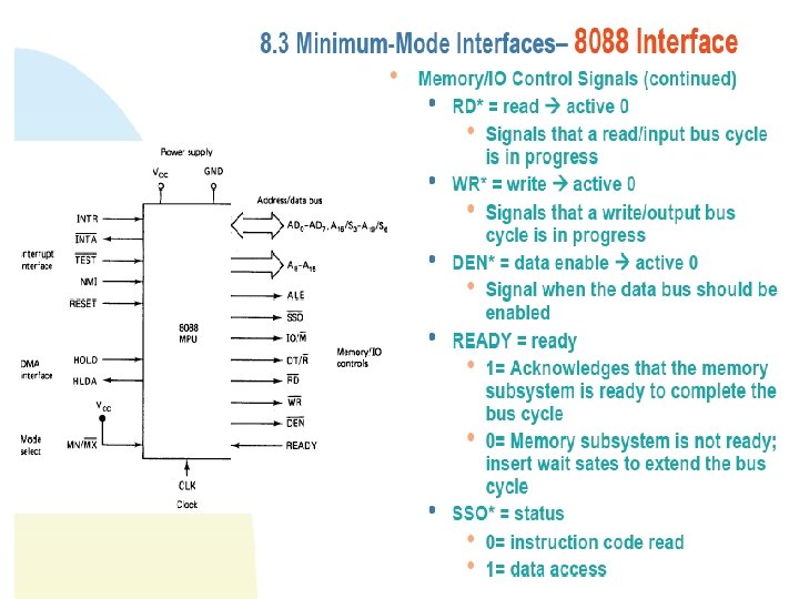
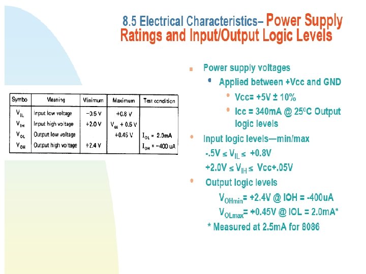
. S 6=0 always.") Fig 8 -4 p-341. S 5=IF flag (interrupt Enable). S 6=0 always.
Fig 8 -4 p-341. S 5=IF flag (interrupt Enable). S 6=0 always.
 SSO=during read cycle, it is identifies whether a code or data access is in progress.

 Types of I/O for 8088/8086 • Input/output system allows peripherals to: – Provide data or – Receive results after processing the data. • Implemented using I/O ports. • Employs two different types of I/O: – Isolated I/O. – Memory mapped I/O. • Method differs in how I/O ports are mapped into MPU’s address spaces. • Some microcomputer employs both method.
 Isolated I/O • I/O devices treated separately from memory. – Hardware and software architecture of 8088/8086 support separate memory I/O address space. • Can be accessed as either byte-wide or word-wide. • Can be treated as either independent byte-wide I/O ports or word-wide I/O ports. • Page 0: – Certain I/O instructions can only perform operations to ports in this part of the address range. – Other I/O instructions can input/output data for ports anywhere in the address space.
 Isolated I/O FFFF Port 65 535 I/O address space 00 FF 00 FE Port 254 . . . Page 0 Port 255. . . 0004 Port 4 0003 Port 3 0002 Port 2 0001 Port 1 0000 Port 1 (16 bit port) Port 0 (16 bit port)
 Isolated I/O • Advantages: – 1 MByte memory address space is available for use with memory. – Special instructions have been provided in the instruction set of 8088/8086 to perform isolated I/O input and output operations. • These instructions have been tailored to maximize I/O performance. • Disadvantages: – All input and output data transfers must take place between AL or AX register and the I/O port.
 Memory-mapped I/O • I/O devices is placed in memory address space of the microcomputer. – The memory address space is assigned to I/O devices. – MPU looks at the I/O port as though it is a storage location in memory. – Make use of instructions that affect data in memory rather than special input/output instructions.
 Memory-mapped I/O FFFFF : Memory address space : E 0 FFF E 0003 : : I/O ports : : E 0002 Port 3 E 0001 Port 2 E 0000 Port 1 : : I/O addresses Port 4095 : I/O ports : : : : 00001 00000 Port 1 (16 bit port) Port 0 (16 bit port)
 Memory-mapped I/O • Advantages: – Many more instructions and addressing modes are available to perform I/O operations. – I/O transfers can now take place between I/O port and internal registers other than just AL/AX. • Disadvantages: – Memory instructions tend to execute slower than those specifically designed for isolated I/O. – Part of the memory address space is lost.
 Isolated Input/Output Interface • The interface permits 8088/8086 microcomputers to communicate with the outside world. • The interface between MPU and I/O is similar to MPU and memory. • Input output data transfers also take place over the multiplexed address/data bus. • Through this I/O interface, the MPU can input or output data in bit, byte or word (8086) formats.
 Isolated Input Output Interface : : Minimum-mode Interface Minimum-mode 8088 system I/O interface
 Isolated Input Output Interface : : Minimum-mode Interface Minimum-mode 8086 system I/O interface
 Isolated Input Output Interface : : Minimum-mode Interface • Example of I/O device: – Keyboard (input). – Printer (output). – Asynchronous serial communications port (input/output). • Circuits in the interface section must perform functions such as: – Select I/O port. – Latch output data. – Sample input data. – Synchronize data transfers.
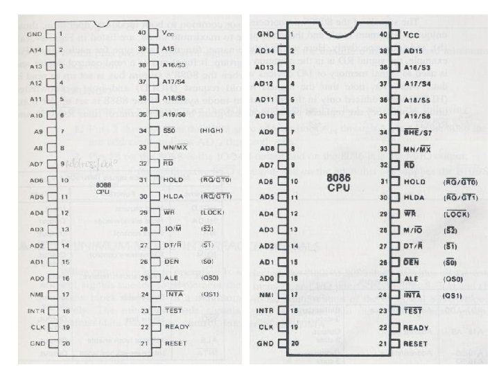
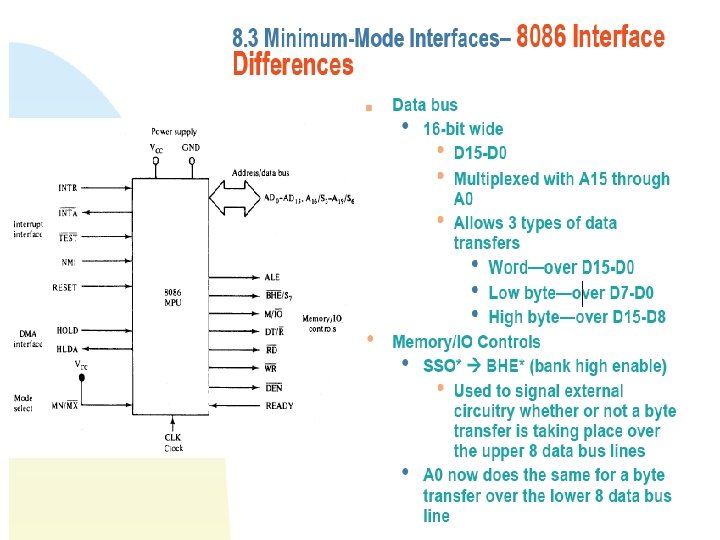
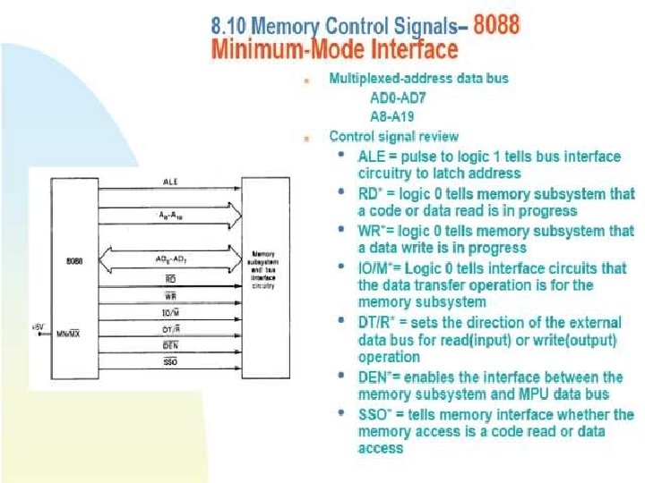
 • Data/Address Lines: – Multiplexed") Isolated Input Output Interface : : Minimum-mode Interface (8088) • Data/Address Lines: – Multiplexed address/data bus. – Only 16 least significant lines used. • AD 0 -AD 7 and A 8 -A 15. • Control Signals: – Similar to memory interface. • Difference between 8088 and 8086. – Complete data bus used for data transfer. • AD 0 -AD 15. – M/IO complement of IO/M. – SSO replaced with BHE.
Isolated Input Output Interface : : Minimum-mode Interface (8088) • Data/Address Lines: – Multiplexed address/data bus. – Only 16 least significant lines used. • AD 0 -AD 7 and A 8 -A 15. • Control Signals: – Similar to memory interface. • Difference between 8088 and 8086. – Complete data bus used for data transfer. • AD 0 -AD 15. – M/IO complement of IO/M. – SSO replaced with BHE.
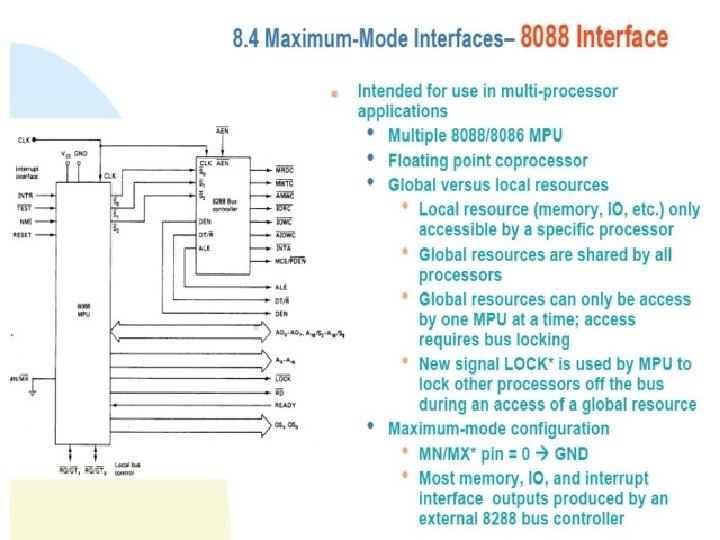
 Isolated Input Output Interface : : Maximum-mode Interface Maximum-mode 8088 system I/O interface Maximum-mode 8086 system I/O interface
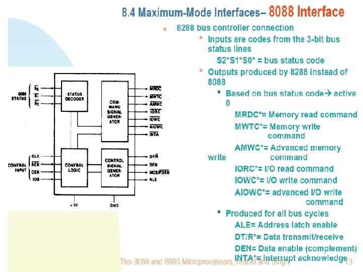
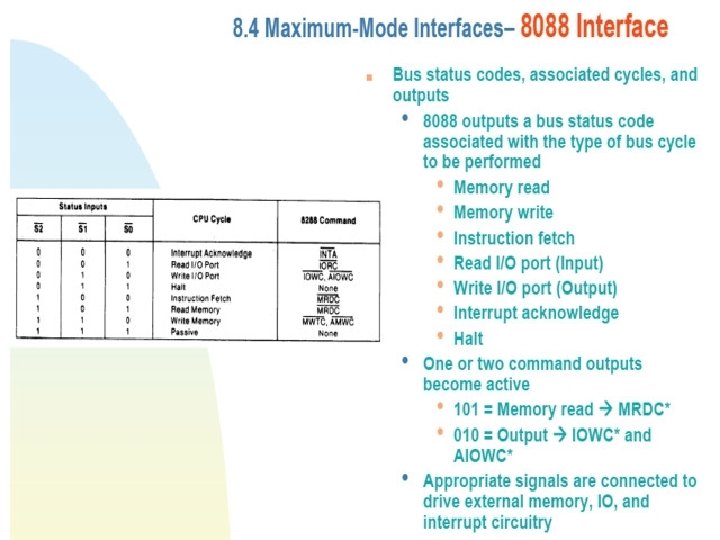
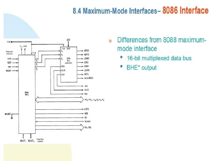
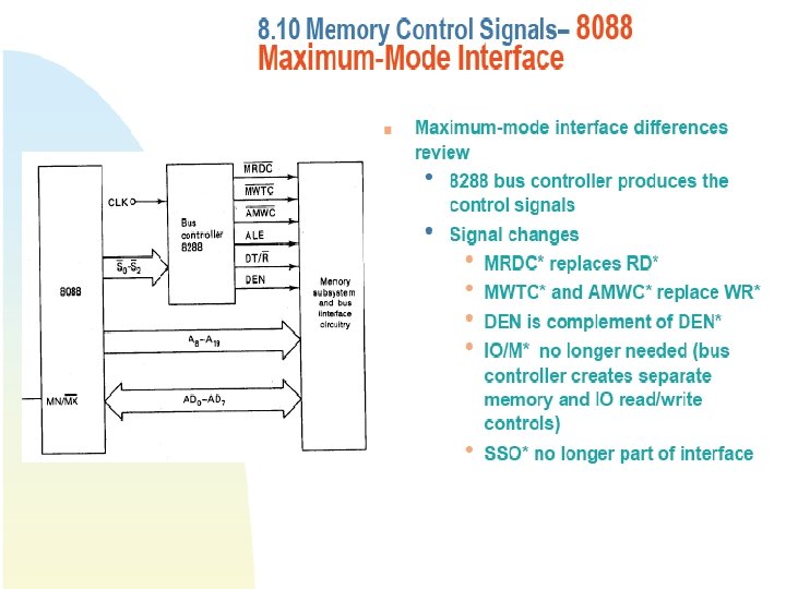
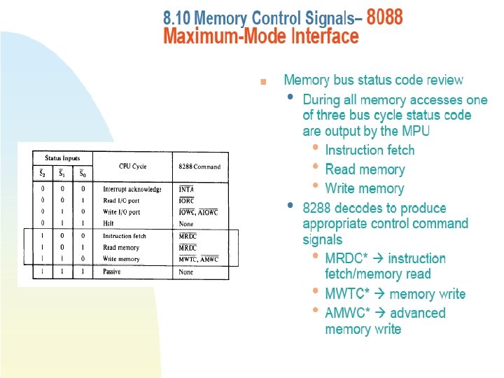
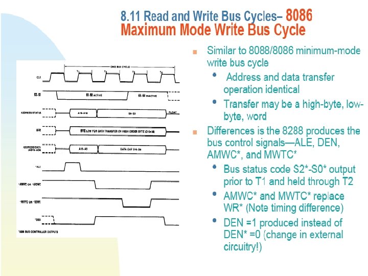
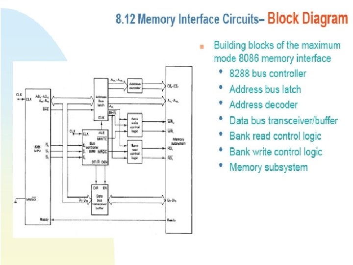
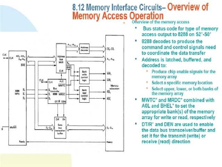
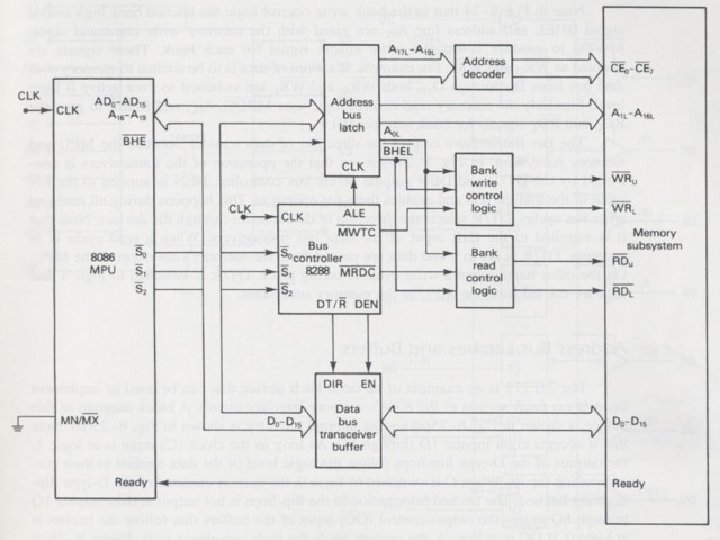
 • 8288 bus controller produces") Isolated Input Output Interface : : Maximummode Interface (8088/86) • 8288 bus controller produces control signals for the I/O subsystems. • Decoded S 2 S 1 S 0 will determine which type of bus cycle is in progress. • If code corresponds to: – I/O read bus cycle , 8288 generates IORC. – I/O write bus cycle, then IOWC and AIOWC generated. • 8288 also produces ALE, DT/R and DEN control signals. • Data and addresses are transferred over AD 0 -AD 7 and A 8 -A 15. • 8086 differs from 8088 as follows: – 16 bit data bus is the path for data transfers. – Signal BHE is included.
Isolated Input Output Interface : : Maximummode Interface (8088/86) • 8288 bus controller produces control signals for the I/O subsystems. • Decoded S 2 S 1 S 0 will determine which type of bus cycle is in progress. • If code corresponds to: – I/O read bus cycle , 8288 generates IORC. – I/O write bus cycle, then IOWC and AIOWC generated. • 8288 also produces ALE, DT/R and DEN control signals. • Data and addresses are transferred over AD 0 -AD 7 and A 8 -A 15. • 8086 differs from 8088 as follows: – 16 bit data bus is the path for data transfers. – Signal BHE is included.
 Input Output Data Transfers • Data transfers: – Byte-wide or word-wide. • I/O address used to select the input/output port to be accessed. – I/O address specified as part of the instruction that performs the I/O operation. • The addresses: – 16 bits in length. – Output over AD 0 (LSb) – AD 7 and A 8 -A 15 (MSb). • The most significant address lines A 16 -A 19 = 0 during address period (T 1) of all bus cycles. • IO/M determines I/O operations. Held at 1 during the complete input/output bus cycles.
. – Performed over data bus. –") Input Output Data Transfers • Data transfer (8088). – Performed over data bus. – Byte-wide transfers = 1 cycle (D 0 -D 7). – Word-wide transfers require two bus cycles. • Two consecutive byte-wide data transfers. • Data transfer (8086): – The addresses are output on address/data bus lines AD 0 -AD 15. – A 0 and BHE determine whether access at oddaddressed byte-wide port, even-addressed byte-wide port or word-wide port. • i. e. A 0 BHE = 10 odd-addressed byte wide I/O port is accessed.
Input Output Data Transfers • Data transfer (8088). – Performed over data bus. – Byte-wide transfers = 1 cycle (D 0 -D 7). – Word-wide transfers require two bus cycles. • Two consecutive byte-wide data transfers. • Data transfer (8086): – The addresses are output on address/data bus lines AD 0 -AD 15. – A 0 and BHE determine whether access at oddaddressed byte-wide port, even-addressed byte-wide port or word-wide port. • i. e. A 0 BHE = 10 odd-addressed byte wide I/O port is accessed.
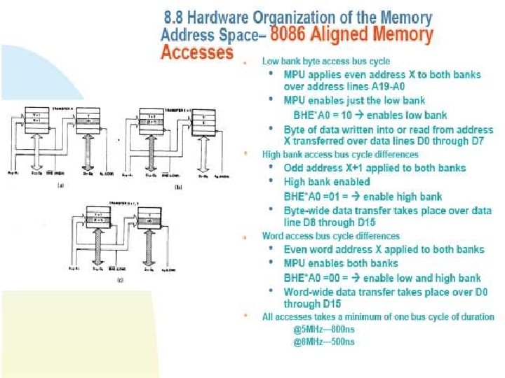
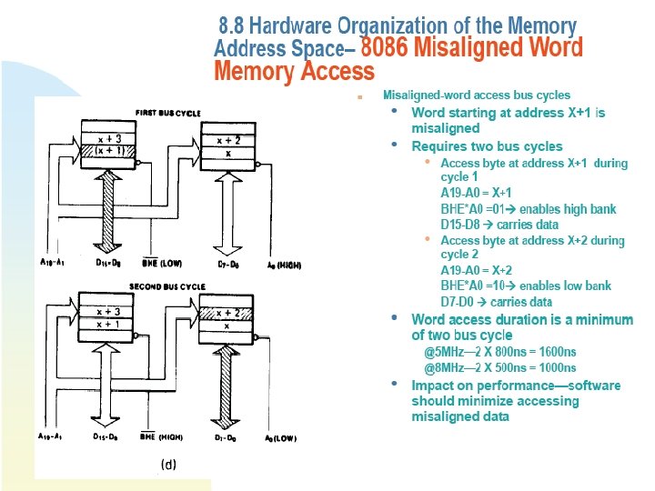
 Input Output Data Transfers – Even and odd addressed byte transfer require 1 bus cycle. • Even-addressed byte transfer D 0 -D 7. • Odd-addressed byte transfer D 8 -D 15. – Word data transfer can either require one or two bus cycles. • Word data transfer performed over D 0 -D 15. • One cycle word transfer I/O port is aligned at even address boundaries. • Two cycles word transfer Misaligned word.
 Input Output Instructions • Isolated I/O mode uses special input and output instructions together with I/O port addressing modes. • Can either be direct or variable I/O instructions. – Can be used to transfer byte/word. – All data transfer take place over I/O device and accumulator register (AL/AX). • Known as accumulator I/O. – Byte/word wide transfer determined by AL/AX.
 (Port)") Input Output Instructions Mnemonic Meaning Format Operation Input direct IN Acc, Prt (Acc) (Port) Acc = AL or AX Input indirect (variable) IN Acc, DX (Acc) ((DX)) Output direct OUT Prt, Acc (Port) (Acc) Output indirect (variable) OUT DX, Acc ((DX)) (Acc) IN OUT Input/output instructions
Input Output Instructions Mnemonic Meaning Format Operation Input direct IN Acc, Prt (Acc) (Port) Acc = AL or AX Input indirect (variable) IN Acc, DX (Acc) ((DX)) Output direct OUT Prt, Acc (Port) (Acc) Output indirect (variable) OUT DX, Acc ((DX)) (Acc) IN OUT Input/output instructions
 Input Output Instructions : : Direct I/O Instructions • Address of the I/O port: – Specified as part of the instruction. • 8 bits provided for direct address, thus: – Address range is limited to 0016 -FF 16. – This range is referred as page 0 in I/O address space. • i. e. IN AL, 0 FEH – (AL) (FE 16) – Content of address FE to be input to the AL register. – Only one bus cycle.
 Input Output Instructions : : Direct I/O Instructions • Example 2: – Write a sequence of instructions that will output the data 3416 to a byte-wide output port at address 8916 of the I/O address space.
 Input Output Instructions • Difference between direct and variable: – The way in which the address of the I/O port is specified. – Direct 8 bit address is specified as part of the instruction. – Variable use 16 bit address in DX register. • (DX) is not an offset but actual address. • Variable I/O instructions can access ports located anywhere in the 64 K byte I/O address space. • Data/address must be loaded into or removed from AL/AX/DX before another input or output operation can be performed.
 Input Output Instructions • Example 2: – Write a program that will output DA 16 to an output port located at address EA 2016 of the I/O address space. – Data are to be read in from two byte-wide input ports at address AA 16 and BA 16 and then output as a word-wide output port at address B 00016. Write a program to perform this input/output operation.
 similar to those involved in memory interface.") Input Output Bus Cycles • Signals (minimum-mode) similar to those involved in memory interface. • Function, logic levels and timing of all signals other than IO/M are identical to section 8. 11. • IO/M changes at logic level, not the timing.
Input Output Bus Cycles • Signals (minimum-mode) similar to those involved in memory interface. • Function, logic levels and timing of all signals other than IO/M are identical to section 8. 11. • IO/M changes at logic level, not the timing.
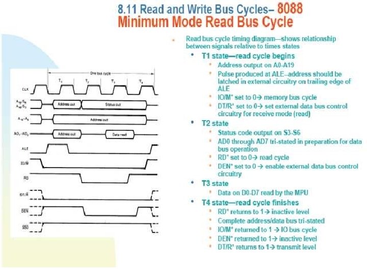
 Input Bus Cycles : : 8088 • T 1: – IO/M =1 and maintained throughout the cycle. • Indicate IO operation. – ALE output together with address. – DEN =0. • Signals interface circuitry when to put data onto the bus. • 8088 reads data off the bus during period T 3. Input bus cycle of the 8088
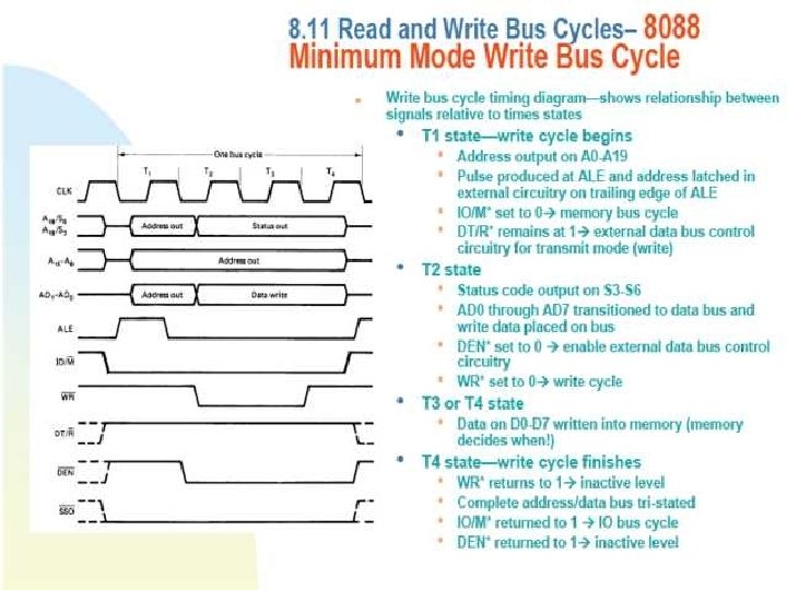
 Output Bus Cycles : : 8088 • 8088 puts data on the bus late in T 2 and maintains it during the rest of the bus cycle. • This time WR = 0. – Signals I/O system that valid data are on the bus. Output bus cycle of the 8088
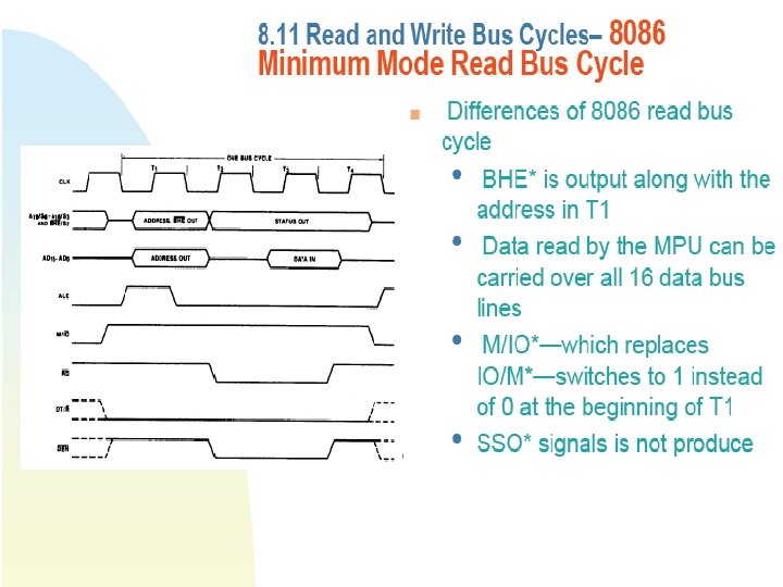
 Input Bus Cycles : : 8086 • Differences: – BHE output along with address in state T 1. • Used with A 0 to select even/odd address byte/word wide port. – Data transfer over 16 bit address/data bus at T 3. – M/IO replaces IO/M. – SSO = none. Refer figure 8 -52 & 8 -53


