

adb238c617acedd4210f11a0a6066c8a.ppt
- Количество слайдов: 58
 ERT 457 DESIGN OF AUTOMATION SYSTEMS SYSTEM DRIVES AND ACTUATOR Munira Mohamed Nazari PPK Bioproses, Uni. MAP
 Course Outcome CO 2 Ability to ANALYZE the actuator component and application of an automation system in Biosystems Engineering
 INTRODUCTION
 Why we automated systems in agricultural area? • To fulfill requirement of modern farming. – Reduce labor work and cost. – Reduce time. • Help you to improve your agricultural application to be even more productive and comfortable to use.
 Actuators • Actuator is used as a mechanism to induce or control motion in mechanical systems. They are devices which transform an input signal (usually electrical) into motion. Input Signal ACTUATOR Feedback Signal Output
 Actuators in agriculture • Actuator solutions in spreaders adjusting the amount of fertilizers. • Sprayer, actuator control height and angle of outlet nozzle. • In chopper, actuator used to adjust the outlet direction. • Electric actuators – used to improve ergonomics and comfort in a number of applications such as adjustment of steering wheels, seats and ventilation.
 Actuation Systems • Practically every industrial process requires objects to be moved, manipulated, held, or subjected to some type of force. • The most commonly employed methods for producing the required forces/motions are: – – Air – Pneumatics Liquids – Hydraulics Electrical – motors, solenoids. Mechanical
 HYDRAULIC ACTUATOR Cylinder or fluid motor that use hydraulic power to facilitate mechanical operation. The mechanical motion gives an output in terms of linear, rotary or oscillatory motion. Since liquid cannot be compressed, they take longer to gain speed and power while requiring more time to slow back down.
 Pneumatic energy is more desirable for main engine controls because it can quickly respond in starting and stopping as the power source does not need to be stored in reserve for operation. Convert energy formed by compressed air at high pressure into ether linear or rotary motion. PNUEMATIC ACTUATOR
 ELECTRICAL ACTUATORS Devices powered by motor that converts electrical energy to mechanical torque. The electrical energy is used to actuate equipment that requires multiturn valves like gate or globe valves. It is considered as one of the cleanest and readily available forms of actuator as it does not involve oil.
 MECHANICAL ACTUATOR Happen when a rotary motion is converted into linear motion to execute a movement. It involves gears, rails, pulley, chain and other devices to operate. Knowing the aforementioned information is essential so the correct type of actuator can be selected.
 Control Drive Actuator Type Electrical -") Drives & Control Engineering for Actuators Energy (Medium) Control Drive Actuator Type Electrical - Electrical current Contactor and relay Power control contactor Digital and analog control -Wired program -Freely programmable system DC motor AC motor Stepper motor Solenoid Pneumatics - Compressed air from compressor Digital control Conventional valve technology Solenoid Pneumatic logic Directional valve Flow control valve Motors Cylinders Tools-gripper Hydraulics - Hydraulic fluids using pump Mechanical driven Manual driven Solenoid Directional valve Flow control valve Special valve Motors Cylinders
Drives & Control Engineering for Actuators Energy (Medium) Control Drive Actuator Type Electrical - Electrical current Contactor and relay Power control contactor Digital and analog control -Wired program -Freely programmable system DC motor AC motor Stepper motor Solenoid Pneumatics - Compressed air from compressor Digital control Conventional valve technology Solenoid Pneumatic logic Directional valve Flow control valve Motors Cylinders Tools-gripper Hydraulics - Hydraulic fluids using pump Mechanical driven Manual driven Solenoid Directional valve Flow control valve Special valve Motors Cylinders
 A Brief System Comparison • The task considered is how to lift a body by a distance x mm. such tasks are common in manufacturing industries.
 Electric Actuators - motor
 Sensors vs. Actuators • Control systems requires sensors and actuators. – However, have their own characteristics.
 • Power/energy transduction – Sensor – Actuator Physical property Electrical/optical Physical/mechanical • Power density – Sensor • from potentially high power density to relative low power density (signal level)
 • Power density – Actuator • High power density conversion, use signal level (low power density) to modulate/control the power conversion.
 TYPES OF ACTUATORS
 Solenoids Motor Valves Actuators Pneumatic Cylinders Hydraulic
 Solenoids • Solenoids are the most common actuator components. The basic principle of operation is there is a moving ferrous core (a piston) that will move inside wire coil as shown in Figure 1: Solenoid
 • Normally the piston is held outside the coil by a spring. When a voltage is applied to the coil and current flows, the coil builds up a magnetic field that attracts the piston and pulls it into the center of the coil. The piston can be used to supply a linear force. • Well known applications of these include pneumatic values and car door openers.
 Valves • The flow of fluids and air can be controlled with solenoid controlled valves. An example of a solenoid controlled valve is shown in Figure 2: A Solenoid Controlled 5 Ported, 4 Way 2 Position Valve
 • The solenoid is mounted on the side. When actuated it will drive the central spool left. • The top of the valve body has two ports that will be connected to a device such as a hydraulic cylinder. • The bottom of the valve body has a single pressure line in the center with two exhausts to the side. • In the top drawing the power flows in through the center to the right hand cylinder port. The left hand cylinder port is allowed to exit through an exhaust port.
 • In the bottom drawing the solenoid is in a new position and the pressure is now applied to the left hand port on the top, and the right hand port can exhaust. • The symbols to the left of the figure show the schematic equivalent of the actual valve positions. • Valves are also available that allow the valves to be blocked when unused.
 • Valve symbols – Consists of a square for each of its switching positions. (eg: poppet valve – two position valve – two squares) Flow path Port labels: 1 or P = pressure supply 3 or T = hydraulic return 3 (R) or 5 (S) = pneumatic exhaust 2 (B) or 5 (A) = output Initial connections ( 4 ports) Flow shut-off
 • Different types of valves are: – 2 -way normally closed - these have one inlet, and one outlet. When unenergized, the valve is closed. When energized, the valve will open, allowing flow. These are used to permit flows. – 2 -way normally open - these have one inlet, and one outlet. When unenergized, the valve is open, allowing flow. When energized, the valve will close. These are used to stop flows. When system power is off, flow will be allowed. – 3 -way normally closed - these have inlet, outlet, and exhaust ports. When unenergized, the outlet port is connected to the exhaust port. When energized, the inlet is connected to the outlet port. These are used for single acting cylinders.
 – 3 -way normally open - these have inlet, outlet and exhaust ports. When unenergized, the inlet is connected to the outlet. Energizing the valve connects the outlet to the exhaust. These are used for single acting cylinders – 3 -way universal - these have three ports. One of the ports acts as an inlet or outlet, and is connected to one of the other two, when energized/unenergized. These can be used to divert flows, or select alternating sources. – 4 -way - These valves have four ports, two inlets and two outlets. Energizing the valve causes connection between the inlets and outlets to be reversed. These are used for double acting cylinders. **The n-way represents the number of outlets and inlets connections.
 • Some of the ISO symbols for valves are shown in Figure 3. When using the symbols in drawings the connections are shown for the unenergized state. • The arrows show the flow paths in different positions. The small triangles indicate an exhaust port.
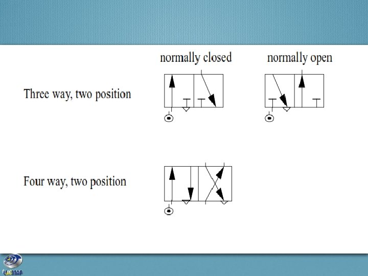
 • Valve actuation symbols.
 • Control Valve Sizing – Procedure of determining correct size of valve body. Flow rate Q = Av √ (∆P / ρ) Valve flow coefficient Density of the fluid Pressure drop across the valve Valve size (mm) Flow coefficient 480 640 800 960 1260 1600 1920 2560 Cv 8 14 22 30 50 75 110 200 Av x 10 -5 19 33 52 71 119 178 261 474 Table 7. 1
 • Example: – Consider the problem of determining the valve size for a valve that is required to control the flow of water when the maximum flow required is 0. 012 m³/s and the permissible pressure drop across the valve at this flow rate is 300 k. Pa. Density of water is 1000 kg/m³ Q = Av √ (∆P / ρ) Av = Q√ (ρ /∆P) = 0. 012√ (1000 / 300 x 10³) = 69. 3 x 10 -5 m² So, the valve size is 960 mm.
 Cylinders • Cylinders create linear force or motion by using pressurized air or fluid. When one side of the cylinder is pumped with fluid that side expands and a piston is moved. The fluid present on the other side of the piston should be moved out. • The force produced by the cylinder is proportional to the cross sectional area of the cylinder P = F/A, so F = PA • where – P represents pressure of the hydraulic fluid – A represents an area of the piston – F represents force produced from the piston rod
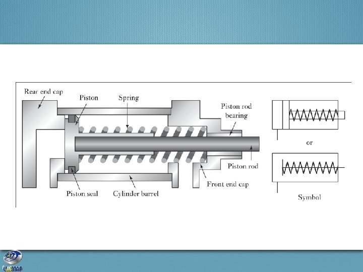
 Figure 3: A Cross Section of a Hydraulic Cylinder
 • Single acting cylinders apply force when extending and typically use a spring to retract the cylinder. • Double acting cylinders apply force in both direction. • Magnetic cylinders are often used that have a magnet on the piston head. When it moves to the limits of motion, reed switches will detect it.
 no current through solenoid, (b) a current") Control of a single-acting cylinder with (a) no current through solenoid, (b) a current through the solenoid. When a current passes through the solenoid, the valve switches position and pressure is applied to move the piston along the cylinder. When the current ceases, the valve reverts to its initial position and the air is vented from the cylinder.
Control of a single-acting cylinder with (a) no current through solenoid, (b) a current through the solenoid. When a current passes through the solenoid, the valve switches position and pressure is applied to move the piston along the cylinder. When the current ceases, the valve reverts to its initial position and the air is vented from the cylinder.
 not activated, (b) activated. Current through") Control of a double-acting cylinder with solenoid, (a) not activated, (b) activated. Current through one solenoid causes the piston to move in one direction with current through the other solenoid reversing the direction of motion.
Control of a double-acting cylinder with solenoid, (a) not activated, (b) activated. Current through one solenoid causes the piston to move in one direction with current through the other solenoid reversing the direction of motion.
 • The choice of cylinder, determined by force required to move the load and speed required. – Hydraulic – capable larger force – Pneumatic – capable greater speed FORCE Force produced by cylinder Working pressure F = Aρ Cross-sectional area of cylinder HYDRAULIC FLUID FLOW Q = Av Speed Can’t use for pneumatic !! -since its speed depends on the rate at which air can be vented ahead of the advancing piston.

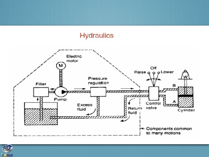
 Hydraulics • Hydraulics makes use of incompressible fluids to provide high force at limited motion ranges and low speed. • The hydraulic system normally uses an oil as the hydraulic fluid. It is used to lubricate the components of the hydraulic system. • This fluid is pressurized by a pump and then it is passed via valves and hoses in order to move the cylinders. • A pump present at the center of the system produces high pressures, which are transferred to a cylinder and transformed into linear force and displacement. • The hydraulic system can be mainly used in high power applications.
 • Hydraulic systems components: – – – normally contain the Hydraulic fluid An oil reservoir A pump to move oil and apply pressure Pressure lines Control valves – to regulate fluid flow Piston and cylinder – to actuate external mechanisms following
 • The hydraulic fluid is often a noncorrosive oil chosen so that it lubricates the components. This is normally stored in a reservoir as shown below.
 • Fluid is drawn from the reservoir to a pump where it is pressurized. This is normally a geared pump so that it may deliver fluid at high pressure at a constant flow rate. • A flow regulator is normally placed at the high pressure outlet from the pump. If fluid is not flowing in other parts of the system this allow fluid to recirculate back to the reservoir to reduce wear on the pump. • The high pressure fluid is delivered to solenoid controlled vales that can switch fluid flow on or off. • From the vales fluid will be delivered to the hydraulics at high pressure, or exhausted back to the reservoir.
 Hydraulic systems can be very effective for high power applications, but the use of fluids and high pressures can make this method awkward, messy and noisy for other applications.
 Pneumatics • A pneumatic system and the hydraulic system are similar in many respects. With the pneumatic system, it avoids the use of reservoir as air is not collected and stored in the system. It is mainly used in low force applications. • The pneumatic system has following features: – – It is light in weight It produces pressures up to 85 psi Dampers are used to absorb the impact at ends of the cylinder It is provided with an additional equipment for pressurized air supply.
 • The operating environments should be verified with extreme care while designing the pneumatic system. • In particular the elevation above sea level will result in a dramatically different air pressure. • Other operating environments such as in submersibles, the air pressure might be higher than at sea level.
 • Symbol for pneumatic systemsece – Flow control valve • Used to restrict the flow, typically to slow motion – Shuttle valve • Allows flow in one direction, but blocks in the other. – Receiver tank • Allows pressurized air to be accumulated. – Dryer • Help remove dust and moisture from the air, prolonging the life of the valves and cylinders.
 – Filter • Help remove dust and moisture from the air, prolonging the life of the valves and cylinders – Pump – Pressure regulator
 Motors • Motors are also commonly used actuators. However, they do not have significant properties for applications involving logical control. • Low current motors are controlled by switching with a PLC and high power motors by using a motor starter or a relay.
 Others • There are many other types of actuators including those on the brief list below. – Heaters • Heaters are switched on and off to maintain the temperature within a particular range. A relay is used to control the heaters. – Lights • Lights are directly linked to the PLC and are found in all machines in order to give the proper feedback to operators and indicate the state of the machine. – Sirens/horns • Sirens or horns are also linked to the PLC and are used for risky or unattended machines.
 SUMMARY
 • Solenoids can be used to convert an electric current to a limited linear motion. • Hydraulics and pneumatics use cylinders to convert fluid and gas flows to limited linear motion. • Solenoid valves can be used to redirect fluids and gas flows. • Pneumatics provides smaller forces at higher speeds, but is not stiff. Hydraulics provides large forces and is rigid, but a lower speeds. • Many other types of actuators can be used.
 PRACTICE PROBLEMS
 • A hydraulic cylinder is to be used to move a workpiece in a manufacturing operation through a distance of 50 mm in 10 s. A force of 10 k. N is required to move the workpiece. Determine the required working pressure and hydraulic liquid flow rate if a cylinder with a piston diameter of 100 mm is available. P = 1. 27 Mpa & Q = 3. 93 x 10 -5 m³/s
 • What is the process control valve size for a valve that is required to control the flow of water when the maximum flow required is 0. 002 m³/s and the permissible pressure drop across the valve at this flow rate is 100 k. Pa? The density of water is 1000 kg/m³. The process control valve size = 480 mm
 THANK YOU…