ccfa214cec79ac7bb43b263b8d1dc7a3.ppt
- Количество слайдов: 57


ERT 210/4 Process Control CHAPTER 8 Feedback Controllers Hairul Nazirah bt Abdul Halim Email: hairulnazirah@unimap. edu. my Office: 04 -9798840

Exxon. Mobil Chemical Plant

Process Control in our daily life…

Process Control in our daily life… • Controlling the water temperature of a shower • Let’s analyze this process: Control objective: to control the shower temp. process: shower sensor: person’s skin Controlled variable (CV): shower temp. Set point: desired shower temp. Manipulated variable (MV): flow of cold water Final control element: valve on cold water line Controller: person in the shower

• Benefits of improved process control: 1. improve product quality 2. faster 3. greater production rates 4. less expensive process validation procedure

Overview – Temperature Control • heat exchanger - uses steam to heat cold water. • How to control the temperature? ? Manual Control Automatic Control

MANUAL CONTROL Operator Compare Temp. with desired value open/close valve To admit more/less steam
 (transmits it to electronic signal) FEEDBACK")
AUTOMATIC CONTROL SENSOR - TRANSMITTER (measure the temperature) (transmits it to electronic signal) FEEDBACK CONTROLLER (compares the measured temp. to the set point value & make corrective action) I/P TRANSDUCER (Convert electronic signal to pneumatic signal) CONTROL VALVE (Receive signal & adjust the manipulated variables (flow))

COURSE OUTCOME: CH 8, 9 & 10 CO 2: Ability to identify, measure and investigate Feedback controllers, Control system instrumentation and the control system design.
,")
CHAPTER 8: FEEDBACK CONTROLLERS DEFINE and DISCUSS the standard feedback control algorithm (control laws), IDENTIFY and COMPARE Proportional-integral-derivative (PID) control and on-off control types of feedback control Subtopic: 1. 2. 3. 4. Definition Basic Control Modes PID Controllers On-Off Controllers

Chapter 8 Feedback Controllers Figure 8. 1 Schematic diagram for a stirred-tank blending system.

Chapter 8 • Basic components in a feedback control loop are: 1. Process being control (blending system) 2. Sensor-transmitter combination (AT) 3. Feedback controller (AC) 4. Current-to-pressure transducer (I/P) 5. Final control element (control valve) 6. Transmission line between the various instrument

BLOCK DIAGRAM OF A FEEDBACK CONTROL SYSTEM Figure 11. 7 Block diagram for the entire blending process composition control system.

INDUSTRIAL PROCESS CONTROL EXAMPLES • • Flow Controller Level Control in a tank Aerobic Fermentation Process Fed-Batch Bioreactor

FLOW CONTROLLER • • Control objective: to maintain the desired flow rate The setpoint: desired flow rate Controlled variable (CV): the outlet flow rate Manipulated variable (MV): the inlet flow rate of the process stream Disturbances variable (DV): changes in the upstream pressure for the process stream Sensor: combination of an orifice plate and a device that measure a pressure drop across the orifice, which directly related to the flow rate. Final control element: the control valve in the line Controller – flow controller (FC) – compares the measured flow rate with the specified flow rate (flow setpoint) and opens/closes the control valve accordingly.

Chapter 8 Figure 8. 2 Flow control loop

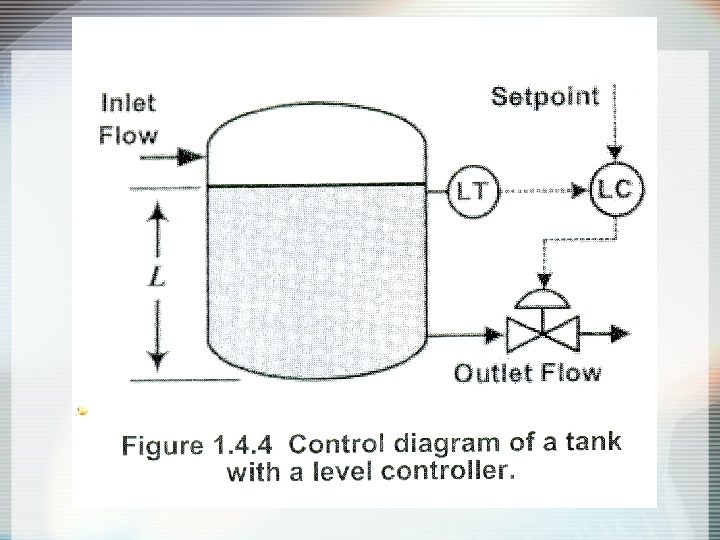
LEVEL CONTROL IN A TANK • • • Control objective: to maintain the level in the tank The setpoint: desired level in the tank Controlled variable (CV): the level in the tank Manipulated variable (MV): exit flow from the tank Disturbances variable (DV): changes in the inlet flow rate • Sensor: level indicator on the tank (LT) • Final control element: the control valve on the outflow line • Controller – level controller (LC) – compares the measured level with the setpoint for the level in the tank and makes a change to the control valve on the exit flow from the tank.
 conc.")
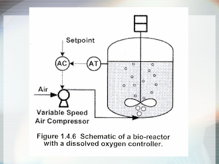
AEROBIC FERMENTATION PROCESS • Control objective: to maintain a specified dissolved oxygen (DO) conc. in the fermentation reactor so that the cells in the process have adequate oxygen levels. • The setpoint: desired DO concentration • Controlled variable (CV): the DO conc. in the fermentor • Manipulated variable (MV): air flow rate to the fermentor • Disturbances variable (DV): changes in the rpm of the mixer impeller • Sensor: DO sensor-transmitter (AT) • Controller – DO controller (AC) – compares the measured DO with the setpoint value and sets the air flow rate to the fermentor. • Final control element: variable speed air compressor

FED-BATCH BIOREACTOR • Control obj: to maintain a specified cell concentration in the bioreactor. • What is the CV, MV, DV, sensor & final control element?

• Control objective: to maintain a specified cell concentration in the bioreactor. • The setpoint: desired cell concentration • Controlled variable (CV): the cell conc. in the bioreactor • Manipulated variable (MV): the feed rate of glucose and nutrients mixture to the bioreactor. • Disturbances variable (DV): changes in the concentration of glucose in the feed. • Sensor: turbidity meter (AT) which provides a measurement that correlates with the cell conc. in the broth. • Controller – controller (AC) – compares the measured cell conc. with the setpoint value and sets the glucose feed rate. • Final control element: variable speed pump
 Proportional Control 2) Integral")
BASIC CONTROL MODES Three basic control modes: Chapter 8 1) Proportional Control 2) Integral Control 3) Derivative Control Next, we consider : Proportional-Integral-Derivative (PID) Control

PROPORTIONAL CONTROL Chapter 8 Objective: To reduce the error signal to zero.

Chapter 8 For proportional control, the controller output is proportional to the error signal, where:

Chapter 8

Some controllers have a proportional band setting instead of a controller gain. Chapter 8 The proportional band PB (in %) is defined as PB correspond to Kc and vice versa

Chapter 8 The transfer function for proportional-only control:

Disadvantage of proportional-only control: Chapter 8 Offset : Steady-state error occurs after a setpoint change or a sustained disturbance. -Offset can be eliminated by manually resetting the set point, ysp or by using controller with integral action. Applications • P-only control: for process with non-sluggish dynamic behavior & offset is not important. (pressure @ level)

INTEGRAL CONTROL Chapter 8 Controller output depends on the integral of the error signal over time. = Integral Time (adjustable parameter) - units of time (min)
 Control Integral control action is widely used: elimination of offset.")
Chapter 8 Proportional-Integral (PI) Control Integral control action is widely used: elimination of offset. Integral control action is normally used in conjunction with proportional control as the proportional-integral (PI) controller:

Chapter 8 Transfer function for the PI controller:

Chapter 8 • Response to unit step change in e: Figure 8. 6. Response of PI controller to unit step change in e(t).

Disadvantage of integral control: Chapter 8 Tend to produce oscillatory responses of the controlled variable. -Oscillatory response can be eliminated by proper tuning of the controller or by including derivative action. Applications • PI control: when offset elimination is important (Flow, Temp. , Composition, DO)

RESET WIND-UP Chapter 8 • When a control loop is in control with a minimal error, then wind-up is not a problem. • Wind-up is only a problem when a control loop is temporarily taken out of control. • Occur during start-up of a batch process or after a large set-point change. • The integral term becomes quite large due to a sustained error • The controller output eventually saturates.

RESET WIND-UP Chapter 8 • Further build-up of integral term while the controller is saturated. • undesirable because the controller is already doing all it can to reduce the error. • Commercial controllers provide antireset wind-up. • Antireset wind-up reduce the windup by temporarily halting the integral control action whenever the controller output saturates.

Chapter 8 Reset windup

DERIVATIVE CONTROL Chapter 8 anticipate the future behavior of the error signal by considering its rate of change. • ideal derivative action, = derivative time, has units of time.

Chapter 8 • “ideal” PD controller has the transfer function: • Derivative control action tends to improve dynamic response of the controlled variable • The process measurement is noisy if it contains high frequency or random fluctuations. • Disadvantage: derivative action will amplify the noise unless the measurement is filter

Chapter 8 • the transfer function for “real” PD controller, • Eq. 8 -12 includes a derivative filter that reduces the sensitivity of the calculations to high frequency noise in the measurement. • the value of α constant : 0. 05 < α <0. 2, (0. 1 being a common choice)
 Control Chapter 8 Combination of P, I & D Control modes 3")
Proportional-Integral-Derivative (PID) Control Chapter 8 Combination of P, I & D Control modes 3 most common forms of PID Control: 1. Parallel 2. Series 3. Expanded

Chapter 8 Parallel Form of PID Control Figure 8. 8 Block diagram of the parallel form of PID control (without a derivative filter)

Parallel Form of PID Control Chapter 8 Transfer function for “Ideal” PID control is: Transfer function for “Real” PID control, with derivative filter is:

Series Form of PID Control Chapter 8 Transfer function for “Ideal” PID control is: Figure 8. 9 Block diagram of the series form of PID control (without a derivative filter)

Series Form of PID Control Chapter 8 Commercial versions of the series-form controller have a derivative filter @ “Real PID control”:

Expanded Form of PID Control Use in MATLAB Chapter 8 Control parameters are 3 gains: Kc, KI and KD
. - Offset with")
Controller Comparison Chapter 8 P - Simplest controller to tune (Kc). - Offset with sustained disturbance or setpoint change. PI - More complicated to tune (Kc, I). Better performance than P No offset Most popular FB controller PID - Most complicated to tune (Kc, I, D). Better performance than PI No offset Derivative action may be affected by noise
, depends")
Chapter 8 Automatic and Manual Control Modes Automatic Mode • Controller output, p(t), depends on e(t), controller constants, and type of controller used. ( PI vs. PID etc. )
, is adjusted manually. • Manual Mode")
Chapter 8 Manual Mode • Controller output, p(t), is adjusted manually. • Manual Mode is very useful when unusual conditions exist: i) plant start-up ii) plant shut-down iii) emergencies

On-Off Controllers Chapter 8 • • • Simple type of feedback controllers Cheap Used in residential heating and domestic refrigerators Limited use in process control due to continuous cycling of controlled variable Less widely used than PID controllers – not versatile @ effective. Two mode of control action: 1. Full control action 2. No control action

On-Off Controllers Chapter 8 • Consider Figure 1. 6. 1 • The on-off heater applies heat to the system as long as the controlled temperature is below a specified upper limit. • When upper limit is reached, the addition of heat is stopped. • Heat is not added to the process until the controlled temp. becomes less than a specified lower limit

Chapter 8 • Figure 1. 6. 1 An example of the operation of an on-off temperature controller.

Chapter 8 Typical Response of Feedback Control Systems No control: the process slowly reaches a new steady state P – speed up the process response & reduces the offset PI – eliminate offset & the response more oscillatory PID – reduces degree of oscillation and the response time Figure 8. 12. Typical process responses with feedback control.

Chapter 8 Figure 8. 13. Proportional control: effect of controller gain. -Increasing Kc tends to make the process response less sluggish (more faster) -Too large of Kc, results in undesirable degree of oscillation or even become unstable -Intermediate value of Kc usually results in the best control.
 effect of reset time (b) effect")
Chapter 8 Figure 8. 14. PI control: (a) effect of reset time (b) effect of controller gain. -Increasing τI tends to make the process response more sluggish (slower) -Too large of τI, the controlled variable will return to the set point very slowly after a disturbance change @ set-point change occurs.

Chapter 8 Figure 8. 15. PID control: effect of derivative time. -Increasing τD tends to improve the process response by reducing the maximum deviation, response time and degree of oscillation. -Too large of τD: measurement noise is amplified and process response more oscillatory. -The intermediate value of τD is desirable.

Selection of Controller • Should consider the combination of dynamic behavior of: - final control element - process - sensor • P-only control: for process with non-sluggish dynamic behavior & offset is not important. (pressure @ level) • PI control: when offset elimination is important (Flow, Temp. , Composition, DO) • PID: for sluggish process (Biomass Concentration, Temp. , Composition)
ccfa214cec79ac7bb43b263b8d1dc7a3.ppt