
Emergency operation (Malfunction of electronic controller) Model LXE


emergency_operation1.ppt
- Размер: 16.4 Mегабайта
- Количество слайдов: 5
Описание презентации Emergency operation (Malfunction of electronic controller) Model LXE по слайдам
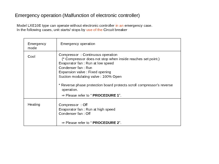
Emergency operation (Malfunction of electronic controller) Model LXE 10 E type can operate without electronic controller in an emergency case. In the following cases, unit starts/ stops by use of the Circuit breaker Emergency mode Cool Heating Emergency operation Compressor : Continuous operation (* Compressor does not stop when inside reaches set point. ) Evaporator fan : Run at low speed Condenser fan : Run Expansion valve : Fixed opening Suction modulating valve : 100% Open * Reverse phase protection board protects scroll compressor’s reverse operation. ⇒ Please refer to “ PROCEDURE 1 ”. Compressor : Off Evaporator fan : Run at high speed Condenser fan : Off ⇒ Please refer to “ PROCEDURE 2 ”.
Procedure 1 : For cooling operation Step 1 : Setting of electronic controller Step 2 : Setting of Electronic expansion valve Step 3 : Setting of Suction modulating valve Step 1 -1 Find connector on the back of electronic controller Emergency connector 1 and 2 (For COOL / HEAT) Emergency connector receptacle CN 5 : Power supply connector
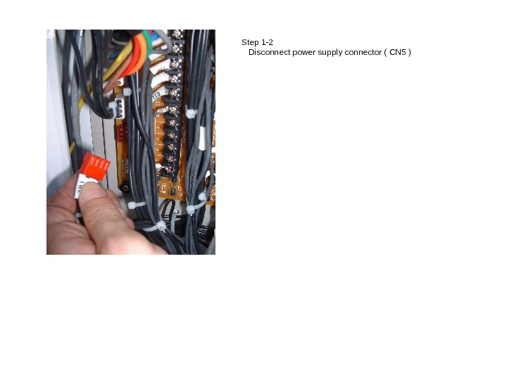
Step 1 -2 Disconnect power supply connector ( CN 5 )
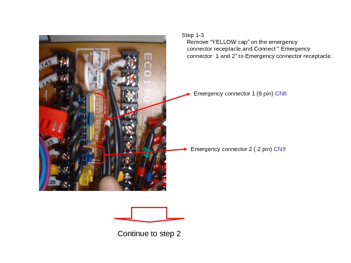
Step 1 -3 Remove “YELLOW cap” on the emergency connector receptacle and Connect “ Emergency connector 1 and 2” to Emergency connector receptacle. Emergency connector 1 (8 pin) CN 8 Emergency connector 2 ( 2 pin) CN 9 Continue to step
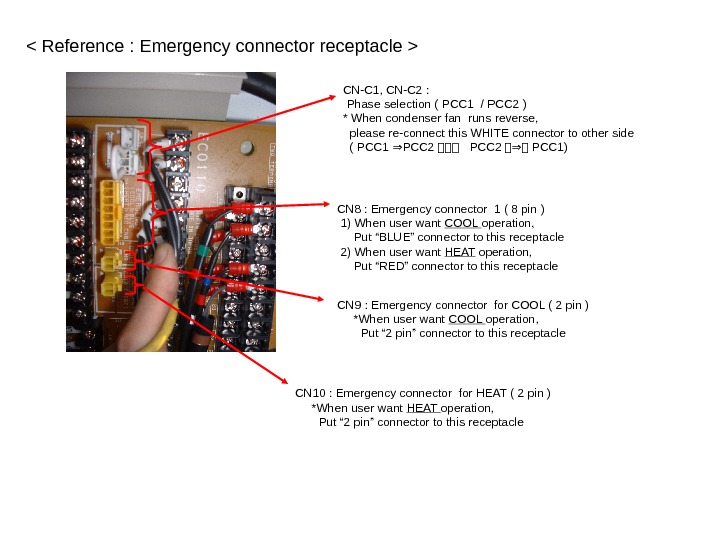
CN-C 1, CN-C 2 : Phase selection ( PCC 1 / PCC 2 ) * When condenser fan runs reverse, please re-connect this WHITE connector to other side ( PCC 1 PCC 2⇒ PCC 2 ⇒ PCC 1) CN 8 : Emergency connector 1 ( 8 pin ) 1) When user want COOL operation, Put “BLUE” connector to this receptacle 2) When user want HEAT operation, Put “RED” connector to this receptacle CN 9 : Emergency connector for COOL ( 2 pin ) *When user want COOL operation, Put “ 2 pin” connector to this receptacle CN 10 : Emergency connector for HEAT ( 2 pin ) *When user want HEAT operation, Put “ 2 pin” connector to this receptacle