007494dc963e7556e9b20f49793a546a.ppt
- Количество слайдов: 144

EC 6503 TRANSMISSION LINES AND WAVEGUIDES BY H. UMMA HABIBA, Professor SVCE, Chennai.

Overview of syllabus OBJECTIVES ü To introduce the various types of transmission lines and to discuss the losses associated. ü To give thorough understanding about impedance transformation and matching. ü To use the Smith chart in problem solving. ü To impart knowledge on filter theories and waveguide theories

Overview of syllabus OUTCOMES üUpon completion of the course, students will be able to Discuss the propagation of signals through transmission lines. ü Analyze signal propagation at Radio frequencies. ü Explain radio propagation in guided systems. ü Utilize cavity resonators

Overview of syllabus TEXT BOOK 1. John D Ryder, “Networks lines and fields”, Prentice Hall of India, New Delhi, 2005 REFERENCES 1. William H Hayt and Jr John A Buck, “Engineering Electromagnetics” Tata Mc Graw-Hill Publishing Company Ltd, New Delhi, 2008 2. David K Cheng, “Field and Wave Electromagnetics”, Pearson Education Inc, Delhi, 2004 3. John D Kraus and Daniel A Fleisch, “Electromagnetics with Applications”, Mc Graw Hill Book Co, 2005 4. GSN Raju, “Electromagnetic Field Theory and Transmission Lines”, Pearson Education, 2005 5. Bhag Singh Guru and HR Hiziroglu, “Electromagnetic Field Theory Fundamentals”, Vikas Publishing House, New Delhi, 2001. 6. N. Narayana Rao, “ Elements of Engineering Electromagnetics” 6

Overview of syllabus UNIT I -TRANSMISSION LINE THEORY General theory of Transmission lines - the transmission line - general solution - The infinite line - Wavelength, velocity of propagation - Waveform distortion - the distortion-less line Loading and different methods of loading - Line not terminated in Z 0 - Reflection coefficient - calculation of current, voltage, power delivered and efficiency of transmission - Input and transfer impedance - Open and short circuited lines - reflection factor and reflection loss.

Overview of syllabus UNIT II -HIGH FREQUENCY TRANSMISSION LINES Transmission line equations at radio frequencies - Line of Zero dissipation - Voltage and current on the dissipationless line, Standing Waves, Nodes, Standing Wave Ratio Input impedance of the dissipation-less line - Open and short circuited lines - Power and impedance measurement on lines - Reflection losses - Measurement of VSWR and wavelength.

Overview of syllabus UNIT III-IMPEDANCE MATCHING IN HIGH FREQUENCY LINES Impedance matching: Quarter wave transformer Impedance matching by stubs - Single stub and double stub matching - Smith chart - Solutions of problems using Smith chart - Single and double stub matching using Smith chart.

Overview of syllabus UNIT IV-PASSIVE FILTERS Characteristic impedance of symmetrical networks - filter fundamentals, Design of filters: Constant K Low Pass, High Pass, Band Elimination, m- derived sections - low pass, high pass composite filters.

Overview of syllabus UNIT V -WAVE GUIDES AND CAVITY RESONATORS General Wave behaviours along uniform Guiding structures, Transverse Electromagnetic waves, Transverse Magnetic waves, Transverse Electric waves, TM and TE waves between parallel plates, TM and TE waves in Rectangular wave guides, Bessel‟s differential equation and Bessel function, TM and TE waves in Circular wave guides, Rectangular and circular cavity Resonators.

UNIT I TRANSMISSION LINE THEORY UNIFORM PLANE WAVES

Transmission Line Properties § Has two conductors running parallel § Can propagate a signal at any frequency (in theory) § Becomes lossy at high frequency § Can handle low or moderate amounts of power § Does not have signal distortion, unless there is loss § May or may not be immune to interference § Does not have Ez or Hz components of the fields (TEMz) Coaxial cable (coax) Twin lead (shown connected to a 4: 1 impedance-transforming balun)

Transmission Line (cont. ) CAT 5 cable (twisted pair) The two wires of the transmission line are twisted to reduce interference and radiation from discontinuities.

Transmission Line (cont. ) Transmission lines commonly met on printed-circuit boards w er er h w Microstrip w Stripline w er w h Coplanar strips h er Coplanar waveguide (CPW) h

Transmission Line (cont. ) Transmission lines are commonly met on printed-circuit boards. Microstrip line A microwave integrated circuit

Fiber-Optic Guide Properties § Uses a dielectric rod § Can propagate a signal at any frequency (in theory) § Can be made very low loss § Has minimal signal distortion § Very immune to interference § Not suitable for high power § Has both Ez and Hz components of the fields

Fiber-Optic Guide (cont. ) Two types of fiber-optic guides: 1) Single-mode fiber Carries a single mode, as with the mode on a transmission line or waveguide. Requires the fiber diameter to be small relative to a wavelength. 2) Multi-mode fiber Has a fiber diameter that is large relative to a wavelength. It operates on the principle of total internal reflection (critical angle effect).

Fiber-Optic Guide (cont. ) Higher index core region http: //en. wikipedia. org/wiki/Optical_fiber

Waveguides Properties § Has a single hollow metal pipe § Can propagate a signal only at high frequency: > c § The width must be at least one-half of a wavelength § Has signal distortion, even in the lossless case § Immune to interference § Can handle large amounts of power § Has low loss (compared with a transmission line) § Has either Ez or Hz component of the fields (TMz or TEz) http: //en. wikipedia. org/wiki/Waveguide_(electromagnetism)

Transmission-Line Theory § Lumped circuits: resistors, capacitors, inductors neglect time delays (phase) § Distributed circuit elements: transmission lines account for propagation and time delays (phase change) We need transmission-line theory whenever the length of a line is significant compared with a wavelength.
![Transmission Line 2 conductors 4 per-unit-length parameters: C = capacitance/length [F/m] L = inductance/length Transmission Line 2 conductors 4 per-unit-length parameters: C = capacitance/length [F/m] L = inductance/length](https://present5.com/presentation/007494dc963e7556e9b20f49793a546a/image-20.jpg)
Transmission Line 2 conductors 4 per-unit-length parameters: C = capacitance/length [F/m] L = inductance/length [H/m] R = resistance/length [ /m] G = conductance/length [ /m or S/m] Dz

Transmission Line (cont. ) B i(z, t) RDz x x x +++++++ ----- LD z i(z+ z, t) + + v(z, t) GD z CDz v(z+ z, t) - - z 21

Transmission Line (cont. ) i(z, t) RDz LD z i(z+ z, t) + + v(z, t) GD z CDz v(z+ z, t) - - z 22

TEM Transmission Line (cont. ) Hence Now let Dz 0: “Telegrapher’s Equations” 23

TEM Transmission Line (cont. ) To combine these, take the derivative of the first one with respect to z: Switch the order of the derivatives. 24

TEM Transmission Line (cont. ) Hence, we have: The same equation also holds for i. 25

TEM Transmission Line (cont. ) Time-Harmonic Waves: 26

TEM Transmission Line (cont. ) Note that = series impedance/length = parallel admittance/length Then we can write: 27

TEM Transmission Line (cont. ) Let Then Solution: is called the "propagation constant. " Convention: 28

TEM Transmission Line (cont. ) Forward travelling wave (a wave traveling in the positive z direction): The wave “repeats” when: Hence: 29

Phase Velocity Track the velocity of a fixed point on the wave (a point of constant phase), e. g. , the crest. vp (phase velocity) 30

Phase Velocity (cont. ) Set In expanded form: Hence 31

Characteristic Impedance Z 0 I+ (z) + V+(z) - z A wave is traveling in the positive z direction. so (Z 0 is a number, not a function of z. ) 32

Characteristic Impedance Z 0 (cont. ) Use Telegrapher’s Equation: so Hence 33

Characteristic Impedance Z 0 (cont. ) From this we have: Using We have Note: The principal branch of the square root is chosen, so that Re (Z 0) > 0. 34

General Case (Waves in Both Directions) Note: wave in +z direction wave in -z direction 35

Backward-Traveling Wave I - (z) + V -(z) - z A wave is traveling in the negative z direction. so Note: The reference directions for voltage and current are the same as for the forward wave. 36

General Case I (z) + V (z) - Most general case: z A general superposition of forward and backward traveling waves: Note: The reference directions for voltage and current are the same forward and backward waves. 37

Summary of Basic TL formulas guided wavelength g phase velocity vp 38

Lossless Case so (real and indep. of freq. ) (indep. of freq. )

Lossless Case (cont. ) In the medium between the two conductors is homogeneous (uniform) and is characterized by ( then we have that , ), (proof given later) The speed of light in a dielectric medium is Hence, we have that The phase velocity does not depend on the frequency, and it is always the speed of light (in the material). 40

Terminated Transmission Line Terminating impedance (load) Ampl. of voltage wave propagating in positive z direction at z = 0. Ampl. of voltage wave propagating in negative z direction at z = 0. Where do we assign z = 0? The usual choice is at the load. Note: The length l measures distance from the load: 41

Terminated Transmission Line (cont. ) Terminating impedance (load) What if we know Can we use z = - l as a reference plane? Hence

Terminated Transmission Line (cont. ) Terminating impedance (load) Compare: Note: This is simply a change of reference plane, from z = 0 to z = -l.

Terminated Transmission Line (cont. ) Terminating impedance (load) What is V(-l )? propagating forwards propagating backwards The current at z = - l is then l distance away from load

Terminated Transmission Line (cont. ) Total volt. at distance l from the load Ampl. of volt. wave prop. towards load, at the load position (z = 0). Ampl. of volt. wave prop. L Load reflection away from load, at the coefficient load position (z = 0). l Reflection coefficient at z = l Similarly,

Terminated Transmission Line (cont. ) Input impedance seen “looking” towards load at z = -l.

Terminated Transmission Line (cont. ) At the load (l = 0): Recall Thus,

Terminated Transmission Line (cont. ) Simplifying, we have Hence, we have

Terminated Lossless Transmission Line Impedance is periodic with period /2 g tan repeats when Note:

Terminated Lossless Transmission Line For the remainder of our transmission line discussion we will assume that the transmission line is lossless.

Matched Load A Matched load: (ZL=Z 0) No reflection from the load For any l

Short-Circuit Load B Short circuit load: (ZL = 0) Note: Always imaginary! S. C. can become an O. C. with a /4 trans. line g

Using Transmission Lines to Synthesize Loads This is very useful is microwave engineering. A microwave filter constructed from microstrip.

Example Find the voltage at any point on the line.

Example (cont. ) Note: At l = d : Hence

Example (cont. ) Some algebra:

Example (cont. ) Hence, we have where Therefore, we have the following alternative form for the result:

Example (cont. ) Voltage wave that would exist if there were no reflections from the load (a semi-infinite transmission line or a matched load).

Example (cont. ) Wave-bounce method (illustrated for l = d ):

Example (cont. ) Geometric series:

Example (cont. ) Hence or This agrees with the previous result (setting l = d ). Note: This is a very tedious method – not recommended.

Time- Average Power Flow At a distance l from the load: If Z 0 real (low-loss transmission line) Note:

Time- Average Power Flow Low-loss line Lossless line ( = 0)

Quarter-Wave Transformer Z 0 T ZL Zin This requires ZL to be real. so Hence

Voltage Standing Wave Ratio

Coaxial Cable Here we present a “case study” of one particular transmission line, the coaxial cable. a b Find C, L, G, R For a TEMz mode, the shape of the fields is independent of frequency, and hence we can perform the calculation using electrostatics and magnetostatics. We will assume no variation in the z direction, and take a length of one meter in the z direction in order top calculate the per-unit-length parameters.
![Coaxial Cable (cont. ) h = 1 [m] Find C (capacitance / length) Coaxial Coaxial Cable (cont. ) h = 1 [m] Find C (capacitance / length) Coaxial](https://present5.com/presentation/007494dc963e7556e9b20f49793a546a/image-67.jpg)
Coaxial Cable (cont. ) h = 1 [m] Find C (capacitance / length) Coaxial cable From Gauss’s law: a b l 0 - l 0
![Coaxial Cable (cont. ) h = 1 [m] Coaxial cable a b We then Coaxial Cable (cont. ) h = 1 [m] Coaxial cable a b We then](https://present5.com/presentation/007494dc963e7556e9b20f49793a546a/image-68.jpg)
Coaxial Cable (cont. ) h = 1 [m] Coaxial cable a b We then have l 0 - l 0 Hence
![Coaxial Cable (cont. ) Find L (inductance / length) h = 1 [m] I Coaxial Cable (cont. ) Find L (inductance / length) h = 1 [m] I](https://present5.com/presentation/007494dc963e7556e9b20f49793a546a/image-69.jpg)
Coaxial Cable (cont. ) Find L (inductance / length) h = 1 [m] I From Ampere’s law: Coaxial cable Note: We ignore “internal inductance” here, and only look at the magnetic field between the two conductors (accurate for high frequency. Magnetic flux: z I I center conductor S h
![Coaxial Cable (cont. ) h = 1 [m] I Coaxial cable Hence Coaxial Cable (cont. ) h = 1 [m] I Coaxial cable Hence](https://present5.com/presentation/007494dc963e7556e9b20f49793a546a/image-70.jpg)
Coaxial Cable (cont. ) h = 1 [m] I Coaxial cable Hence

Coaxial Cable (cont. ) Observation: This result actually holds for any transmission line.

Coaxial Cable (cont. ) For a lossless cable:
![Coaxial Cable (cont. ) h = 1 [m] Find G (conductance / length) Coaxial Coaxial Cable (cont. ) h = 1 [m] Find G (conductance / length) Coaxial](https://present5.com/presentation/007494dc963e7556e9b20f49793a546a/image-73.jpg)
Coaxial Cable (cont. ) h = 1 [m] Find G (conductance / length) Coaxial cable From Gauss’s law: a b l 0 - l 0

Coaxial Cable (cont. ) a b l 0 - l 0 We then have or

Coaxial Cable (cont. ) Observation: This result actually holds for any transmission line.

Coaxial Cable (cont. ) As just derived, To be more general: This is the loss tangent that would arise from conductivity effects. The loss tangent actually arises from both conductivity loss and polarization loss (molecular friction loss), ingeneral. Note: It is the loss tangent that is usually (approximately) constant for a material, over a wide range of frequencies.

Coaxial Cable (cont. ) General expression for loss tangent: Effective permittivity that accounts for conductivity Loss due to molecular friction Loss due to conductivity
![Coaxial Cable (cont. ) h = 1 [m] Find R (resistance / length) Coaxial Coaxial Cable (cont. ) h = 1 [m] Find R (resistance / length) Coaxial](https://present5.com/presentation/007494dc963e7556e9b20f49793a546a/image-78.jpg)
Coaxial Cable (cont. ) h = 1 [m] Find R (resistance / length) Coaxial cable Rs = surface resistance of metal a b

General Transmission Line Formulas (1) (2) (4) (3) Equations (1) and (2) can be used to find L and C if we know the material properties and the characteristic impedance of the lossless line. Equation (3) can be used to find G if we know the material loss tangent. Equation (4) can be used to find R (discussed later).

General Transmission Line Formulas (cont. ) Al four per-unit-length parameters can be found from

Common Transmission Lines Coax a b Twin-lead h a a

Common Transmission Lines (cont. ) Microstrip w er t h

Common Transmission Lines (cont. ) Microstrip w er t h

Limitations of Transmission-Line Theory At high frequency, discontinuity effects can become important. transmitted incident Bend reflected The simple TL model does not account for the bend. ZTH + - Z 0 ZL

Limitations of Transmission-Line Theory (cont. ) At high frequency, radiation effects can become important. We want energy to travel from the generator to the load, without radiating. ZTH + - Z 0 When will radiation occur? ZL

Limitations of Transmission-Line Theory (cont. ) The coaxial cable is a perfectly shielded system – there is never any radiation at any frequency, or under any circumstances. a z The fields are confined to the region between the two conductors. b

Limitations of Transmission-Line Theory (cont. ) The twin lead is an open type of transmission line – the fields extend out to infinity. + The extended fields may cause interference with nearby objects. (This may be improved by using “twisted pair. ”) Having fields that extend to infinity is not the same thing as having radiation, however.

Limitations of Transmission-Line Theory (cont. ) The infinite twin lead will not radiate by itself, regardless of how far apart the lines are. reflected S incident h No attenuation on an infinite lossless line The incident and reflected waves represent an exact solution to Maxwell’s equations on the infinite line, at any frequency.

Limitations of Transmission-Line Theory (cont. ) A discontinuity on the twin lead will cause radiation to occur. Incident wave pipe Obstacle h Reflected wave Note: Radiation effects increase as the frequency increases. Incident wave Bend h Reflected wave bend

Limitations of Transmission-Line Theory (cont. ) To reduce radiation effects of the twin lead at discontinuities: 1) Reduce the separation distance h (keep h << ). 2) Twist the lines (twisted pair). h CAT 5 cable (twisted pair)

Two conductor wire Coaxial line Dielectric Shielded Strip line 91

Two conductor wire Coaxial line Dielectric Shielded Strip line 92

Common Hollow-pipe waveguides Rectangular guide Circular guide Ridge guide 93

STRIP LINE CONFIGURATIONS W SINGLE STRIP LINE COUPLED STRIPS TOP & BOTTOM COUPLED LINES COUPLED ROUND BARS 94

MICROSTRIP LINE CONFIGURATIONS TWO COUPLED MICROSTRIPS TWO SUSPENDED SUBSTRATE LINES SINGLE MICROSTRIP SUSPENDED SUBSTRATE LINE 95

TRANSMISSION MEDIA • TRANSVERSE ELECTROMAGNETIC (TEM): – COAXIAL LINES – MICROSTRIP LINES (Quasi TEM) – STRIP LINES AND SUSPENDED SUBSTRATE • METALLIC WAVEGUIDES: – RECTANGULAR WAVEGUIDES –CIRCULAR WAVEGUIDES • DIELECTRIC LOADED WAVEGUIDES ANALYSIS OF WAVE PROPAGATION ON THESE TRANSMISSION MEDIA THROUGH MAXWELL’S EQUATIONS 96

Auxiliary Relations: 97

Maxwell’s Equations in Large Scale Form 98

• Maxwell’s Equations for the Time - Harmonic Case ENEE 482 99

Boundary Conditions at a General Material Interface m 1, e 1 E 1 t h m 2, e 2 Ds E 2 t D 1 n h D 2 n 100

Fields at a Dielectric Interface 101

Js rs +++ n Ht 102

103

Wave Equation 104

105

106

107

The field amplitude decays exponentially from its surface According to e-u/ds where u is the normal distance into th Conductor, ds is the skin depth 108

Parallel Polarization Er e 0 e x n 2 q 2 n 3 q 3 Et z q 1 n 1 Ei 109

110

Under steady-state sinusoidal time-varying Conditions, the time-average energy stored in the Electric field is 111

112

113

114

115

I V L R C 116

117

Solution For Vector Potential J (x’, y’, z’) R (x, y, z) r’ r 118

Rg z Lumped element circuit model for a transmission line I(z, t) V(z, t) Ldz Cdz I(z, t)+d. I/dz dz V(z, t)+dv/dz dz 119

120

121

Zc To generator ZL Z 122

123

Transmission Lines & Waveguides Wave Propagation in the Positive z-Direction is Represented By: e-jbz 124

Modes Classification: 1. Transverse Electromagnetic (TEM) Waves 2. Transverse Electric (TE), or H Modes 3. Transverse Magnetic (TM), or E Modes 4. Hybrid Modes 125

TEM WAVES 126

127

TE WAVES 128

129

TM WAVES 130

TEM TRANSMISSION LINES Parallel -plate Two-wire Coaxial a b e 131

COAXIAL LINES e a b 132

• THE CHARACTERISTIC IMPEDANCE OF A COAXIAL IS Z 0 133

Zc OF COAXIAL LINE AS A FUNCTION OF b/a 10 X = 260 240 220 200 180 160 140 120 100 80 60 40 20 1 0 b/a 100 er Zo 134

135

136

Qc OF COAXIAL LINE AS A FUNCTION OF Zo er Z c 137
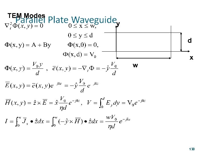
TEM Modes y d x w 138
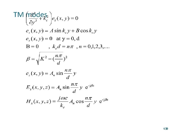
139
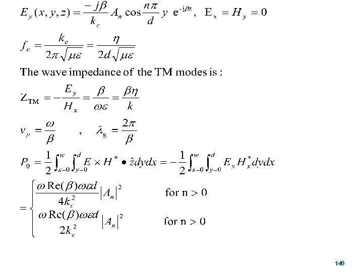
140
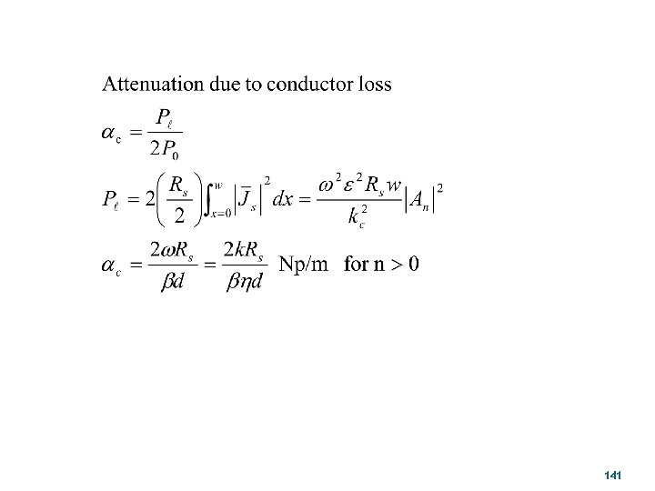
141
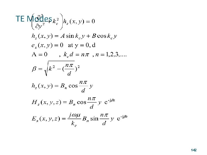
142

143
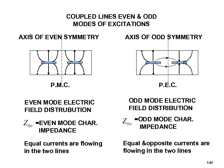
COUPLED LINES EVEN & ODD MODES OF EXCITATIONS AXIS OF EVEN SYMMETRY P. M. C. EVEN MODE ELECTRIC FIELD DISTRUBUTION =EVEN MODE CHAR. IMPEDANCE Equal currents are flowing in the two lines AXIS OF ODD SYMMETRY P. E. C. ODD MODE ELECTRIC FIELD DISTRIBUTION =ODD MODE CHAR. IMPEDANCE Equal &opposite currents are flowing in the two lines 144
007494dc963e7556e9b20f49793a546a.ppt