06c12b09b7deacdcadfdce842d895316.ppt
- Количество слайдов: 122


DREAM IDEA PLAN IMPLEMENTATION
 & Semnan University Dr. Kourosh Kiani")
Present to: Amirkabir University of Technology (Tehran Polytechnic) & Semnan University Dr. Kourosh Kiani 2 Email: kkiani 2004@yahoo. com Email: Kourosh. kiani@aut. ac. ir Web: aut. ac. com
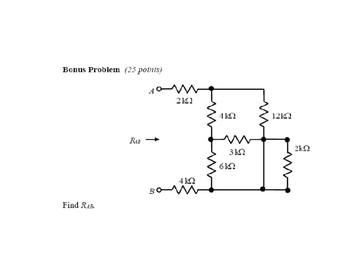
 R 2 a + _ R 1 c d b R 3 R")
i(t) R 2 a + _ R 1 c d b R 3 R 4 v(t) + + _
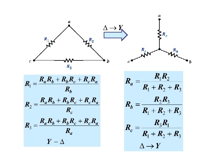

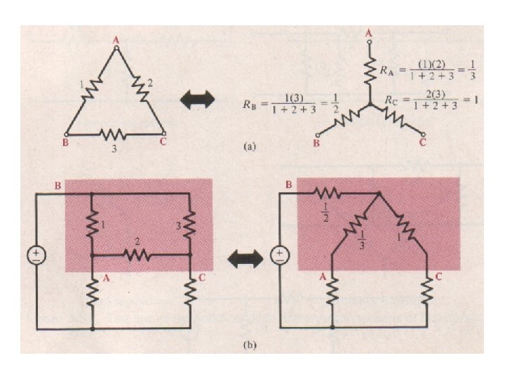
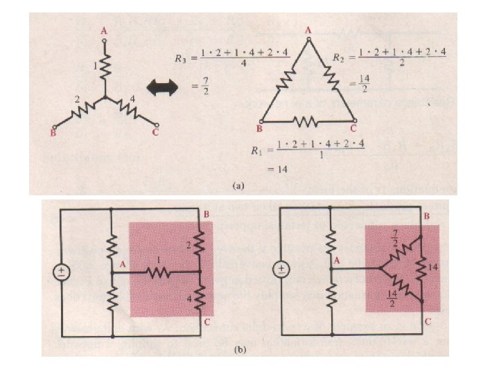
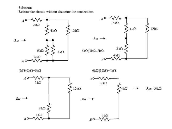
THIS CIRCUIT HAS NO RESISTOR IN SERIES OR PARALLEL IF INSTEAD OF THIS WE COULD HAVE THIS THEN THE CIRCUIT WOULD BECOME LIKE THIS AND BE AMENABLE TO SERIES PARALLEL TRANSFORMATIONS


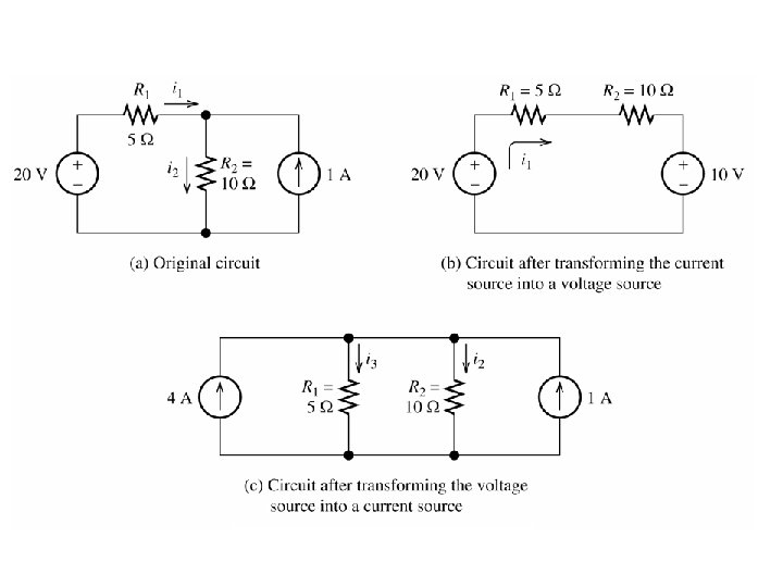
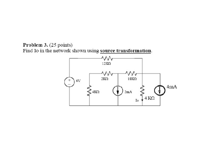
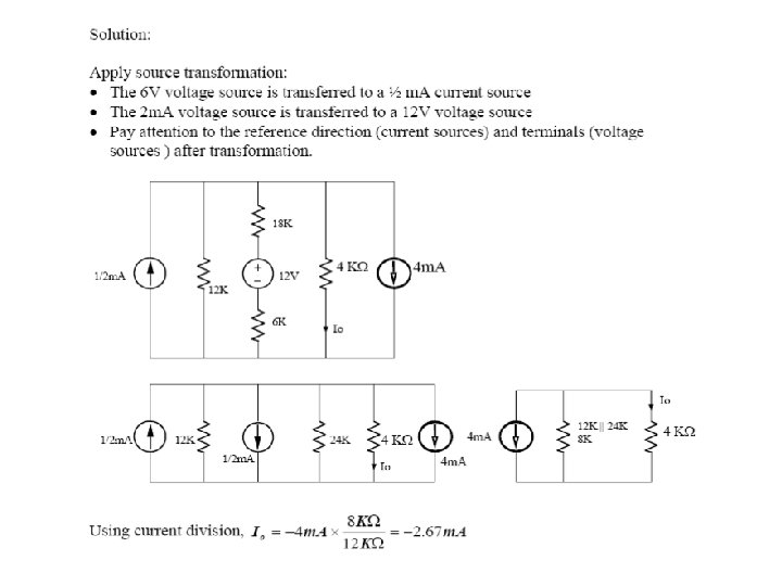
Source Transformations

Maximum Power Transfer The load resistance that absorbs the maximum power from a two-terminal circuit is equal to the Thévenin resistance.

MAXIMUM POWER TRANSFER For every choice of RL we have a different power. How do we find the maximum value? Consider PL as a function of RL and find the maximum of such function 3 Set the derivative to zero to find extreme points. For this case we need to set to zero the numerator The maximum power transfer theorem The value of the maximum The load that maximizes the power transfer for a circuit is power that can be equal to the Thevenin equivalent resistance of the circuit. transferred is

Why Nodal or Loop Analysis? • The analysis techniques (voltage divider, equivalent resistance, etc. ) provide an intuitive approach to analyzing circuits. • They cannot analyze all circuits. • They cannot be easily automated by a computer.

Node and Loop Analysis • Node analysis and loop analysis are both circuit analysis methods which are systematic and apply to most circuits. • Analysis of circuits using node or loop analysis requires solutions of systems of linear equations. • These equations can usually be written by inspection of the circuit.

Node and Loop Analysis • Nodal analysis was developed by applying KCL at each non-reference node. • Loop analysis is developed by applying KVL around loops in the circuit. • Loop (mesh) analysis results in a system of linear equations which must be solved for unknown currents.

Nodal Analysis 1. Choose a reference node. 2. Assign node voltages to the other nodes. 3. Apply KCL to each node other than the reference-express currents in terms of node voltages. 4. Solve the resulting system of linear equations.

Reference Node 500 W + I 1 500 W V 1 k. W 500 W - The reference node is called the ground node. I 2
 1. Choose a reference node. 2. Assign node voltages to the")
Nodal Analysis (cont’d) 1. Choose a reference node. 2. Assign node voltages to the other nodes. 3. Apply KCL to each node other than the reference-express currents in terms of node voltages. 4. Solve the resulting system of linear equations.

Node Voltages V 1 500 W 1 I 1 V 2 500 W V 3 3 1 k. W 500 W I 2 V 1, V 2, and V 3 are unknowns for which we solve using KCL.
 1. Choose a reference node. 2. Assign node voltages to the")
Nodal Analysis (cont’d) 1. Choose a reference node. 2. Assign node voltages to the other nodes. 3. Apply KCL to each node other than the reference-express currents in terms of node voltages. 4. Solve the resulting system of linear equations.

Currents and Node Voltages V 1 500 W V 2 V 1 500 W

KCL at Node 1 KCL: Algebra sum of current leaving the node is 0. V 1 I 1 500 W V 2

KCL at Node 2 V 1 500 W V 2 500 W 1 k. W V 3

KCL at Node 3 V 2 500 W V 3 500 W I 2
 1. Choose a reference node. 2. Assign node voltages to the")
Nodal Analysis (cont’d) 1. Choose a reference node. 2. Assign node voltages to the other nodes. 3. Apply KCL to each node other than the reference-express currents in terms of node voltages. 4. Solve the resulting system of linear equations.

System of Equations • Node 1: • Node 2:

System of Equations • Node 3:

Matrix Notation • The three equations can be combined into a single matrix/vector equation. V 1 500 W 1 I 1 V 2 500 W V 3 3 1 k. W 500 W I 2

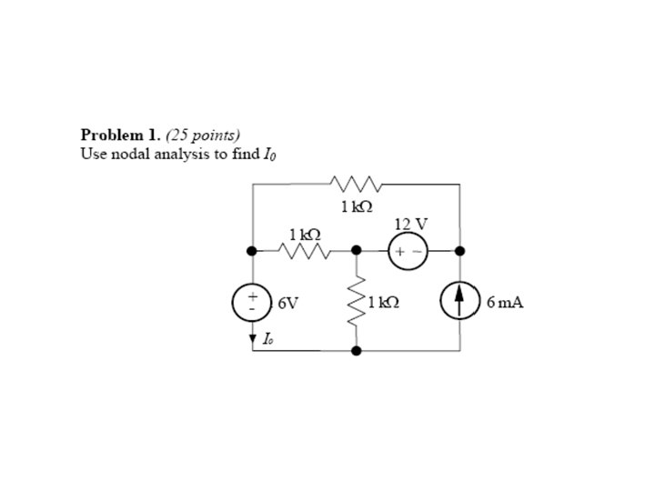
Typical circuit for nodal analysis

i= vhigher - vlower R So at node 1 and node 2, we can get the following equations. I 1 = I 2 + i 1 + i 2 I 2 + i 2 = i 3 I 1 = I 2 + v 1 R 1 v 1 - v 2 R 2 + v 1 - v 2 = v 2 R 3

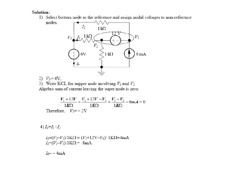
Typical circuit for nodal analysis NUMERICAL MODEL THE NODE EQUATIONS USE GAUSSIAN ELIMINATION THE MODEL REPLACE VALUES AND SWITCH NOTATION TO UPPER CASE

Rearranging terms. . . COULD WRITE EQUATIONS BY INSPECTION

USING KCL BY “INSPECTION”

What if there are dependent sources? Example: Ib 5 m. A 50 W 1 k. W 100 Ib 2 k. W + Vo -

Reference Node Ib 5 m. A 50 W 1 k. W 100 Ib 2 k. W + Vo -

Assign Node Voltages V 1 Ib 1 5 m. A 50 W 1 k. W 100 Ib V 2 2 2 k. W + Vo -

KCL @ Node 1 V 1 Ib 1 5 m. A 50 W 1 k. W 100 Ib V 2 2 2 k. W + Vo -

KCL @ Node 2 V 1 Ib 1 5 m. A 50 W 1 k. W 100 Ib V 2 2 2 k. W + Vo -

The Dependent Source • We must express Ib in terms of the node voltages: • Equation from Node 2 becomes

System of Equations • Node 1: • Node 2:

Matrix Formulation Matrix is not symmetric due to the dependent source.

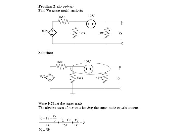
What if there are voltage sources? 0. 7 V 1 + Node 2: Node 3: Ib V 2 V 1 1 k. W 2 + - V 3 V 4 3 4 50 W 100 Ib 3 k. W + Vo 2 k. W - Difficulty: We do not know Ib the current through the voltage source? Independent Voltage Source: V 2 -V 3=0. 7 V Equations: KCL at node 2, KCL at node 3 and V 2 -V 3=0. 7 V Unknowns: Ib, V 2, V 3

0. 7 V 1 Ib V 2 V 1 + - + 1 k. W - V 3 50 W 100 Ib 3 k. W V 4 4 + Vo 2 k. W -

KCL @ the Supernode 0. 7 V 1 Ib V 2 V 1 + - + 1 k. W - V 3 50 W 100 Ib 3 k. W V 4 4 + Vo 2 k. W -

Example Nodal Matrix 0 Symmetric Diagonally Dominant

Assigning Mesh Currents 1 k. W V 1 1 k. W + - I 1 A MESH CURRENT IS the CURRENT ASSOCIATED TO A MESH. I 1, I 2 ARE MESH CURRENTS FOR EVERY CIRCUIT THERE IS A MINIMUM NUMBER OF LOOP CURRENTS THAT ARE NECESSARY TO COMPUTE EVERY CURRENT IN THE CIRCUIT. SUCH A COLLECTION IS CALLED A MINIMAL SET (OF LOOP CURRENTS). + I 2 - V 2 THE DIRECTION OF THE LOOP CURRENTS IS SIGNIFICANT FOR A GIVEN CIRCUIT LET B NUMBER OF BRANCHES N NUMBER OF NODES THE MINIMUM REQUIRED NUMBER OF LOOP CURRENTS IS MESH CURRENTS ARE ALWAYS INDEPENDENT

AN EXAMPLE CLAIM: IN A CIRCUIT, THE CURRENT THROUGH ANY COMPONENT CAN BE EXPRESSED IN TERMS OF THE LOOP CURRENTS TWO LOOP CURRENTS ARE REQUIRED. THE CURRENTS SHOWN ARE MESH CURRENTS. HENCE THEY ARE INDEPENDENT AND FORM A MINIMAL SET
. 2. Assign a current to each")
Steps of Mesh Analysis 1. Identify mesh (loops). 2. Assign a current to each mesh. 3. Apply KVL around each loop to get an equation in terms of the loop currents. 4. Solve the resulting system of linear equations.

Identifying the Meshes 1 k. W V 1 + – 1 k. W Mesh 1 1 k. W Mesh 2 + – V 2
. 2. Assign a current to each")
Steps of Mesh Analysis 1. Identify mesh (loops). 2. Assign a current to each mesh. 3. Apply KVL around each loop to get an equation in terms of the loop currents. 4. Solve the resulting system of linear equations.

Assign a current to each mesh. 1 k. W V 1 + – 1 k. W I 1 I 2 + – V 2
. 2. Assign a current to each")
Steps of Mesh Analysis 1. Identify mesh (loops). 2. Assign a current to each mesh. 3. Apply KVL around each loop to get an equation in terms of the loop currents. 4. Solve the resulting system of linear equations.

Apply KVL around each loop to get an equation in terms of the loop currents. + VR R – I 1 V R = I 1 R + R VR I 2 – I 1 VR = (I 1 - I 2 ) R

KVL Around Mesh 1 1 k. W V 1 + – 1 k. W I 1 I 2 + – V 2 -V 1 + I 1 1 k. W + (I 1 - I 2) 1 k. W = 0 I 1 1 k. W + (I 1 - I 2) 1 k. W = V 1

KVL Around Mesh 2 1 k. W V 1 + – 1 k. W I 1 I 2 + – V 2 (I 2 - I 1) 1 k. W + I 2 1 k. W + V 2 = 0 (I 2 - I 1) 1 k. W + I 2 1 k. W = -V 2
. 2. Assign a current to each")
Steps of Mesh Analysis 1. Identify mesh (loops). 2. Assign a current to each mesh. 3. Apply KVL around each loop to get an equation in terms of the loop currents. 4. Solve the resulting system of linear equations.

Matrix Notation The two equations can be combined • into a single matrix/vector equation.

Solving the Equations Let: V 1 = 7 V and V 2 = 4 V Results: I 1 = 3. 33 m. A I 2 = -0. 33 m. A Finally Vout = (I 1 - I 2) 1 k. W = 3. 66 V

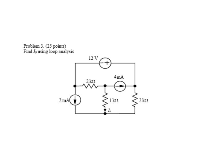
Another Example 2 k. W 2 m. A 12 V + – 1 k. W 2 k. W I 0 4 m. A

1. Identify Meshes 2 k. W 2 m. A Mesh 3 1 k. W 12 V + – Mesh 1 2 k. W Mesh 2 I 0 4 m. A

2. Assign Mesh Currents 2 k. W 2 m. A 12 V + – I 1 I 3 1 k. W 2 k. W I 0 I 2 4 m. A

Current Sources • The current sources in this circuit will have whatever voltage is necessary to make the current correct. • We can’t use KVL around the loop because we don’t know the voltage. • What to do?

Current Sources • The 4 m. A current source sets I 2: I 2 = -4 m. A • The 2 m. A current source sets a constraint on I 1 and I 3: I 1 - I 3 = 2 m. A • We have two equations and three unknowns. Where is the third equation?

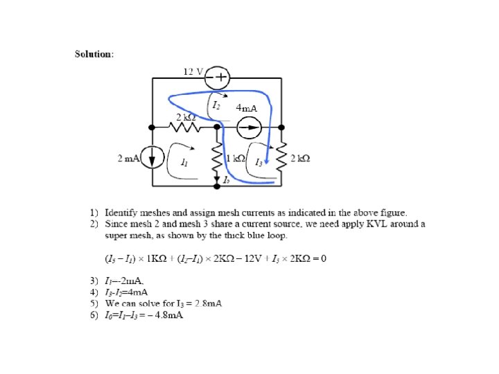
2 k. W The Supermesh surrounds this source! 12 V 2 m. A + – I 3 2 k. W I 2 I 1 I 0 1 k. W The Supermesh does not include this source! 4 m. A

KVL Around the Supermesh -12 V + I 3 2 k. W + (I 3 - I 2)1 k. W + (I 1 - I 2)2 k. W = 0 I 3 2 k. W + (I 3 - I 2)1 k. W + (I 1 - I 2)2 k. W = 12 V

Matrix Notation • The three equations can be combined into a single matrix/vector equation.

Solve Using MATLAB >> A = [0 1 0; 1 0 -1; 2 e 3 -1 e 3 -2 e 3+1 e 3]; >> v = [-4 e-3; 2 e-3; 12]; >> i = inv(A)*v i = 0. 0012 -0. 0040 -0. 0008

Solution I 1 = 1. 2 m. A I 2 = -4 m. A I 3 = -0. 8 m. A I 0 = I 1 - I 2 = 5. 2 m. A

A circuit with two meshes

- V 1 + R 1 i 1 + R 3 (i 1 - i 2 ) = 0 R 2 i 2 + V 2 + R 3 (i 2 - i 1 ) = 0 or ( R 1 + R 3 )i 1 - R 3 i 2 = V 1 - R 3 i 1 + ( R 2 + R 3 )i 2 = -V 2 In matrix form: æ R 1 + R 3 ç ç -R è 3 - R 3 öæ i 1 ö æ V 1 ö ç =ç R 2 + R 3 ø ç i 2 ø ç - V 2 ø è è

A circuit with three meshes For mesh 1, we have For mesh 2, we obtain For mesh 3, we have

A circuit with four meshes

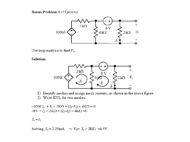
DEPENDENT CURRENT SOURCES NOT SHARED BY MESHES WE ARE ASKED FOR Vo. WE ONLY NEED TO SOLVE FOR I 3 REPLACE AND REARRANGE We treat the dependent source as a conventional source Equations for meshes with current sources Then KVL on the remaining loop(s) And express the controlling variable, Vx, in terms of loop currents

DRAW MESH CURRENTS REPLACE AND REARRANGE WRITE MESH EQUATIONS. SOLVE FOR I 2 CONTROLLING VARIABLE IN TERMS OF LOOP CURRENTS

Mesh Currents in Circuits Containing Current Sources A common mistake made by beginning students is to assume that the voltages across current sources are zero. In Figure we have:

Combine meshes 1 and 2 into a supermesh. In other words, we write a KVL equation around the periphery of meshes 1 and 2 combined. Mesh 3:

Nodal Versus Mesh Analysis • Both provide a systematic way of analyzing a complex network. • When is the nodal method preferred to the mesh method? 1. A circuit with fewer nodes than meshes is better analyzed using nodal analysis, while a circuit with fewer meshes than nodes is better analyzed using mesh analysis. 2. Based on the information required. Node voltages required----nodal analysis Branch or mesh currents required-------mesh analysis

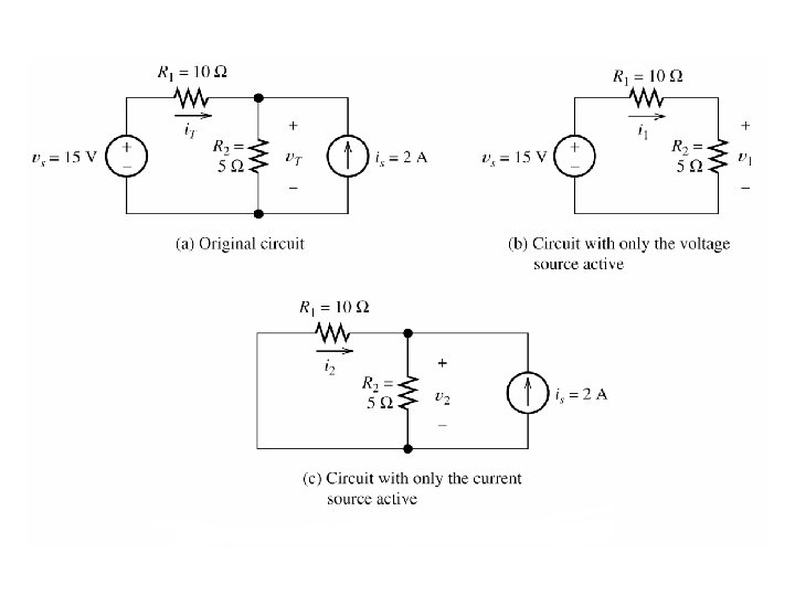
Superposition A linear circuit is one constructed only of linear elements (linear resistors, and linear capacitors and inductors, linear dependent sources) and independent sources. Linear means I-V charcteristic of elements/sources are straight lines when plotted Principle of Superposition: In any linear circuit containing multiple • independent sources, the current or voltage at any point in the network may be calculated as the algebraic sum of the individual contributions of each source acting alone.

Superposition Procedure: 1. Determine contribution due to one independent source • Set all other sources to 0: Replace independent voltage source by short circuit, independent current source by open circuit 2. Repeat for each independent source 3. Sum individual contributions to obtain desired voltage or current

Example 2 k. W 4 m. A 12 V - 2 m. A 1 k. W I 0 + 2 k. W

2 m. A Source 2 k. W 2 m. A 1 k. W I’ 0 = -4/3 m. A 2 k. W

4 m. A Source 2 k. W 4 m. A 1 k. W I’’ 0 = 0 2 k. W

12 V Source 12 V 2 k. W 1 k. W I’’’ 0 = -4 m. A + 2 k. W
 2 k. W 4 m. A 12 V - 2 m. A")
example (cont’d) 2 k. W 4 m. A 12 V - 2 m. A + 1 k. W I 0 = I’ 0 +I’’ 0+ I’’’ 0 = -16/3 m. A 2 k. W
 and resistors can be")
THEVENIN’S THEOREM • Any circuit with sources (dependent and/or independent) and resistors can be replaced by an equivalent circuit containing a single voltage source and a single resistor • Thevenin’s theorem implies that we can replace arbitrarily complicated networks with simple networks for purposes of analysis

TT: Independent Sources RTh Voc Circuit with independent sources + - Thevenin equivalent circuit

TT: No Independent Sources RTh Circuit without independent sources Thevenin equivalent circuit

THEVENIN APPROACH For ANY circuit in Part B This is the Thevenin equivalent circuit for the circuit in Part A The voltage source is called the THEVENIN EQUIVALENT SOURCE PART A MUST BEHAVE LIKE THIS CIRCUIT The resistance is called the THEVENIN EQUIVALENT RESISTANCE

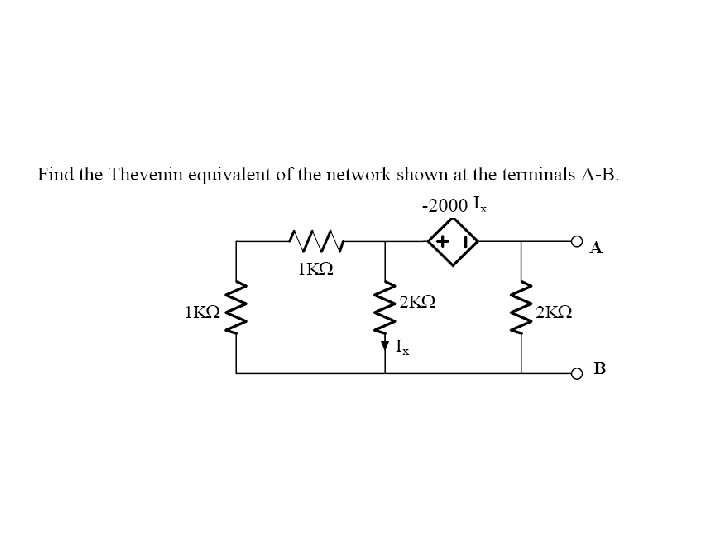
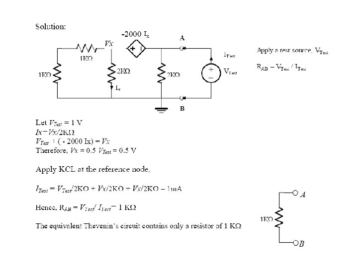
Finding the Thevenin Equivalent • Circuits with independent sources, w/o dependent sources – Compute the open circuit voltage, this is Voc – Compute the Thevenin resistance (set the sources to zero – short circuit the voltage sources, open circuit the current sources), and find the equivalent resistance, this is RTh • Circuits with independent and dependent sources: – Compute the open circuit voltage – Compute the short circuit current – The ratio of the two is RTh • Circuits with dependent sources only – Voc is simply 0 – RTh is found by applying an independent voltage source (V volts) to the terminals and finding voltage/current ratio

NORTON’S THEOREM • Very similar to Thevenin’s theorem • It simply states that any circuit with sources (dependent and/or independent) and resistors can be replaced by an equivalent circuit containing a single current source and a single resistor

Norton Approach Norton

Norton Equivalent: Independent Sources Isc Circuit with one or more independent sources RTh Norton equivalent circuit

No Independent Sources RTh Circuit without independent sources Norton equivalent circuit

Finding the Norton Equivalent • Circuits with independent sources, w/o dependent sources – Compute the short circuit current, this is Isc – Compute the Thevenin resistance (set the sources to zero – short circuit the voltage sources, open circuit the current sources), and find the equivalent resistance, this is RTh • Circuits with both independent and dependent sources – Find Voc and Isc – Compute RTh= Voc/ Isc • Circuits w/o independent sources – Apply a test voltage (current) source – Find resulting current (voltage) – Compute RTh

Questions? Discussion? Suggestions ?

06c12b09b7deacdcadfdce842d895316.ppt