Development of Vibratory Gyro and Accelerometer based on


Development of Vibratory Gyro and Accelerometer based on single sensor Diploma project Student Demchenko Evgen Institute of Aerospace Control systems Department of Aircraft Control System
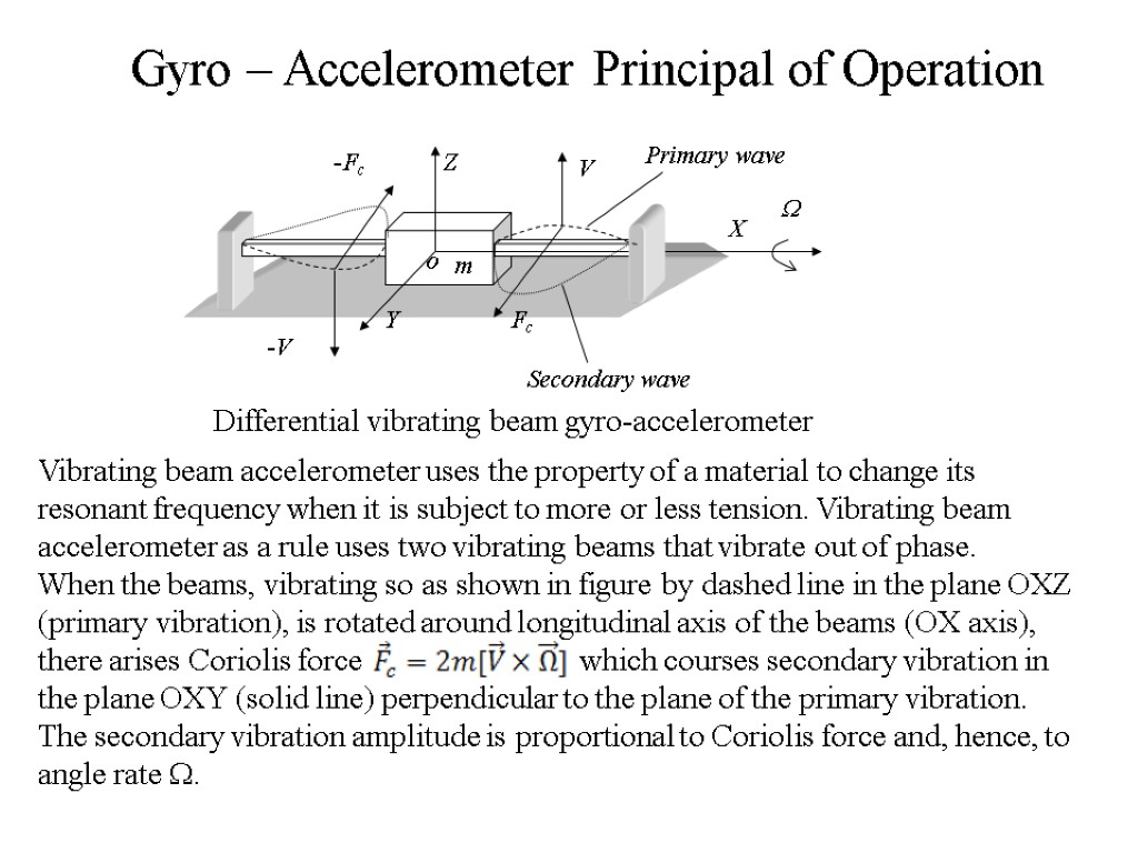
Gyro – Accelerometer Principal of Operation Vibrating beam accelerometer uses the property of a material to change its resonant frequency when it is subject to more or less tension. Vibrating beam accelerometer as a rule uses two vibrating beams that vibrate out of phase. When the beams, vibrating so as shown in figure by dashed line in the plane OXZ (primary vibration), is rotated around longitudinal axis of the beams (OX axis), there arises Coriolis force which courses secondary vibration in the plane OXY (solid line) perpendicular to the plane of the primary vibration. The secondary vibration amplitude is proportional to Coriolis force and, hence, to angle rate .
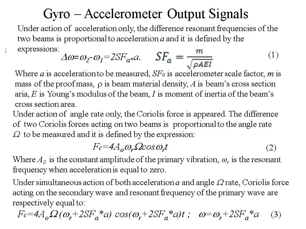
Gyro – Accelerometer Output Signals Under simultaneous action of both acceleration a and angle rate, Coriolis force acting on the secondary wave and resonant frequency of the primary wave are respectively equal to: Fc=4Ao (r+2SFa*a) cos(r+2SFa*a)t ; =r+2SFa*a ; Under action of acceleration only, the difference resonant frequencies of the two beams is proportional to acceleration a and it is defined by the expressions: =2-1=2SFa*a. Where a is acceleration to be measured, SFa is accelerometer scale factor, m is mass of the proof mass, is beam material density, A is beam’s cross section aria, E is Young’s modulus of the beam, I is moment of inertia of the beam’s cross section area. Under action of angle rate only, the Coriolis force is appeared. The difference of two Coriolis forces acting on two beams is proportional to the angle rate to be measured and it is defined by the expression: Fc=4Aorcosrt Where A0 is the constant amplitude of the primary vibration, r is the resonant frequency when acceleration is equal to zero. (1) (2) (3)
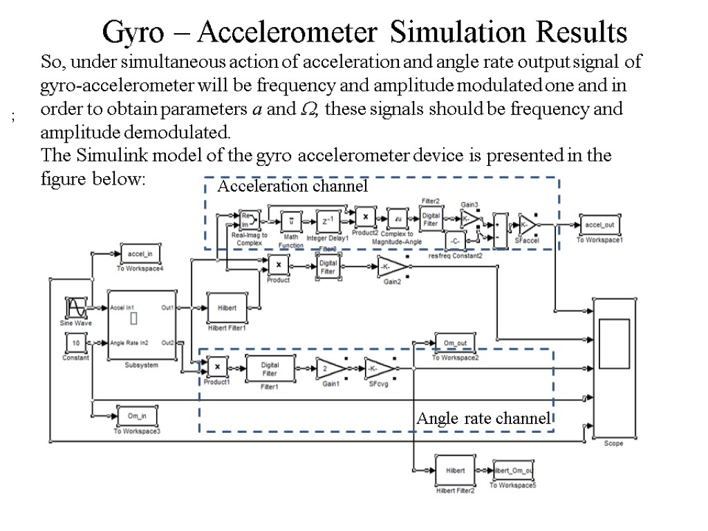
Gyro – Accelerometer Simulation Results ; So, under simultaneous action of acceleration and angle rate output signal of gyro-accelerometer will be frequency and amplitude modulated one and in order to obtain parameters a and , these signals should be frequency and amplitude demodulated. The Simulink model of the gyro accelerometer device is presented in the figure below: Acceleration channel Angle rate channel
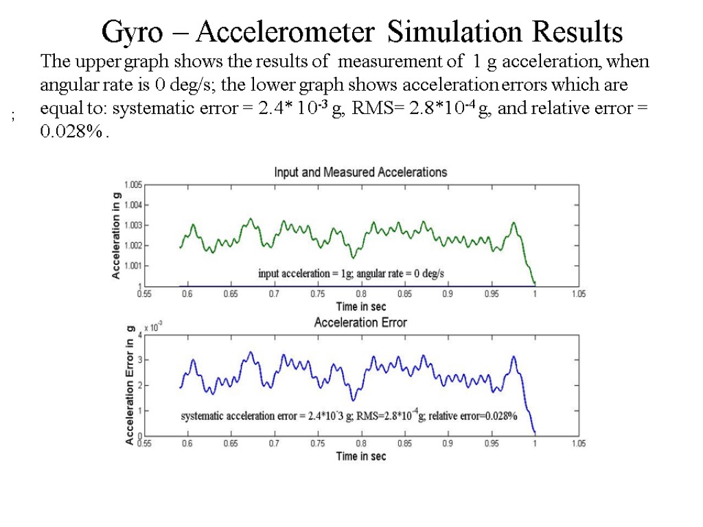
Gyro – Accelerometer Simulation Results ; The upper graph shows the results of measurement of 1 g acceleration, when angular rate is 0 deg/s; the lower graph shows acceleration errors which are equal to: systematic error = 2.4* 10-3 g, RMS= 2.8*10-4 g, and relative error = 0.028% .
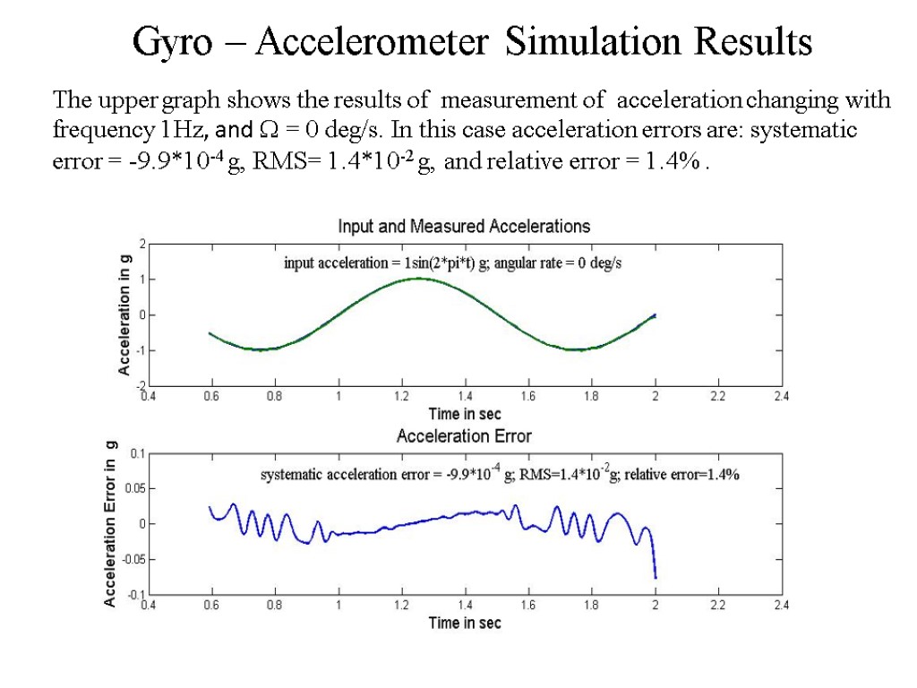
Gyro – Accelerometer Simulation Results The upper graph shows the results of measurement of acceleration changing with frequency 1Hz, and = 0 deg/s. In this case acceleration errors are: systematic error = -9.9*10-4 g, RMS= 1.4*10-2 g, and relative error = 1.4% .
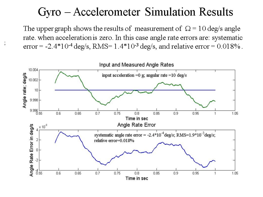
Gyro – Accelerometer Simulation Results ; The upper graph shows the results of measurement of = 10 deg/s angle rate. when acceleration is zero. In this case angle rate errors are: systematic error = -2.4*10-4 deg/s, RMS= 1.4*10-3 deg/s, and relative error = 0.018% .
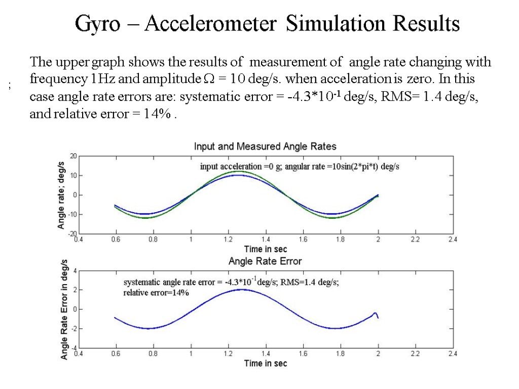
Gyro – Accelerometer Simulation Results ; The upper graph shows the results of measurement of angle rate changing with frequency 1Hz and amplitude = 10 deg/s. when acceleration is zero. In this case angle rate errors are: systematic error = -4.3*10-1 deg/s, RMS= 1.4 deg/s, and relative error = 14% .
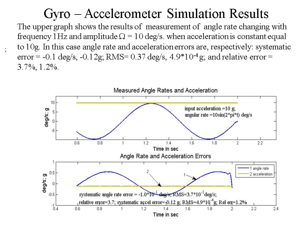
Gyro – Accelerometer Simulation Results ; The upper graph shows the results of measurement of angle rate changing with frequency 1Hz and amplitude = 10 deg/s. when acceleration is constant equal to 10g. In this case angle rate and acceleration errors are, respectively: systematic error = -0.1 deg/s, -0.12g; RMS= 0.37 deg/s, 4.9*10-4 g; and relative error = 3.7%, 1.2%.
Conclusion Single sensor Gyro-Accelerometer can be realized on the basis of vibrating inertial technology. Amplitude demodulation method should be improved to increase accuracy of variable angle rate measurement. Increasing of acceleration error at increasing of acceleration frequency change can be connected with accelerometer scale factor nonlinearity. In order to increase accuracy of the gyro-accelerometer it is expedient to stabilize natural frequency of the resonator using feedback control system.
presentation.ppt
- Количество слайдов: 10

