

6803e768d57f106c94e2e0750e869618.ppt
- Количество слайдов: 34
 Design and Development of Intake Systems for HEPP P M V Subbarao Professor Mechanical Engineering Department Conserve the Potential till the Entrance to Turbo-machine …….
 Methodology of HEPP Development • • • Site Survey: Hydrological & geological Survey. Estimation of Potential Regulations & Environmental Concerns Feasible Supply Turbine Selection Costing and Payback.
 River Characterization using Flow Duration Curve
 Storage plant") Classification of Hydro Power Plants • • Runoff river plant (Diversion plant) Storage plant (Impoundment plant) Pumped storage plant Tidal plant
Classification of Hydro Power Plants • • Runoff river plant (Diversion plant) Storage plant (Impoundment plant) Pumped storage plant Tidal plant
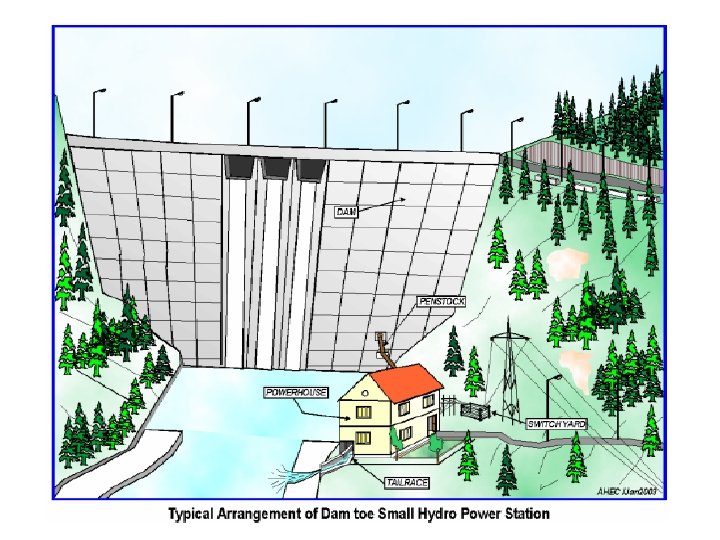
 Typical Arrangement of Natural Ro. R Hydro Plant
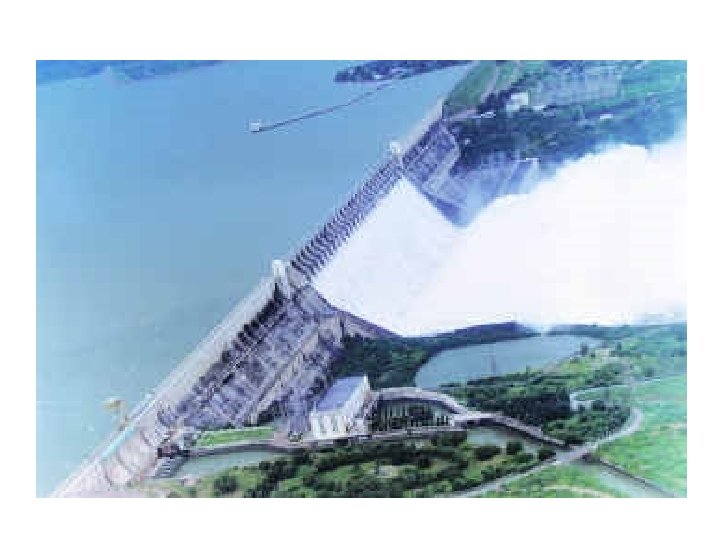
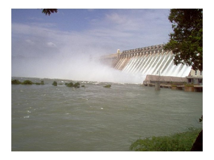
 Creation of Reservoir
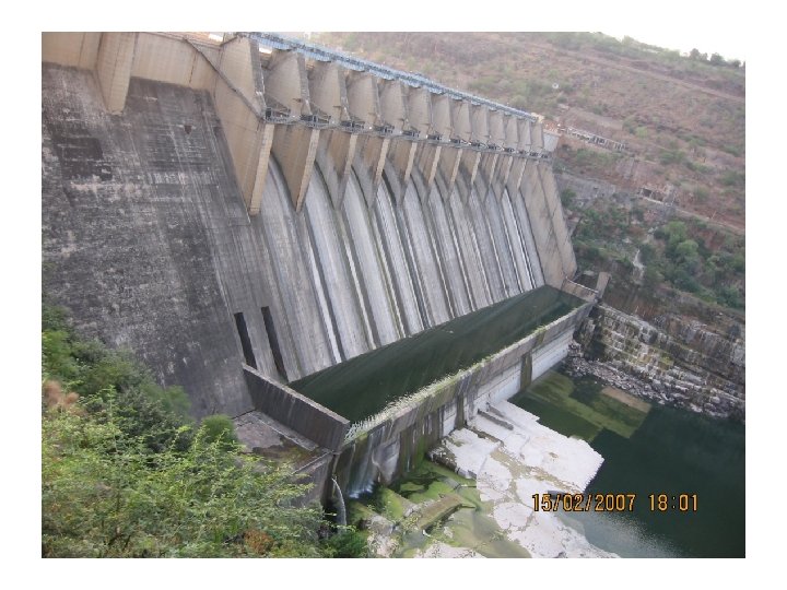
 Creation of Reservoir : Srisailam Height of Dam: 143. 90 m Maximum Depth of Reservoir : 214. 76 m Capacity of the Reservoir: 8, 700 M cum
 Final Acceptable design of Srisailam Project • Techno-economically viable capacity 1670 MW • Head Available : 91. 46 m • No. of units : 7 + 6
 Final Acceptable design of Srisailam Project Srisailam Right Bank Hydro Electric Scheme Unit No 1 2 3 4 5 6 7 Unit No 1 2 3 4 5 6 Capacity (MW) 110 110 110 Date of Commissioning 110 770 Capacity (MW) 150 150 150 900 Make 30 -08 -1982 14 -12 -1982 19 -11 -1983 27 -08 -1984 31 -03 -1986 30 -10 -1986 Turbine BHEL BHEL Generator BHEL BHEL 19 -03 -1987 BHEL Srisailam Left Bank Hydro Electric Schemen Date of Make Commissioning Turbine Generator 26 -04 -2001 Hitachi - Japan Mitshubushi - Japan 12 -11 -2001 Hitachi - Japan Mitshubushi - Japan 19 -04 -2002 Hitachi - Japan Mitshubushi - Japan 29 -11 -2002 Hitachi - Japan Mitshubushi - Japan 28 -03 -2003 Hitachi - Japan Mitshubushi - Japan 04 -09 -2003 Hitachi - Japan Mitshubushi - Japan
 The Power House
 Global Layout of A Hydro Power Plant
 Structure of Intake Systems Power Tunnel: Diameter: 15000 mm Length= 746 m Slope= 1 in 120 Actual velocity: 5. 563 m/s
 Penstock
 Intake Hydraulic Structures • • These structures include Intakes; Headrace channels; Conveyance tunnels; Penstocks; Surge tanks; Penstock manifolds;
 Principles for the arrangement of the intake structure on the river • With the discharge, each river entrains solid matter in the form of suspended matter or as bed load. • The location of an intake structure must be so chosen that the largest possible portion of the bed load remains in the river and is not taken in the intake canal system. • A satisfactory arrangement of the intake structure does not remove the suspended matter. • To hold off the bed load the natural hydraulic behaviour of the river can be exploited through physical laws.
 Physical Laws of Natural Rivers • Law 1: In straight sections of river or stream, the water flows approximately in the cross-section of the channel, parallel to the banks. • When the bed load transport begins, the bed load is transported accordingly on the bottom of the river. • Law 2: In bends the direction of the bottom flow changes compared with the surface flow. • A spiral flow forms which transports the bed load to the inner side of the river. • On all streams and rivers it can be observed that gravel and sand banks form at the inside bend, i. e. the bed load is diverted from the intake bank.
 Dynamics of Deposits in a river bend
 Strategies to Enhance the life of Turbine
 Intake from Straight River
 Hydraulic Design of Intake Weir Q = discharge over the downstream face in m³/s, c = correction factor for submerged overfall, μ =weir coefficient, b = weir crest width in m, g = acceleration due to gravity = 9. 81 m/s², hü = weir head in m.
 Global Layout of Intake system for HEPP
 Structure of Intake Systems
 Power Tunnels : Constant Pressure & Accelerating Flow
 Power Tunnel Channel Bed Slope
 High Pressure Piping : Penstock
 General Design of Under Ground Power Tunnels
 Pipe Material drawn brass drawn copper commercial steel wrought iron asphalted cast iron galvanized iron cast iron wood stave Absolute Roughness, e micron (unless noted) 1. 5 45 45 120 150 260 0. 2 to 0. 9 mm concrete 0. 3 to 3 mm riveted steel 0. 9 to 9 mm Estimate net Head available at the inlet of turbine casing
 Optimum Diameter of Power Tunnel • With increasing diameter, • the head losses and consequent energy losses in a power tunnel decreases, • While construction cost increases. • The objection of economic analysis is to minimize total annual costs. • Total cost consists of the annual charges from the investment and monetary value of lost energy.
 The energy lost per day • The energy loss during particular day i, due to friction is: • • Energy loss, E Darcy –Weisbach friction factor, f Discharge through tubine system, Q Duration of plant running, ti (h/day)
 Monetary Loss due to Unavailable Energy & Annual Capital Cost Annual Capital cost: CRF : Capital Recovery Factor n= Economic scaling factor Total annual cost, T = ML+C