

3fd7916df318680fb114a75701afec0e.ppt
- Количество слайдов: 89
 CPU: Instruction Sets and Instruction Cycles Chapters 10, 11 and 12, William Stallings Computer Organization and Architecture 7 th Edition
 What is an Instruction Set? • The complete collection of instructions that are understood by a CPU • Machine language: binary representation of operations and (addresses of) arguments • Assembly language: mnemonic representation for humans, e. g. , OP A, B, C (meaning A <- OP(B, C))
 – Do this: ADD, SUB, MPY,") Elements of an Instruction • Operation code (opcode) – Do this: ADD, SUB, MPY, DIV, LOAD, STOR • Source operand reference – To this: (address of) argument of op, e. g. register, memory location • Result operand reference – Put the result here (as above) • Next instruction reference (often implicit) – When you have done that, do this: BR
Elements of an Instruction • Operation code (opcode) – Do this: ADD, SUB, MPY, DIV, LOAD, STOR • Source operand reference – To this: (address of) argument of op, e. g. register, memory location • Result operand reference – Put the result here (as above) • Next instruction reference (often implicit) – When you have done that, do this: BR
 • Operation repertoire – How many ops? – What can they") Design Decisions (1) • Operation repertoire – How many ops? – What can they do? – How complex are they? • Data types (length of words, integer representation) • Instruction formats – Length of op code field – Length and number of addresses (e. g. , implicit addressing)
Design Decisions (1) • Operation repertoire – How many ops? – What can they do? – How complex are they? • Data types (length of words, integer representation) • Instruction formats – Length of op code field – Length and number of addresses (e. g. , implicit addressing)
 • Registers – Number of CPU registers available – Which operations") Design Decisions (2) • Registers – Number of CPU registers available – Which operations can be performed on which registers? General purpose and specific registers • Addressing modes (see later) • RISC v CISC
Design Decisions (2) • Registers – Number of CPU registers available – Which operations can be performed on which registers? General purpose and specific registers • Addressing modes (see later) • RISC v CISC
 Instruction Types • Data transfer: registers, main memory, stack or I/O • Data processing: arithmetic, logical • Control: systems control, transfer of control
 Data Transfer • Store, load, exchange, move, clear, set, push, pop • Specifies: source and destination (memory, register, stack), amount of data • May be different instructions for different (size, location) movements, e. g. , IBM S/390: L (32 bit word, R<-M), LH (halfword, R<-M), LR (word, R<-R), plus floating-point registers LER, LE, LDR, LD Or one instruction and different addresses, e. g. VAX: MOV
 Input/Output • May be specific instructions, e. g. INPUT, OUTPUT • May be done using data movement instructions (memory mapped I/O) • May be done by a separate controller (DMA): Start I/O, Test I/O
 Arithmetic • Add, Subtract, Multiply, Divide for signed integer (+ floating point and packed decimal) – may involve data movement • May include – Absolute (|a|) – Increment (a++) – Decrement (a--) – Negate (-a)
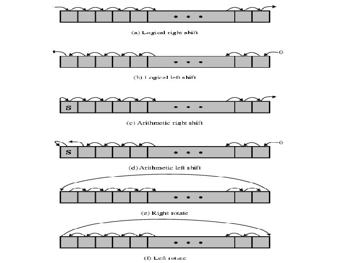
 Logical • Bitwise operations: AND, OR, NOT, XOR, TEST, CMP, SET • Shifting and rotating functions, e. g. – logical right shift for unpacking: send 8 -bit character from 16 -bit word – arithmetic right shift: division and truncation for odd numbers – arithmetic left shift: multiplication without overflow
 Systems Control • Privileged instructions: accessing control registers or process table • CPU needs to be in specific state – Ring 0 on 80386+ – Kernel mode • For operating systems use
 Transfer of Control • Skip, e. g. , increment and skip if zero: ISZ Reg 1, cf. jumping out from loop • Branch instructions: BRZ X (branch to X if result is zero), BRP X (positive), BRN X (negative), BRE X, R 1, R 2 (equal) • Procedure (economy and modularity): call and return
 Branch Instruction
 Nested Procedure Calls
 Use of Stack: Saving the return address for reentrant procedures
 Types of Operand • Addresses: immediate, direct, indirect, stack • Numbers: integer or fixed point (binary, twos complement), floating point (sign, significand, exponent), (packed) decimal (246 = 0000 0010 0100 0110) • Characters: ASCII (128 printable and control characters + bit for error detection) • Logical Data: bits or flags, e. g. , Boolean 0 and 1
 Pentium Data Types • Addressing is by 8 bit unit • General data types: 8 bit Byte, 16 bit word, 32 bit double word, 64 bit quad word • Integer: signed binary using twos complement representation • (Un)packed decimal • Near pointer: offset in segment • Bit field • Strings • Floating point
 Instruction Formats • • Layout of bits in an instruction Includes opcode Includes (implicit or explicit) operand(s) Usually more than one instruction format in an instruction set
") Simple Instruction Format (using two addresses)
Simple Instruction Format (using two addresses)
 Instruction Length • Affected by and affects: – Memory size – Memory organization - addressing – Bus structure, e. g. , width – CPU complexity – CPU speed • Trade off between powerful instruction repertoire and saving space
 Allocation of Bits • Number of addressing modes: implicit or additional bits specifying it • Number of operands • Register (faster, limited size and number, 32) versus memory • Number of register sets, e. g. , data and address (shorter addresses) • Address range • Address granularity (e. g. , by byte)
 instructions – More") Number of Addresses • More addresses – More complex (powerful? ) instructions – More registers - inter-register operations are quicker – Less instructions per program • Fewer addresses – Less complex (powerful? ) instructions – More instructions per program, e. g. data movement – Faster fetch/execution of instructions • Example: Y=(A-B): [(C+(Dx. E)]
Number of Addresses • More addresses – More complex (powerful? ) instructions – More registers - inter-register operations are quicker – Less instructions per program • Fewer addresses – Less complex (powerful? ) instructions – More instructions per program, e. g. data movement – Faster fetch/execution of instructions • Example: Y=(A-B): [(C+(Dx. E)]
 3 addresses Operation Result, Operand 1, Operand 2 – Not common – Needs very long words to hold everything SUB Y, A, B Y <- A-B MPY T, D, E T <- Dx. E ADD T, T, C T <- T+C DIV Y, Y, T Y <- Y: T
 2 addresses One address doubles as operand result – Reduces length of instruction – Requires some extra work: temporary storage MOVE Y, A Y <- A SUB Y, B Y <- Y-B MOVE T, D T <- D MPY T, E T <- Tx. E ADD T, C T <- T+C DIV Y, T Y <- Y: T
 LOAD D AC <-") 1 address Implicit second address, usually a register (accumulator, AC) LOAD D AC <- D MPY E AC <- ACx. E ADD C AC <- AC+C STOR Y Y <- AC LOAD A AC <- A SUB B AC <- AC-B DIV Y AC <- AC: Y STOR Y Y <- AC
1 address Implicit second address, usually a register (accumulator, AC) LOAD D AC <- D MPY E AC <- ACx. E ADD C AC <- AC+C STOR Y Y <- AC LOAD A AC <- A SUB B AC <- AC-B DIV Y AC <- AC: Y STOR Y Y <- AC
 addresses All addresses implicit, e. g. ADD – Uses a stack, e.") 0 (zero) addresses All addresses implicit, e. g. ADD – Uses a stack, e. g. pop a, pop b, add –c=a+b
0 (zero) addresses All addresses implicit, e. g. ADD – Uses a stack, e. g. pop a, pop b, add –c=a+b
 Stack") Addressing Modes • • Immediate Direct Indirect Register Indirect Displacement (Indexed) Stack
Addressing Modes • • Immediate Direct Indirect Register Indirect Displacement (Indexed) Stack
 Immediate Addressing • Operand is part of instruction • Operand = address field • e. g. , ADD 5 or ADD #5 – Add 5 to contents of accumulator – 5 is operand • No memory reference to fetch data • Fast • Limited range
 =") Direct Addressing • Address field contains address of operand • Effective address (EA) = address field (A) • e. g. , ADD A – Add contents of cell A to accumulator – Look in memory at address A for operand • Single memory reference to access data • No additional calculations needed to work out effective address • Limited address space (length of address field)
Direct Addressing • Address field contains address of operand • Effective address (EA) = address field (A) • e. g. , ADD A – Add contents of cell A to accumulator – Look in memory at address A for operand • Single memory reference to access data • No additional calculations needed to work out effective address • Limited address space (length of address field)
 Direct Addressing Diagram Instruction Opcode Address A Memory Operand
 • Memory cell pointed to by address field contains the address") Indirect Addressing (1) • Memory cell pointed to by address field contains the address of (pointer to) the operand • EA = (A) – Look in A, find address (A) and look there for operand • E. g. ADD (A) – Add contents of cell pointed to by contents of A to accumulator
Indirect Addressing (1) • Memory cell pointed to by address field contains the address of (pointer to) the operand • EA = (A) – Look in A, find address (A) and look there for operand • E. g. ADD (A) – Add contents of cell pointed to by contents of A to accumulator
 • Large address space • 2 n where n = word") Indirect Addressing (2) • Large address space • 2 n where n = word length • May be nested, multilevel, cascaded – e. g. EA = (((A))) • Multiple memory accesses to find operand • Hence slower
Indirect Addressing (2) • Large address space • 2 n where n = word length • May be nested, multilevel, cascaded – e. g. EA = (((A))) • Multiple memory accesses to find operand • Hence slower
 Indirect Addressing Diagram Instruction Opcode Address A Memory Pointer to operand Operand
 • Operand is held in register named in address field •") Register Addressing (1) • Operand is held in register named in address field • EA = R • Limited number of registers • Very small address field needed – Shorter instructions – Faster instruction fetch
Register Addressing (1) • Operand is held in register named in address field • EA = R • Limited number of registers • Very small address field needed – Shorter instructions – Faster instruction fetch
 • • No memory access Very fast execution Very limited address") Register Addressing (2) • • No memory access Very fast execution Very limited address space Multiple registers helps performance – Requires good assembly programming or compiler writing – see register renaming • cf. direct addressing
Register Addressing (2) • • No memory access Very fast execution Very limited address space Multiple registers helps performance – Requires good assembly programming or compiler writing – see register renaming • cf. direct addressing
 Register Addressing Diagram Instruction Opcode Register Address R Registers Operand
 • Operand is") Register Indirect Addressing • Cf. indirect addressing • EA = (R) • Operand is in memory cell pointed to by contents of register R • Large address space (2 n) • One fewer memory access than indirect addressing
Register Indirect Addressing • Cf. indirect addressing • EA = (R) • Operand is in memory cell pointed to by contents of register R • Large address space (2 n) • One fewer memory access than indirect addressing
 Register Indirect Addressing Diagram Instruction Opcode Register Address R Memory Registers Pointer to Operand
 • Address field hold two values") Displacement Addressing • EA = A + (R) • Address field hold two values – A = base value – R = register that holds displacement – or vice versa • See segmentation
Displacement Addressing • EA = A + (R) • Address field hold two values – A = base value – R = register that holds displacement – or vice versa • See segmentation
 Displacement Addressing Diagram Instruction Opcode Register R Address A Memory Registers Displacement + Operand
 Relative Addressing • • A version of displacement addressing R = Program counter, PC EA = A + (PC) i. e. , get operand from A cells away from current location pointed to by PC • cf. locality of reference & cache usage
 Base-Register Addressing • • A holds displacement R holds pointer to base address R may be explicit or implicit e. g. , segment registers in 80 x 86
 Indexed Addressing • • A = base R = displacement EA = A + R Good for iteration, e. g. , accessing arrays – EA = A + R – R++ • Sometimes automated: autoindexing (signalled by one bit in instruction)
 on top of stack • e. g. –") Stack Addressing • Operand is (implicitly) on top of stack • e. g. – ADD Pop two items from stack and add and push result on top
Stack Addressing • Operand is (implicitly) on top of stack • e. g. – ADD Pop two items from stack and add and push result on top
: – Displacement and indirect") Power. PC Addressing Modes • Load/store architecture (see next slide): – Displacement and indirect indexed – EA = base + displacement/index – with updating base by computed address • Branch address – Absolute – Relative (see loops): (PC) + I – Indirect: from register • Arithmetic – Operands in registers or part of instruction – For floating point: register only
Power. PC Addressing Modes • Load/store architecture (see next slide): – Displacement and indirect indexed – EA = base + displacement/index – with updating base by computed address • Branch address – Absolute – Relative (see loops): (PC) + I – Indirect: from register • Arithmetic – Operands in registers or part of instruction – For floating point: register only
 Power. PC Memory Operand Addressing Modes
 CPU Function • CPU must: – Fetch instructions – Interpret/decode instructions – Fetch data – Process data – Write data
 CPU With Systems Bus
 - registers • Number") Registers • CPU must have some working space (temporary storage) - registers • Number and function vary between processor designs - one of the major design decisions • Top level of memory hierarchy
Registers • CPU must have some working space (temporary storage) - registers • Number and function vary between processor designs - one of the major design decisions • Top level of memory hierarchy
 User Visible Registers • • General Purpose Data Address Condition Codes
 • • • May be true general purpose May be") General Purpose Registers (1) • • • May be true general purpose May be restricted May be used for data or addressing Data: accumulator (AC) Addressing: segment (cf. virtual memory), stack (points to top of stack, cf. implicit addressing)
General Purpose Registers (1) • • • May be true general purpose May be restricted May be used for data or addressing Data: accumulator (AC) Addressing: segment (cf. virtual memory), stack (points to top of stack, cf. implicit addressing)
 • Make them general purpose – Increased flexibility and programmer") General Purpose Registers (2) • Make them general purpose – Increased flexibility and programmer options – Increased instruction size & complexity, addressing • Make them specialized – Smaller (faster) but more instructions – Less flexibility, addresses implicit in opcode
General Purpose Registers (2) • Make them general purpose – Increased flexibility and programmer options – Increased instruction size & complexity, addressing • Make them specialized – Smaller (faster) but more instructions – Less flexibility, addresses implicit in opcode
 How Many GP Registers? • • Between 8 - 32 Less = more memory references More takes up processor real estate See also RISC
 How big? • Large enough to hold full address • Large enough to hold full data types • But often possible to combine two data registers or two address registers by using more complex addressing (e. g. , page and offset)
 • Instruction Register (IR) • Memory") Control & Status Registers • Program Counter (PC) • Instruction Register (IR) • Memory Address Register (MAR) – connects to address bus • Memory Buffer Register (MBR) – connects to data bus, feeds other registers
Control & Status Registers • Program Counter (PC) • Instruction Register (IR) • Memory Address Register (MAR) – connects to address bus • Memory Buffer Register (MBR) – connects to data bus, feeds other registers
 Condition Code Registers – Flags • Sets of individual bits, flags – e. g. , result of last operation was zero • Can be read by programs – e. g. , Jump if zero – simplifies branch taking • Can not (usually) be set by programs
 Program Status Word • A set of bits • Condition Codes: – Sign (of last result) – Zero (last result) – Carry (multiword arithmetic) – Equal (two latest results) – Overflow • Interrupts enabled/disabled • Supervisor/user mode
 Supervisor Mode • • • Intel ring zero Kernel mode Allows privileged instructions to execute Used by operating system Not available to user programs
") Other Registers • May have registers pointing to: – Process control blocks (see OS) – Interrupt Vectors (see OS) • N. B. CPU design and operating system design are closely linked
Other Registers • May have registers pointing to: – Process control blocks (see OS) – Interrupt Vectors (see OS) • N. B. CPU design and operating system design are closely linked
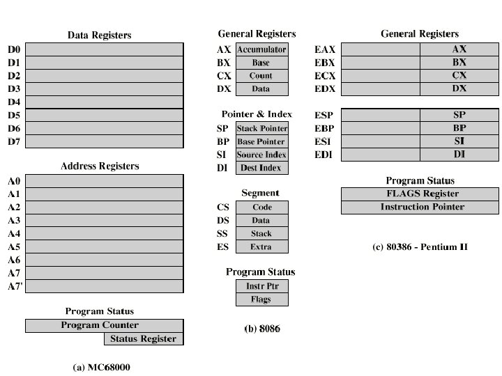
 MC 68000 and Intel registers • Motorola: – Largely general purpose registers – explicit addressing – Data registers also for indexing – A 7 and A 7’ for user and kernel stacks • Intel – Largely specific purpose registers – implicit addressing – Segment, Pointer & Index, Data/General purpose – Pentium II – backward compatibility
 Indirect Cycle • Same address can refer to different arguments (by changing the content of the location the address is pointing to) • Indirect addressing requires more memory accesses to fetch operands • Can be thought of as additional instruction subcycle
 Instruction Cycle State Diagram
 • • • PC contains address of next instruction Address") Data Flow (Instruction Fetch) • • • PC contains address of next instruction Address moved to MAR Address placed on address bus Control unit requests memory read Result placed on data bus, copied to MBR, then to IR • Meanwhile PC incremented by 1
Data Flow (Instruction Fetch) • • • PC contains address of next instruction Address moved to MAR Address placed on address bus Control unit requests memory read Result placed on data bus, copied to MBR, then to IR • Meanwhile PC incremented by 1
") Data Flow (Fetch Diagram)
Data Flow (Fetch Diagram)
 • IR is examined • If indirect addressing, indirect cycle") Data Flow (Data Fetch) • IR is examined • If indirect addressing, indirect cycle is performed – Rightmost n bits of MBR (address part of instruction) transferred to MAR – Control unit requests memory read – Result (address of operand) moved to MBR
Data Flow (Data Fetch) • IR is examined • If indirect addressing, indirect cycle is performed – Rightmost n bits of MBR (address part of instruction) transferred to MAR – Control unit requests memory read – Result (address of operand) moved to MBR
") Data Flow (Indirect Diagram)
Data Flow (Indirect Diagram)
 • May take many forms, depends on instruction being executed •") Data Flow (Execute) • May take many forms, depends on instruction being executed • May include – Memory read/write – Input/Output – Register transfers – ALU operations
Data Flow (Execute) • May take many forms, depends on instruction being executed • May include – Memory read/write – Input/Output – Register transfers – ALU operations
 • Current PC saved to allow resumption after interrupt • Contents") Data Flow (Interrupt) • Current PC saved to allow resumption after interrupt • Contents of PC copied to MBR • Special memory location (e. g. , stack pointer) loaded to MAR • MBR written to memory according to content of MAR • PC loaded with address of interrupt handling routine • Next instruction (first of interrupt handler) can be fetched
Data Flow (Interrupt) • Current PC saved to allow resumption after interrupt • Contents of PC copied to MBR • Special memory location (e. g. , stack pointer) loaded to MAR • MBR written to memory according to content of MAR • PC loaded with address of interrupt handling routine • Next instruction (first of interrupt handler) can be fetched
") Data Flow (Interrupt Diagram)
Data Flow (Interrupt Diagram)
 Prefetch • Fetch involves accessing main memory • Execution of ALU operations do not access main memory • Can fetch next instruction during execution of current instruction, cf. assembly line • Called instruction prefetch
 Improved Performance • But not doubled: – Fetch usually shorter than execution (cf. reading and storing operands) • Prefetch more than one instruction? – Any jump or branch means that prefetched instructions are not the required instructions • Add more stages to improve performance
 1. 2. 3. 4. 5. 6. Fetch instruction Decode instruction Calculate") Pipelining (six stages) 1. 2. 3. 4. 5. 6. Fetch instruction Decode instruction Calculate operands (i. e. , EAs) Fetch operands Execute instructions Write result • Overlap these operations
Pipelining (six stages) 1. 2. 3. 4. 5. 6. Fetch instruction Decode instruction Calculate operands (i. e. , EAs) Fetch operands Execute instructions Write result • Overlap these operations
") Timing Diagram for Instruction Pipeline Operation (assuming independence)
Timing Diagram for Instruction Pipeline Operation (assuming independence)
 The Effect of a Conditional Branch/Interrupt on Instruction Pipeline Operation
 Six Stage Instruction Pipeline
 (ideally)") Speedup Factors with Instruction Pipelining: nk/(n+k-1) (ideally)
Speedup Factors with Instruction Pipelining: nk/(n+k-1) (ideally)
 Dealing with Branches 1. 2. 3. 4. Prefetch Branch Target Loop buffer Branch prediction Delayed branching (see RISC)
 Prefetch Branch Target • Target of branch is prefetched in addition to instructions following branch • Keep target until branch is executed • Used by IBM 360/91
 Loop Buffer • • • Very fast memory Maintained by fetch stage of pipeline Check buffer before fetching from memory Very good for small loops or jumps cf. cache
 Branch Prediction • Predict by Opcode – Some instructions are more likely to result in a jump than others – Can get up to 75% success • Taken/Not taken switch – Based on previous history – Good for loops • Delayed branch – rearrange instructions (see RISC)
") Branch Prediction State Diagram (two bits)
Branch Prediction State Diagram (two bits)
 Branch Prediction Flowchart
 Intel 80486 Pipelining 1. Fetch – – 2. Put in one of two 16 -byte prefetch buffers Fill buffer with new data as soon as old data consumed Average 5 instructions fetched per load (variable size) Independent of other stages to keep buffers full Decode stage 1 – – – 3. Opcode & address-mode info At most first 3 bytes of instruction needed for this Can direct D 2 stage to get rest of instruction Decode stage 2 – – 4. Expand opcode into control signals Computation of complex addressing modes Execute – 5. ALU operations, cache access, register update Writeback – – Update registers & flags Results sent to cache
 Pentium 4 Registers
 EFLAGS Register
 Control Registers
: (non-)maskable • Exceptions (software): processor detected (error) or") Pentium Interrupt Processing • Interrupts (hardware): (non-)maskable • Exceptions (software): processor detected (error) or programmed (exception) • Interrupt vector table – Each interrupt type assigned a number – Index to vector table – 256 * 32 bit interrupt vectors (address of ISR) • 5 priority classes: 1. exception by previous instruction 2. external interrupt, 3. -5. faults from fetching, decoding or executing instruction
Pentium Interrupt Processing • Interrupts (hardware): (non-)maskable • Exceptions (software): processor detected (error) or programmed (exception) • Interrupt vector table – Each interrupt type assigned a number – Index to vector table – 256 * 32 bit interrupt vectors (address of ISR) • 5 priority classes: 1. exception by previous instruction 2. external interrupt, 3. -5. faults from fetching, decoding or executing instruction