

431c3c06cb43523797d6b9a5a940d262.ppt
- Количество слайдов: 70
 CPS 356: Introduction to Computer Networks Lecture 2: Network Architectures Reference: Chapter 1 of [PD] Xiaowei Yang xwy@cs. duke. edu
 Overview • Updated course administrative stuff – Grading policy, office hours, piazza • Design requirements of the original Internet • Concepts of Network Architectures • An Example of how the Internet works
 Updated Grading Policy • Old – Class participation and pop quizzes: 20% – Assignments: 50% • In a group assignment, both students get the same grade for the assignment – Exams: 30% • New – Class participation and pop quizzes: 10% – Assignments: 60% • In a group assignment, both students get the same grade for the assignment – Exams: 30%
 Office hours • Instructor – Fridays: 3 -5 pm • TA – Tuesdays 7 -9 pm
 Discussion Forum • Piazza sign up link – piazza. com/duke/spring 2014/compsci 356
 Overview • Updated course administrative stuff – Grading policy, office hours, piazza • Design requirements of the original Internet • Concepts of Network Architectures • An Example of how the Internet works
 1 st Mission of this course • Understand the concepts and design principles that make the Internet work • Design paradigm – Identify requirements, brainstorm design choices/mechanisms, make design decisions – What requirements make sense to you? • • • Scalable connectivity Cost-effective resource sharing Support for different types of services Manageability … – It remains an open challenge how to incorporate other requirements such as security into the Internet design
 Features of computer networks • Generality • Carry many different types of data • Support an unlimited range of applications
 What’s the Internet? • The Internet is a large-scale general-purpose computer network. – Run more than one applications • The Internet transfers data between computers. • The Internet is a network of networks.
 Design requirements and techniques to meet them 1. 2. 3. 4. Scalable connectivity Cost-effective resource sharing Support for common services Manageability
 1. Scalable Connectivity • A network must provide connectivity among a set of computers – Open vs close: to connect all computers or a subset of them? – Internet is an open network • Scalability: A system is designed to grow to an arbitrary large size is said to scale – How to connect an arbitrary large number of computers on a network?
 Connectivity recursively occurs at different levels Point-to-Point Multiple-Access • Link-level: connect two or more computers via a physical medium • Computers are referred to as nodes • The physical medium is referred to as a link
 Switching • Switching is a mechanism to achieve connectivity • Nodes that are attached to at least two links forward data from one link to another link • They are called switches • Computers outside the cloud are called hosts • A question: switch vs router, what can become a switch?
 • Circuit switching – Sets up a circuit before nodes can communicate – Switches connect circuits on different links • Packet switching – Data are split into blocks of data called packets – Store and forward – Nodes send packets and switches forward them
 Internetworking: Another way to achieve connectivity • An internetwork of networks – Each cloud is a network/a multiple-access link – A node that is connected to two or more networks is commonly called a router • Speaks different protocols than switches – An internet can be viewed as a “cloud. ” We can recursively build larger clouds by connecting smaller ones – Autonomous system (AS)
 Addressing and routing • • Physical connectivity != connectivity Addressing and routing are mechanisms to achieve connectivity Nodes are assigned addresses Routers compute how to reach them by running routing protocols – intra-AS: OSPF, RIP, IS-IS – Inter-AS: BGP
 2. Cost-effective resource sharing • Question: how do all the hosts share the network when they want to communicate with each other? – Use at the same time – Fair • Multiplexing: a system resource is shared among multiple users – Analogy: CPU sharing • Mechanisms to multiplexing – Time-division multiplexing (TDM) – Frequency-division multiplexing (FDM) – Statistical multiplexing
 Multiplex Demultiplex
 TDM and FDM Example: TDM 4 users frequency time FDM frequency time
 Problems with FDM and TDM • What if a user does not have data to send all the time? – Consider web browsing – Inefficient use of resources • Max # of flows is fixed and known ahead of time – Not practical to change the size of quantum or additional quanta for TDM – Nor add more frequencies in FDM
 Statistical Multiplexing 10 Mb/s Ethernet A B statistical multiplexing C 1. 5 Mb/s queue of packets waiting for output link D E • The physical link is shared over time (like TDM) • But does not have fixed pattern statistical multiplexing – Sequence of A & B packets are sent on demand, not predetermined slots
 Pros and Cons • Assumption: traffic is largely bursty • Pros: Resources are not wasted when hosts are idle • Cons: No guarantee flows would have their turns to transmit • Some possible fixes: – Limit maximum packet size – Scheduling which packets got transmitted, e. g. , fair queuing
 Maximum Packet Size • Divide an application message into blocks of data packets – Segments, frames • Maximum packet size limit – Flows send on demand – Must give each flow its turn to send – Solution: defines an upper bound on the size of the block of data
") Packet scheduling • Scheduling: which packet to send • First come first serve (FIFQ) • Weighted fair queuing
Packet scheduling • Scheduling: which packet to send • First come first serve (FIFQ) • Weighted fair queuing
 Switching vs multiplexing • TDM and FDM are used in circuit switching – Require a setup as max # of flows is fixed • SM is used in packet switching
 Congestion • Aggregate incoming rate > outgoing rate • An open question • A large buffer can help temporary congestion
 Packet switching versus circuit switching Packet switching allows more users to use network! • 1 Mb/s link • each user: – 100 kb/s when “active” – active 10% of time • circuit-switching: fixed capacity – 10 users • packet switching: – with 35 users, probability > 10 active less than. 0004 N users 1 Mbps link
 3. Support for common services • Application developers want a network to provide services that make application programs communicate with each other, not just sending packets – E. g. reliably delivering an email message from a sender to a receiver • Many complicated things need to happen – Can you name a few? • Design choices – Application developers build all functions they need – Network provides common services a layered network architecture • Build it once, and shared many times
 • Interactive request/reply • Streaming of data • Bulk data transfer • … • Key challenges: what services/channels to provide that can satisfy most applications at lowest costs? • Approach: identify common patterns, then decide – What functions to implement – Where to implement those functions • We will discuss end-to-end arguments in future class
 Ex: how to provide reliability as a common service • Failures may occur at different scopes – Bit transmission errors – Packet loss – Component failures: link, node • Design choices – Link layer – Every hop in the router – End systems • In future classes, we will discuss how to cope with these failures
 4. Manageability • Manage the network as it grows and when things go wrong • An open research challenge – Datacenter networks – Backbones – Home networks • IP cameras, printers, network attached storage
 Overview • Updated course administrative stuff – Grading policy, office hours, piazza • Design requirements of the original Internet • Concepts of Network Architectures • An Example of how the Internet works
 Network Architectures • Many ways to build a network • Use network architectures to characterize different ways of building a network • The general blueprints that guide the design and implementation of networks are referred to as network architectures
 Central concepts • Layering • Protocols
 Layering Not so strict • An abstraction to handle complexity – A unifying model that capture important aspect of a system – Encapsulate the model in an object that has an interface for others to interact with – Hide the details from the users of the object
 Advantages of layering • Simplify the design tasks – Each layer implements simpler functions • Modular design – Can provide new services by modifying one layer
 Protocols • The abstract objects that make up the layers of a network system are called protocols • Each protocol defines two different interfaces – Service interface – Peer interface
 A protocol graph • Peer-to-peer communication is indirect – Except at the hardware level • Potentially multiple protocols at each level • Show the suite of protocols that make up a network system with a protocol graph
 A sample protocol graph
 Protocol standardization • Standard bodies such as IETF govern procedures for introducing, validating, and approving protocols – The Internet protocol suite uses open standard • Set of rules governing the form and content of a protocol graph are called a network architecture
 We reject kings, presidents, and voting. We believe in rough consensus and running code - David Clark
 Encapsulation • Upper layer sends a message using the service interface • A header, a small data structure, to add information for peer-to-peer communication, is attached to the front message – Sometimes a trailer is added to the end • Message is called payload or data • This process is called encapsulation
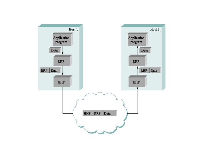
 Multiplexing & Demultiplexing • Same ideas apply up and down the protocol graph
 Examples of Network Architectures
 The protocol graph of Internet Applicatoin layer Transport layer Network layer Link layer • No strict layering. One can do cross-layer design • Hourglass shaped: IP defines a common method for exchanging packets among different networks • To propose a new protocol, one must produce both a spec and one/two implementations
 Functions of the Layers • Link Layer: – Service: – Functions: • Reliable transfer of frames over a link Media Access Control on a LAN Framing, media access control, error checking Network Layer: – Service: – Functions: Move packets from source host to destination host Routing, addressing • Transport Layer: – Service: Delivery of data between hosts – Functions: Connection establishment/termination, error control, flow control • Application Layer: – Service: Application specific (delivery of email, retrieval of HTML documents, reliable transfer of file) – Functions: Application specific
 architecture Seven-layer") The Open Systems Interconnection (OSI) architecture Seven-layer
The Open Systems Interconnection (OSI) architecture Seven-layer
 publishes protocol specs based on the OSI reference") • International Telecommunications Union (ITU) publishes protocol specs based on the OSI reference model – X dot series • Physical layer: handles raw bits • Data link layer: aggregate bits to frames. Network adaptors implement it • Network layer: handles host-to-host packet delivery. Data units are called packets • Transport: implements process channel. Data units are called messages • Session layer: handles multiple transport streams belong to the same applications • Presentation layer: data format, e. g. , integer format, ASCII string or not • Application layer: application specific protocols
• International Telecommunications Union (ITU) publishes protocol specs based on the OSI reference model – X dot series • Physical layer: handles raw bits • Data link layer: aggregate bits to frames. Network adaptors implement it • Network layer: handles host-to-host packet delivery. Data units are called packets • Transport: implements process channel. Data units are called messages • Session layer: handles multiple transport streams belong to the same applications • Presentation layer: data format, e. g. , integer format, ASCII string or not • Application layer: application specific protocols
 Summary of New Terms • Layering is an abstraction that captures important aspects of the system, provides service interfaces, and hides implementation details • Protocols are abstract objects that make up the layers of a network system are • A protocol graph represents protocols that make up a system – Nodes are protocols – Links are depend-on relations • Set of rules governing the form and content of a protocol graph are called a network architecture • Attaching a header/trailer to an upper layer data unit is referred to as encapsulation
 An Example
 A simple TCP/IP Example argon. tcpip-lab. edu ("Argon") neon. tcpip-lab. edu ("Neon") Web request Web page Web client Web server • A user on host argon. tcpip-lab. edu (“Argon”) makes web access to URL http: //neon. tcpip-lab. edu/index. html. • What actually happens in the network?
 HTTP Request and HTTP response • Web server runs an HTTP server program • HTTP client Web browser runs an HTTP client program • sends an HTTP request to HTTP server • HTTP server responds with HTTP response
 HTTP Request GET /example. html HTTP/1. 1 Accept: image/gif, */* Accept-Language: en-us Accept-Encoding: gzip, deflate User-Agent: Mozilla/4. 0 Host: 192. 168. 123. 144 Connection: Keep-Alive
 HTTP Response HTTP/1. 1 200 OK Date: Sat, 25 May 2002 21: 10: 32 GMT Server: Apache/1. 3. 19 (Unix) Last-Modified: Sat, 25 May 2002 20: 51: 33 GMT ETag: "56497 -51 -3 ceff 955" Accept-Ranges: bytes Content-Length: 81 Keep-Alive: timeout=15, max=100 Connection: Keep-Alive Content-Type: text/html
 From HTTP to TCP • To send request, HTTP client program establishes an TCP connection to the HTTP server Neon. • The HTTP server at Neon has a TCP server running
 Resolving hostnames and port numbers • Since TCP does not work with hostnames and also would not know how to find the HTTP server program at Neon, two things must happen: 1. The name “neon. tcpip-lab. edu” must be translated into a 32 -bit IP address. 2. The HTTP server at Neon must be identified by a 16 -bit port number.
 Translating a hostname into an IP address • The translation of the hostname neon. tcpip-lab. edu into an IP address is done via a database lookup – gethostbyname(host) • The distributed database used is called the Domain Name System (DNS) • All machines on the Internet have an IP address: argon. tcpip-lab. edu 128. 143. 137. 144 neon. tcpip-lab. edu 128. 143. 71. 21
 Finding the port number • Note: Most services on the Internet are reachable via well-known ports. E. g. All HTTP servers on the Internet can be reached at port number “ 80”. • So: Argon simply knows the port number of the HTTP server at a remote machine. • On most Unix systems, the well-known ports are listed in a file with name /etc/services. The well-known port numbers of some of the most popular services are: ftp 21 finger 79 telnet 23 http 80 smtp 25 nntp 119
&sin, sizeof(sin)) • The HTTP client at argon.") Requesting a TCP Connection connect(s, (struct sockaddr*)&sin, sizeof(sin)) • The HTTP client at argon. tcpip-lab. edu requests the TCP client to establish a connection to port 80 of the machine with address 128. 141. 71. 21
Requesting a TCP Connection connect(s, (struct sockaddr*)&sin, sizeof(sin)) • The HTTP client at argon. tcpip-lab. edu requests the TCP client to establish a connection to port 80 of the machine with address 128. 141. 71. 21
 Invoking the IP Protocol • The TCP client at Argon sends a request to establish a connection to port 80 at Neon • This is done by asking its local IP module to send an IP datagram to 128. 143. 71. 21 • (The data portion of the IP datagram contains the request to open a connection)
 Sending the IP datagram to the default router • Argon sends the IP datagram to its default router • The default gateway is an IP router • The default gateway for Argon is Router 137. tcpip -lab. edu (128. 143. 137. 1).
 Invoking the device driver • The IP module at Argon, tells its Ethernet device driver to send an Ethernet frame to address 00: e 0: f 9: 23: a 8: 20 • Ethernet address of the default router is found out via ARP
 The route from Argon to Neon • Note that the router has a different name for each of its interfaces.
 Sending an Ethernet frame • The Ethernet device driver of Argon sends the Ethernet frame to the Ethernet network interface card (NIC) • The NIC sends the frame onto the wire
 Forwarding the IP datagram • The IP router receives the Ethernet frame at interface 128. 143. 137. 1 1. recovers the IP datagram 2. determines that the IP datagram should be forwarded to the interface with name 128. 143. 71. 1 • The IP router determines that it can deliver the IP datagram directly
 Invoking the Device Driver at the Router • The IP protocol at Router 71, tells its Ethernet device driver to send an Ethernet frame to address 00: 20: af: 03: 98: 28
 Sending another Ethernet frame • The Ethernet device driver of Router 71 sends the Ethernet frame to the Ethernet NIC, which transmits the frame onto the wire.
 Data has arrived at Neon • Neon receives the Ethernet frame • The payload of the Ethernet frame is an IP datagram which is passed to the IP protocol. • The payload of the IP datagram is a TCP segment, which is passed to the TCP server
 Summary • Updated course administrative stuff – Grading policy, office hours, piazza • Design requirements of the original Internet • Concepts of Network Architectures • An Example of • how the Internet works