e27250528d2dbaabc4133425f3d973a8.ppt
- Количество слайдов: 26


Corporate Overview • Privately Held Company • Established in 1991 • Manufacturing and Distribution in: – North America (WI) – Europe (Sweden) – Asia (Hong Kong) • Yearly Growth Rate of 12 -20% • All Development in House • All Key Manufacturing in House

Company Target “Nimco aims at becoming the leading supplier of Electrical and Hydraulic Control Systems for customers that understand value exact motion control and use this feature to increase their competitiveness. ”

Manufacturing • Highly Automated Process – Valve Bodies run 20 -22 hours/day – 6 Full Production Days Per Week • Large CNC Machining Centers • Advanced Measurement Equipment for Quality Inspection • 100% Testing of All Products Before Dispatch • Lab testing and research facilities

Research and Development • All Design is made in Solid. Works® – All Design Engineers with M. Sc. In Hydraulics – Broad Knowledge of Valve and Motion Technology for Both Open Center and Load Sensing Systems

Open Center Spool Technology Minimized Internal Spool Leakage - Specially Developed High Precision Honing Method - High Precision Hard Chrome Centerless Grinded Spools - Radial Spool Grooves to Center the Spool in the Bore

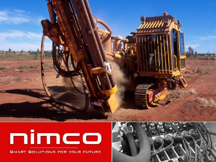
Application Example – Front End Loader SVL CV 152 CV 452 WK 300

Front Loader Valves

CV 112 – Front Loader Valve Design 2 Section Monoblock Flow Range 50 l/min 13 USgpm Max. Pressure 320 bar 4600 psi Circuits Port Sizes Controls Open Center Closed Center Pressure on Demand LS BSP G 3/8” • Manual Hand Lever • Cable Control • Mechanical Joystick • El. Hydr. Prop. Accessories • High Pressure Carry Over SAE #6

CV 152 – Front Loader Valve Design 2 Section Monoblock Flow Range 70 l/min 18 USgpm Max. Pressure 320 bar 4600 psi Circuits Port Sizes Controls Open Center Closed Center Pressure on Demand LS BSP G 3/8” SAE #6 • Manual Hand Lever • Cable Control • Mechanical Joystick w. Locking Mech. Accessories • High Pressure Carry Over • Quick Coupler

CV 432 & CV 432 S – Front Loader Valve Design Flow Range Max. Pressure Circuits Port Sizes Controls 2 Section Monoblock 100 l/min (OC) 70 l/min (S) 26 USgpm (OC) 18 USgpm (S) 320 bar 4600 psi Open Center (CV 432) Series Circuit (CV 432 S) BSP G 1/2” SAE #8 • Manual Hand Lever • Cable Control • Mechanical Joystick w. Locking Mech. Accessories • High Pressure Carry Over

CV 452 – Front Loader Valve Design Flow Range Max. Pressure Circuits Port Sizes Controls 2 Section Monoblock Special Purpose Valve 110 l/min 29 USgpm 320 bar 4600 psi Open Center Closed Center Pressure on Demand LS BSP G 1/2” SAE #10 • Manual Hand Lever • Cable Control • Mechanical Joystick w. Locking Mech. Accessories • Anti Shock Valves • Anti Cavitation Valves • High Pressure Carry Over • Multi Quick Coupler

EPCV 452 – Front Loader Valve Design Flow Range Max. Pressure Circuits Port Sizes 2 Section Monoblock Special Purpose Valve 110 l/min 29 USgpm 320 bar 4600 psi Open Center Closed Center Pressure on Demand LS BSP G 1/2” SAE #10 Controls • El. Hyd. Prop. Accessories • Available with pressure amplifier for tractors with low-stand by-pressure (EPCV 452 -LSP) • Anti Shock Valves • Anti Cavitation Valves • High Pressure Carry Over • Multi Quick Coupler

CV 652 – Front Loader Valve Design Flow Range Max. Pressure Circuits Port Sizes Controls 2 Section Monoblock Special Purpose Valve 120 l/min 32 USgpm 320 bar 4600 psi Open Center Closed Center Pressure on Demand LS BSP G 1/2” SAE #10 • Manual Hand Lever • Cable Control • Mechanical Joystick w. Locking Mech. Accessories • Anti Shock Valves • Anti Cavitation Valves • High Pressure Carry Over • Multi Quick Coupler

EPCV 652 – Front Loader Valve Design Flow Range Max. Pressure Circuits Port Sizes 2 Section Monoblock Special Purpose Valve 120 l/min 32 USgpm 320 bar 4600 psi Open Center Closed Center Pressure on Demand LS BSP G 1/2” SAE #10 Controls • El. Hyd. Prop. Accessories • Available with pressure amplifier for tractors with low-stand by-pressure (EPCV 452 -LSP) • Anti Shock Valves • Anti Cavitation Valves • High Pressure Carry Over • Multi Quick Coupler

Circuit Selector Valves

SVK Design 6/2 Circuit Selector Bankable up to three units Flow Range 50 l/min 24 USgpm Max. Pressure 280 bar 4100 psi Circuits Port Sizes Circuit Selector BSP G 3/8” SAE #6 Controls • Direct Acting Solenoid 12/24 VDC Accessories • Bolt-On Cross Over Relief Manifold

SVB Design 6/2 Circuit Selector Bankable up to three units Flow Range 90 l/min 24 USgpm Max. Pressure 280 bar 4100 psi Circuits Port Sizes Circuit Selector BSP G 1/2” SAE #8 Controls • Direct Acting Solenoid 12/24 VDC Accessories • Bolt-On Cross Over Relief Manifold

SVL Design 6/2 Circuit Selector Special Purpose Valve Bankable up to two units Flow Range 90 l/min 24 USgpm Max. Pressure 280 bar 4100 psi Circuits Port Sizes Circuit Selector BSP G 3/8” BSP G 1/2” SAE #6 SAE #8 Controls • Direct Acting Solenoid 12/24 VDC Accessories • Cross Over Relief Valves • Soft Ride Activation Valve - Electrical or Manual • Electrical Tool Locking Valve

Controls

WK 300 – Wire Control Design Key Features Wire Control Joystick – 1 or 2 axis • Reinforced Ergonomic Handgrip • Up to 3 El. Switches (6 A) • Easy to reach locking mechanism • Possibility to integrate customized logo or movement diagram on top of the handle • Robust and maintenance free • Easy to assemble • Possible to change the number of El. Switches

Epc 300 Design 2 -Axis Joystick 4 -20 m. A 0, 5 -4, 5 VDC 10 -30 VDC Options Output 4, 5 -5, 5 VDC Angular Operating Range Supply Voltage 10 -30 VDC Signals 0, 5 -4, 5 VDC X- and Y-axis: ± 20° 1 or 3 El. Push Buttons

CC 8 Design Analogue Joystick Control Card Supply Voltage • 10 -30 VDC Inputs • 8 Analogue Inputs (0 -5 VDC) Outputs • CAN-Bus Protocol • 5 VDC Reference Supply to Joystick CAN-bus Interface • 2. 0 B - 150 Hz Protection Class • IP 67 (In Standalone Version)

EDB 8 -64 Design I/O Driver Box 4+4 PWM Supply Voltage 10 -30 VDC Inputs CAN-Bus Protocol Outputs 8 (4+4) PWM Current Feedback 100 – 1800 m. A CAN-bus Interface 2. 0 B – 150 Hz Chopper Freq. 30/200 Hz Protection Class IP 67

EDB 16 -64 Design I/O Driver Box 8+8 PWM Supply Voltage • 10 -30 VDC Inputs • CAN-Bus Protocol • 8 Analogue Inputs (0 -5 VDC) Outputs • 16 (8+8) PWM Outputs • 1 Relay Output (4 A) Current Feedback • 100 – 1800 m. A CAN-bus Interface • 2. 0 B – 150 Hz Chopper Freq. • 30/200 Hz Protection Class • IP 67

Easy. Prog™ • Programming Software for Nimco Electronic Modules – Easy to Use and Intuitive – Logic Based Programming – Windows Based – Available in Three Languages • English • German • Swedish – Possibility to Remote Connect to System via GSM-Link • Trouble Shooting and Analysis • Maintenance and Update
e27250528d2dbaabc4133425f3d973a8.ppt