
CONTROL SYSTEM FLEXIBLE WIRING Executed from the hawsers


CONTROL SYSTEM FLEXIBLE WIRING Executed from the hawsers of type of КСАН - a rope is steel aviation ununtwisted Denotation: 7х7 A number of strands is in a rope A number of wires is in every strand Depending on the method of winding of separate strands in a rope Single winding Double winding (ПП - simple wickerwork) ((ТГ is a rope flexible, TOGAS - a rope is especially flexible)) (a diameter is a 1-2.5 mm)

CONTROL SYSTEM 1 2 3 4 1-tip with the left screw-thread; 2-muff; 3-tip with a right screw-thread; 4-locked wire Thunder for regulation of pull of rope A tip with a right screw-thread is put to direction of flight Screw-thread part of tips must be screwed in a muff on identical length The output of screw-thread part of tip is assumed no more than on 3 coils of screw-thread

Operation system Defects in flexible wiring Corrosion Залом Fracture Cold hardening Peening Dent Break in winding Friction in structural elements

Operation system Tension cable dependence from air temperature graph (1 for cables 2.5 mm diameter, 2 for cables 3.5 mm in diameter) Tension in cables at 20C must be: Trim Tab control РВ 23,0-32,0 кg Locking control surface & ailerons 23,0-32,0 кg Control mechanism АП 50-56 кg Nose landing gear rotation control 15-20 кг Tensometer ИН-11 1-lever; 2-cable; 3-nonremovable stop; Arrow fixation lever; replaceble stop; 6-scale

CONTROL SYSTEM Marking of hard thrust Aileron control Rudder control Elevator control Circular bands of black color On the thrust up to 500 mm ring bands in the middle of the traction are shown On the thrust up to 500 mm ring bands marked from two ends of thrust at a Distance of 10 mm from each end
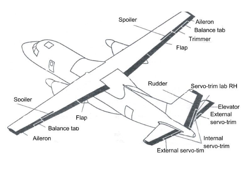

Operation Systems Ailerons Elevator Stabilizer Flaps Locking of control surfaces Spoilers Mechanisms КШ РН Trim tabs-Servotabs РН, РВ Right aileron trim tab Servotabs Cable disconnection

Cable wiring of АN-140 fuselage 1-leading quadrants 2-roller 3-directing 4-quadrant aileron operation 5-quadrant operation РВ 6-quadrant operation PH 7-cable

Scheme of the rudder control

Scheme of the elevator control

MANAGEMENT CHART BY AILERONS

1. support 2. drive of КПМ-02 3. propshafts 4. amuff of limitation moment 5. lift №1 6. support 7. reducing gear 8. mechanism of end-capping switches 9. support 10. lift № 2 11. reducing gear 12. block resistors of БР-48К 13. electric antiharvest brake 14. reducing gear 15. block of resistors of БР-48К 16. mechanism of МКВ-48КС EDITING OF CONTROL SYSTEM BY WING FLAPS ON BACKLONGERON RIGHT SEMIWING

GONIOMETER FOR HELM OF HEIGHTAND AILERONS 1 2 3 4 5 6 7 8 9 8 9 1. lever capture; 2. sponges; 3. hob; 4. screw; 5. ball-bearing; 6. axis; 7. nut; 8. scales; 9. plumb

Doskich - CONTROL SYSTEM DEFECTS OF THE FLEXIBLE WIRING Corrosion Hall peening Aspersion Dent Breakage of strings Friction about elements Designs

Doskich - CONTROL SYSTEM The chart of dependence of a tension of cables From temperature of air (1-for cables In diameter 2,5 mm; 2-for cables in diameter 3,5 mm) The tension of cables at 20°С should be: Management trimmer РВ 23,0-32,0 kg Latching of rudders and aileron 23,0-32,0 kg Steering car AP of 50-56 kg Management of turn of wheels Forward pillar of 15-20 kg Тensiometer ИН-11 The 1-lever; a 2-cable; a 3-fixed emphasis; The 4-lever of fixing of an arrow; 5-replaceable Emphasises; a 6-scale
9526-07-ac_control_system.ppt
- Количество слайдов: 15