

5ea4b92e0ecb8cc9c6a4bc2ee786eb2b.ppt
- Количество слайдов: 88
 Neville R. Watson,") Characteristics & Issues for Compact Fluorescent Lamps (AS/NZS EL 041 Meeting) Neville R. Watson, University of Canterbury 12 March 2008
Characteristics & Issues for Compact Fluorescent Lamps (AS/NZS EL 041 Meeting) Neville R. Watson, University of Canterbury 12 March 2008
 Outline 1. Background 2. Types of CFLs 3. Direct Harmonic Penetration Study 4. Detailed Transient Simulations 5. Other Studies 6. Standards 7. Conclusions
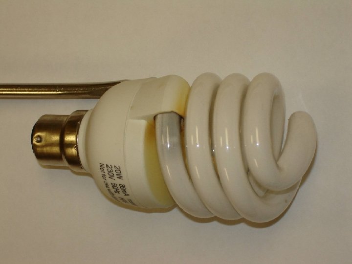
 Missing Components Fuse on Input Filter Capacitors missing
 Same brand September 2007 Does have PTC No Fuse No place for Filter Capacitors
 PTC missing
 3 rd Project 2008
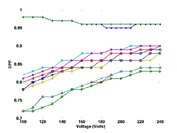
 Power-factor
 Types of CFL Ballasts
 Types of CFL § No Power-Factor Control § Passive Power-Factor Control § Valley-Filling (or equivalent) § Active Power-Factor Control
 Eclipse 20 W CFL
") OSRAM Dulux. Star 20 W (2007)
OSRAM Dulux. Star 20 W (2007)
") E-Lite CFL (July 2007)
E-Lite CFL (July 2007)
") Eco-Bulb (2007)
Eco-Bulb (2007)
 What is possible for a CFL for North American Market
 What is possible for a CFL
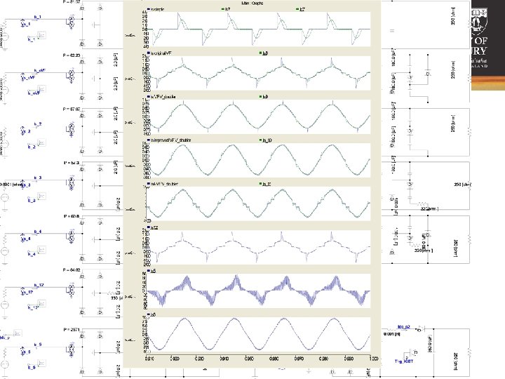
 Basic, no filtering Basic, with filtering Active Power-Factor Control Valley-fill or Equivalent
 Basic, no filtering Basic, with filtering Active Power-Factor Control Valley-fill or Equivalent
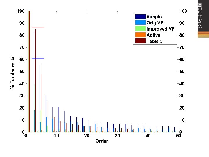
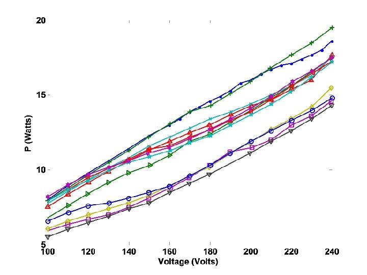
 Notice: form bands based on circuit type
 Analysis Methods
 Frequency Domain Analysis Direct Harmonic Penetration Study
 CFL Characteristics
 CFL Characteristics
 customers modelled") Test System 28, 800 (15 4 10 8 6) customers modelled
Test System 28, 800 (15 4 10 8 6) customers modelled
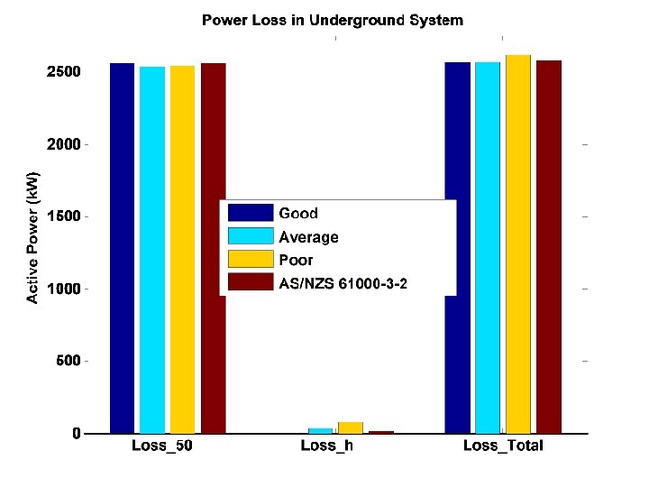
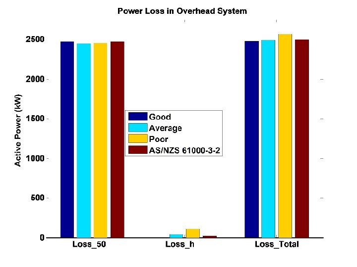
 Breakdown of Losses into Branches Branch No. Description 9 House Loads 8 Service Mains 7 LV Feeders 6 300 k. VA Transformers 5 11 k. V Feeders 4 33/11 k. V Transformers 3 33 k. V Feeders 2 33/220 k. V Transformers 1 220 k. V System
 Breakdown of Harmonic Losses into Frequencies
 This is like comparing apples and oranges
 Voltage Total Harmonic Distortion
 Distortion Level") 21 st Harmonic (1050 Hz) Distortion Level
21 st Harmonic (1050 Hz) Distortion Level
 Detailed Transient Simulations
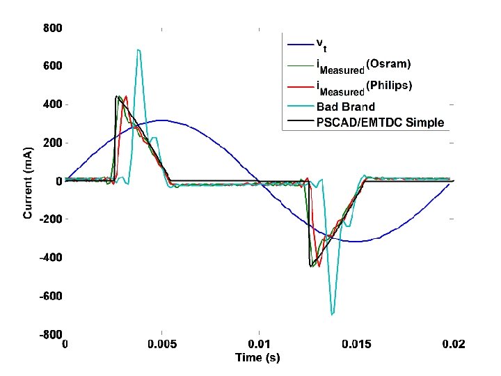
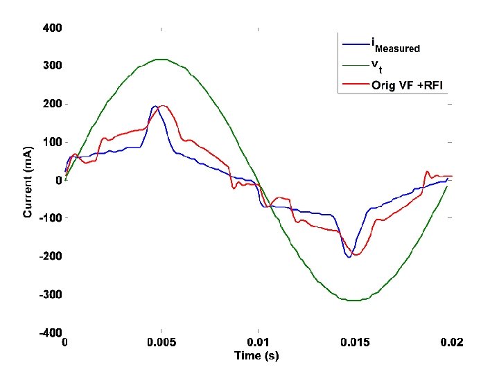
 Effect of voltage distortion on current waveform
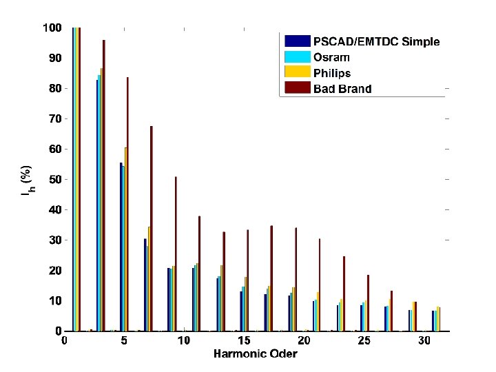
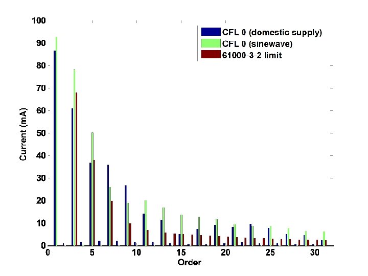
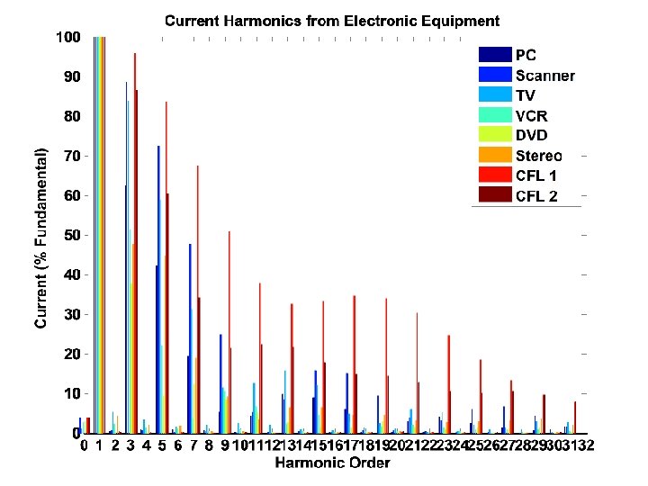
 Harmonics Very peaky current waveform rich in harmonics
 st 21 Harmonic Current
 st 21 Harmonic Current
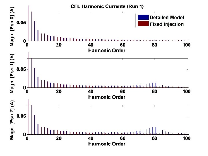
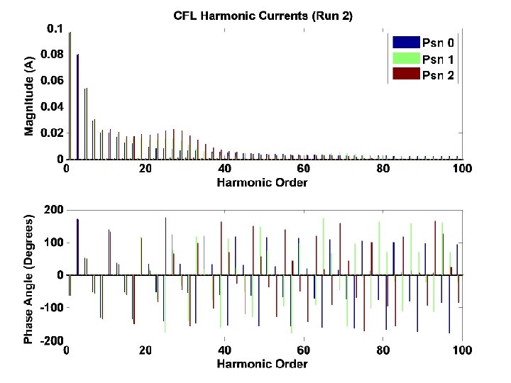
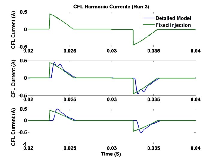
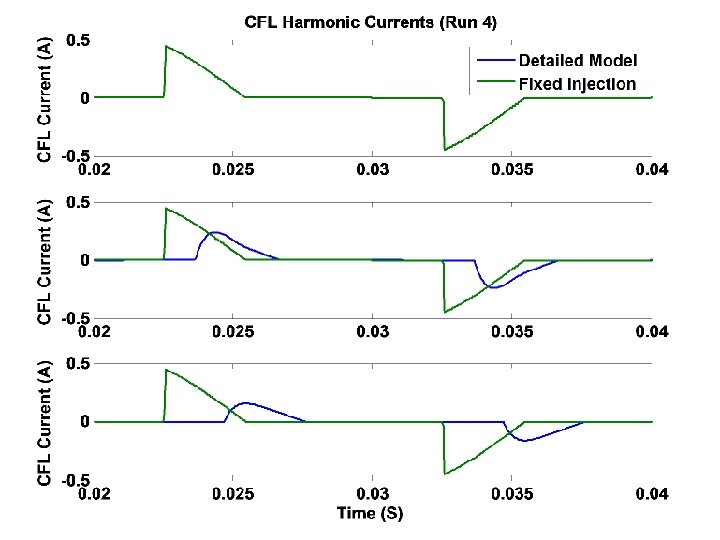
 4. Detailed Transient Simulations
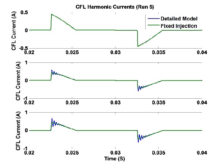
 Fixed Injection Model
 PSCAD/EMTDC Study SCR Loading 0. 1500 + j 0. 0750 pu 0. 4500 + j 0. 2250 pu R=0. 0075 L=8. 0214 e-5 Run 1 Load Point 1 = 5398. 7378 Run 5 Load Point 1 = 2699. 3689 Run 9 Load Point 1 = 1799. 579 R=0. 075 L=8. 0214 e-4 System Strength 0. 3000 + j 0. 1500 pu Run 2 Load Point 1 = 539. 8738 Run 6 Load Point 1 = 269. 9369 Run 10 Load Point 1 = 179. 9579 R=0. 75 L=8. 0214 e-3 Run 3 Load Point 1 = 53. 9874 Run 7 Load Point 1 = 26. 9937 Run 11 Load Point 1 = 17. 9958 R=7. 5 L=8. 0214 e-3 Run 4 Load Point 1 = 5. 3987 Run 8 Run 12 Load Point 1 = 2. 6994 Load Point 1 = 1. 7996
 Note magnification of injection for CFLs along feeder
 Magnification of Voltage along feeder
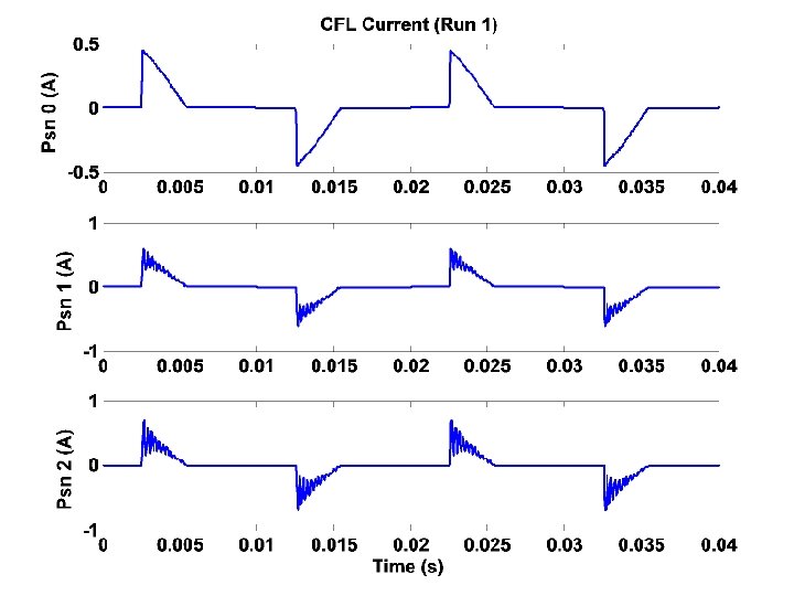
 Weaker system so oscillations at lower frequency
 Measurements made on a Domestic Supply Oscillations
 For each harmonic there is a system strength and loading where a maxima occurs Decreasing Increasing
 Decreasing Increasing
 For each harmonic there is a system strength and loading where a maxima occurs Decreasing Increasing
 Decreasing Increasing
 Other Studies
 5. Other studies Study 1: D. J. Pileggi, T. J. Gentile, A. E. Emanual, … et al, “The Effect of Modern Compact Fluorescent Lights On Voltage Distortion”, IEEE Trans. Of Power Delivery, Vol. 8, No. 4, Oct. 1993, pp 2038 -1042 Study 2: F. V. Topalis, “Efficiency Of Energy Saving Lamps And Harmonic Distortion In Distribution Systems”, IEEE Trans. of Power Delivery, Vol. 8, No. 4, Oct. 1993, pp 2038 -1042 Study 3: T. -M. Zhou, X. -Y. Zhu, Y. -L. He, W. Cheng and J. Schlejen, “Preliminary Investigation to the Effect of Harmonic Distortion by CFL on Quality of Electric Power Systems”, (Published? ) Study 4: N. Gothelf, Power Quality Effects of CFLs– A Field Study, RIGHT LIGHT 4, 1997 VOLUME 2, pp. 77 -81
 Study 1 “Electronically ballasted fluorescent lights with highly distorted current may jeopardize the reliability of the distribution system and the “quality” of the electric power delivered. ” D. J. Pileggi, T. J. Gentile, A. E. Emanual, … et al, “The Effect of Modern Compact Fluorescent Lights On Voltage Distortion”, IEEE Trans. Of Power Delivery, Vol. 8, No. 4, Oct. 1993, pp 2038 -1042
 Study 2 “These conclusions permit the formulation of the opinion that the extensive future use of the energy efficient lamps must be associated with simple and low cost filtering and power factor correction techniques” F. V. Topalis, “Efficiency Of Energy Saving Lamps And Harmonic Distortion In Distribution Systems”, IEEE Trans. of Power Delivery, Vol. 8, No. 4, Oct. 1993, pp 2038 -1042
 Study 3 T. -M. Zhou, X. -Y. Zhu, Y. -L. He, W. Cheng and J. Schlejen, “Preliminary Investigation to the Effect of Harmonic Distortion by CFL on Quality of Electric Power Systems” Four Cases: Single Lamp Home Lab retrofit Field Experiment
 Study 3 “Our experiments show that for CFL THD according to the new IEC 1000 proposal, in extremely high home applications (5 CFLs per home), the contribution to the V-THD is negligible, compared to TV and much less than computer. ”
 ? ? CFL 101 -103% (NZ") Home Experiment THDI PC 120% (NZ 66. 6%) ? ? CFL 101 -103% (NZ 120%) TV 90% (NZ 120%)
Home Experiment THDI PC 120% (NZ 66. 6%) ? ? CFL 101 -103% (NZ 120%) TV 90% (NZ 120%)
 Lab. Retrofit Test
 V-THD variation 1. 5 -2%. Experiment repeated 8 times
 Study 4 The test was divided in two phases: Phase 1: Measurements in a one-family house. The measurements were taken first without CFLs and then after installing five CFLs. Phase 2: Measurements in a residential district. The measurements were taken in a residential district consisting of 17 houses at existing load and then after installing of three and six CFLs respectively in each house.
 Study 4 “The study shows that replacement of incandescent lamps with CFLs is beneficial both for users and for utilities. The main advantages of CFLs are: - reduced energy consumption - long lifetime - released capacity of the distribution system High harmonic distortion is the main reason that utilities hesitate to advocate increased use of CFLs. They focus mainly on the high relative current distortion. It is true that for CFLs, the relative current distortion expressed in percent of the fundamental may exceed 100%. However, since fundamental current is very low …, the values of harmonic currents are very low too.
 Study 4 “The results indicate, that the harmonic generated by the CFLs in residential districts have only a minor effect on power quality of the supply network. ” N. Gothelf, Power Quality Effects of CFLs– A Field Study, RIGHT LIGHT 4, 1997 VOLUME 2, pp. 77 -81
 This current waveform is significantly better than most we see in sold in New Zealand
 Some of the Brands Tested § Basix § Marexim § Canopower § Mirabella § Connection § Nelson Lamps § Dura Lamp § No Frills § Eclipse § Osram § Ecobulb § Panasonic § Elite § Philips § Everyhome § Results § GE § Signature Range § Kempthorne § Smart. Lamp § Lux. Tec § Toshiba § Wotan
 Other Appliances
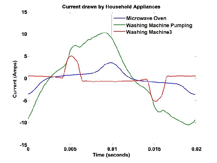
 Standard washing 1. 9 Amps THDI = 132% Spinning and Pumping 7. 9 Amps THDI = 34%
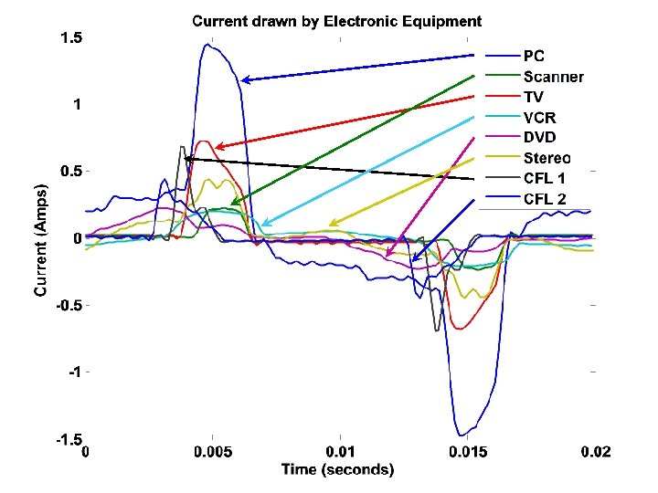
 Appliances Tested § TV § Microwave ovens § VCR § Mills § DVD § Halogen lights § Stereo § Fluorescent Lamps § Clock/radio § Fridge/freezers § Home entertainment systems § Freezers § PCs § Dryers § Monitors § Plug packs § Printers § Scanners § Washing machines
 Heat-pump tests 2008
 6. Conclusions § The wide-spread use of CFLs can be expected to reduce power quality. § The weaker networks exhibit less correlation in the harmonic current injection than stronger networks. § Resonances between CFL and ac network magnifies some frequency components (even for a relatively strong ac network)
 Acknowledgements § Tas Scott & Stephen Hirsch, Orion N. Z. Ltd § Vinod Kumar, Whisper Tech Limited § Joseph Lawrence, EPE Centre Manager § Lance Frater § Ken Smart § Geoff Neville, Enermet N. Z. Ltd.
 The End Any Questions?
") Valley Fill Circuit (Cct. 2)
Valley Fill Circuit (Cct. 2)
 Improved Valley Fill Circuit
 Active Power-Factor Control