

ba9172330ee0272969398a229d213562.ppt
- Количество слайдов: 55
 Chapter One TWO-PORT NETWORK TKT 419/3 Semester 2 Academic 2011/2012 Lecturer: Dr. Hilal Adnan (hilaladnan@unimap. edu. my)
Lecture : 3 hours per week for 14 weeks") Coursework Contribution 1. COURSE IMPLEMENTATIONS I)Lecture : 3 hours per week for 14 weeks (Total = 42 hours) Quiz and Assignment 20% Test 1&2 20 % Final Exam 60% Total 100% 2. Lecturer: Dr. Hilal A. Fadhil; and Prof. Dr. Syed A. Aljunid Office: 1 st Floor, House #8 A, KKF 34, K. wei- Kuala Perlis E-mail: hilaladnan@unimap. edu. my, Office tel#: 04 -9852639. 3. COURSE OUTLINE: Chapter 1 : Two-Port Circuits Chapter 2 : Introduction to Laplace Transform Chapter 3: Frequency Response in AC Circuit Chapter 4: Fourier Series Chapter 5: Fourier Transform 4. TEXT BOOK: Electric Circuits, 9 th Edition, by Nilsson/ Riedel
Coursework Contribution 1. COURSE IMPLEMENTATIONS I)Lecture : 3 hours per week for 14 weeks (Total = 42 hours) Quiz and Assignment 20% Test 1&2 20 % Final Exam 60% Total 100% 2. Lecturer: Dr. Hilal A. Fadhil; and Prof. Dr. Syed A. Aljunid Office: 1 st Floor, House #8 A, KKF 34, K. wei- Kuala Perlis E-mail: hilaladnan@unimap. edu. my, Office tel#: 04 -9852639. 3. COURSE OUTLINE: Chapter 1 : Two-Port Circuits Chapter 2 : Introduction to Laplace Transform Chapter 3: Frequency Response in AC Circuit Chapter 4: Fourier Series Chapter 5: Fourier Transform 4. TEXT BOOK: Electric Circuits, 9 th Edition, by Nilsson/ Riedel
 TWO-PORT NETWORK l. Terminal equations l. Two-port parameters l. Relationships among two-port parameters l. Analysis of terminated two-port circuit l. Interconnected two-port circuits
 TERMINAL EQUATIONS s-domain two-port basic building block
 Terminal equations relationships l 1 st Relationship:
 2 nd Relationship:
 3 rd Relationship:
 4 th Relationship:
 5 th Relationship:
 6 th Relationship:
 TWO PORT NETWORK: l. Terminal equations l. Two-port parameters l. Relationships between parameters l. Analysis of terminated two-port circuit l. Interconnected two-port circuits
 IMPEDANCE PARAMETERS lz parameters
 ADMITTANCE PARAMETERS y parameters
 a parameters
 b parameters a and b parameters are called transmission parameters
 HYBRID PARAMETERS h parameters
 INVERSE HYBRID PARAMETERS g parameters
 Example 1 l. Find z parameter for the below circuit:
 Solutions: l. When port 2 open-circuit, I 2=0 so,
 l. When I 2=0, thus V 2
 Now, when I 1=0, so
 l. When port 1 open-circuit, I 1=0, so:
 TWO-PORT NETWORK l. Terminal equations l. Two-port parameters l. Relationships between parameters l. Analysis of terminated two-port circuit l. Interconnected two-port circuits
 RELATIONSHIPS BETWEEN PARAMETERS
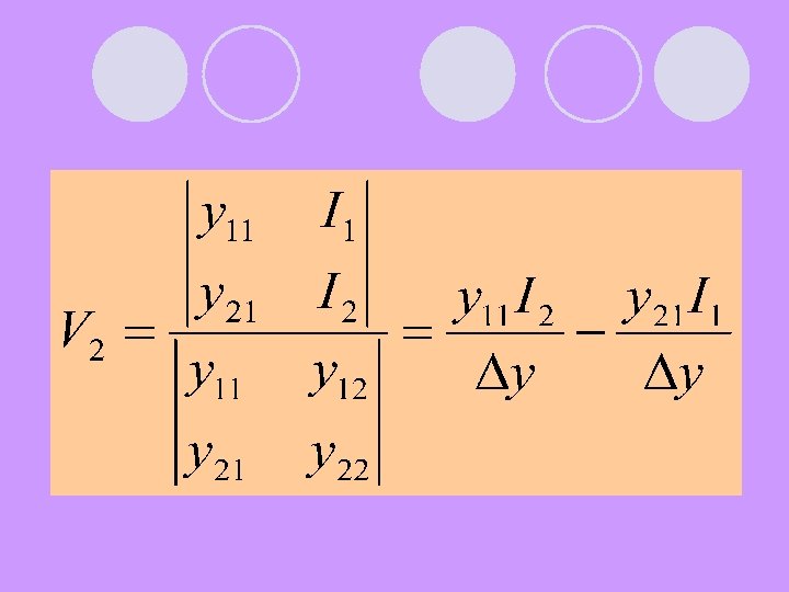
 Compare these two above equations:
 Find z parameters as functions of a parameters
 Therefore,
 RECIPROCAL TWO-PORT CIRCUITS l If a two-port circuit is reciprocal, the following relationships exist among port parameters:
 Symmetric of a reciprocal two-port circuits l Following relationships exist among port parameters:
 Example of symmetric two-port circuits Symmetric tee
 Symmetric pi
 Symmetric bridge tee
 Symmetric lattice
 TWO-PORT NETWORK l. Terminal equations l. Two-port parameters l. Relationships between parameters l. Analysis of terminated two-port circuit l. Interconnected two-port circuits
 ANALYSIS OF TERMINATED TWOPORT CIRCUITS
 or admittance") 6 characteristics of terminated two-port circuit l Input impedance (Zin=V 1/I 1) or admittance (Yin=I 1/V 1) l Output current, I 2 l Thevenin voltage and impedance (ZTh, VTh) with respect to port 2 l Current gain I 2/I 1 l Voltage gain V 2/Vg
6 characteristics of terminated two-port circuit l Input impedance (Zin=V 1/I 1) or admittance (Yin=I 1/V 1) l Output current, I 2 l Thevenin voltage and impedance (ZTh, VTh) with respect to port 2 l Current gain I 2/I 1 l Voltage gain V 2/Vg
 6 characteristics in term of z parameters l 4 parameter equations that describe the circuit: … 1 … 2 … 3 … 4
 In Eq(2) we replace V 2 with –I 2") 1 st characteristic (input impedance) In Eq(2) we replace V 2 with –I 2 ZL and solve for I 2 …. . (5) Then substitute this Eq into eq(1), Zin=V 1/I 1
1 st characteristic (input impedance) In Eq(2) we replace V 2 with –I 2 ZL and solve for I 2 …. . (5) Then substitute this Eq into eq(1), Zin=V 1/I 1
 We solve Eq. (1) for I 1") 2 nd characteristic (output current, I 2) We solve Eq. (1) for I 1 after replacing V 1 with the right-hand side of Eq. (3) the result is : Then using Eq(5)
2 nd characteristic (output current, I 2) We solve Eq. (1) for I 1 after replacing V 1 with the right-hand side of Eq. (3) the result is : Then using Eq(5)
 But V 1=Vg-I 1 Zg , and") 3 rd characteristic (Thevenin voltage @ impedance) But V 1=Vg-I 1 Zg , and then I 1= Vg/(Zg+Z 11)
3 rd characteristic (Thevenin voltage @ impedance) But V 1=Vg-I 1 Zg , and then I 1= Vg/(Zg+Z 11)
, Eq(3) reduces to:") Impedance Thevenin WHEN Vg is replacing by a short circuit (Vg=0), Eq(3) reduces to: V 1=-I 1 Zg Substituting the above eq into Eq(1) gives: ……(6) Now use Eq(6) to replace Eq(2) with the result that:
Impedance Thevenin WHEN Vg is replacing by a short circuit (Vg=0), Eq(3) reduces to: V 1=-I 1 Zg Substituting the above eq into Eq(1) gives: ……(6) Now use Eq(6) to replace Eq(2) with the result that:
 From equation (5), the current gain is given by:") 4 th characteristic (current gain) From equation (5), the current gain is given by:
4 th characteristic (current gain) From equation (5), the current gain is given by:
 By replacing I 2 in Eq.") 5 th characteristic (voltage gain V 2/V 1) By replacing I 2 in Eq. (2) with its value from Eq. (4); thus: …. . 7 …. . 8
5 th characteristic (voltage gain V 2/V 1) By replacing I 2 in Eq. (2) with its value from Eq. (4); thus: …. . 7 …. . 8
 with Eq. (8) and solve the") We now replace I 1 in Eq. (7) with Eq. (8) and solve the resulting expression for V 2/V 1:
We now replace I 1 in Eq. (7) with Eq. (8) and solve the resulting expression for V 2/V 1:
 To derive the voltage ratio V 2/Vg,") 6 th characteristic (voltage gain V 2/Vg) To derive the voltage ratio V 2/Vg, we first combine Eqs(1) (3)(4) to find I 1 as a function of V 2 and Vg : …. (9) We now use Eq. (9) and Eq(4) in conjunction with Eq. (2) to derive an expression involving only V 2 and Vg; that is:
6 th characteristic (voltage gain V 2/Vg) To derive the voltage ratio V 2/Vg, we first combine Eqs(1) (3)(4) to find I 1 as a function of V 2 and Vg : …. (9) We now use Eq. (9) and Eq(4) in conjunction with Eq. (2) to derive an expression involving only V 2 and Vg; that is:
 Finally, we can manipulate to get the desired voltage ratio:
 TWO-PORT NETWORK l. Terminal equations l. Two-port parameters l. Relationships between parameters l. Analysis of terminated two-port circuit l. Interconnected two-port circuits
 INTERCONNECTED TWO-PORT CIRCUITS
 Cascade connection
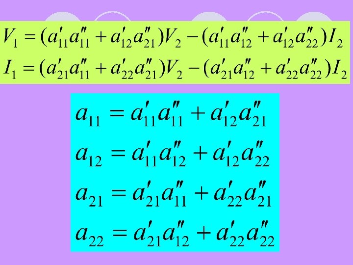
 Two-port parameters
") Interconnection (V’ 2=V’ 1 and I’ 2= -I’ 1)
Interconnection (V’ 2=V’ 1 and I’ 2= -I’ 1)
 Relationship V’ 1 and I’ 1 with V 2 and I 2 in second circuit :
 Reference book l. Electric Circuits, James W. Nilsson and Susan A. Riedel, Prentice Hall