
Chapter 9 Longitudinal Hull strength Stress definitions mechanical


 Regulation 3-1: Structural, mechanical and electrical requirements")


 force,")


")
")


 case, a load on a barge that")


=Area under the load curve")


7896-chapter_9_longitudinal_hull_strength.ppt
- Количество слайдов: 61
Chapter 9 Longitudinal Hull strength
Stress definitions mechanical property of materials Beam theory of ship strength Shear and bending moment diagram
Longitudinal strength is needed for a bridge over troubled waters!
Containership splits in two The afterpart of the 25-year-old container ship CARLA after breaking in two during a storm 100 miles off the Azores. The disaster occurred after the ship's rudder was damaged, leaving her at the mercy of the heavy seas. The 34-man crew, who took shelter in the stern section, were all taken off by helicopter. The forward half sank after five days, but a tug managed to tow the stern section, carrying 1,000 containers, to Las Palmas. The ship was lengthened 1984, but the vessel's owners denies that the ship had broken apart along one of the welds.
- Old ship? - Too heavy cargo? - Not properly maintained? - Wrong operation when loading?
Green sea on deck requires a strong deck structure
Causes of cracks in the strength deck and in the shell NOBODY IS PERFECT !
SOLAS Part A-1 (Structure of Ship) Regulation 3-1: Structural, mechanical and electrical requirements for ships In addition to the requirements contained elsewhere in the present regulations, ships shall be designed, constructed and maintained in compliance with the structural, mechanical and electrical requirements of a classification society which is recognized by the Administration in accordance with the provisions of regulation XI/ 1, or with applicable national standards of the Administration which provide an equivalent level of safety
International Convention on Load Lines, 1966 Regulation 1: Strength of Hull The Administration shall satisfy itself that the general structural strength of the hull is sufficient for the draught corresponding to the free-board assigned. Ships built and maintained in conformity with the requirements of a classification society recognized by the Administration may be considered to possess adequate strength.
1. Preliminary stress definitions 1. Tension or tensile stress The forces are acting in such a direction as to increase the length 2. Compression or compressive stress The forces are acting in such a direction as to decrease the length. Extension of the material Compression of the material
3. Shearing stress Two equal forces are acting along parallel lines and in opposite directions such that the various parts of the section tend to slide one on the other.
4. Load Load refers to the total acting on a member or a structure and is expressed usually in tons or pounds. We can actually compare the longitudinal distribution of weight and the longitudinal distribution of buoyancy. This upward and downward forces cause shear stress through the hull, which result in placing the deck and bottom plating in either tension or compression
If the applied force, F, consists of two equal and opposite parallel forces, not in the same line, then there is a tendency for one part to slide over the other or shear across the section
5. Strain is the lengthening or distortion of a member due to stress. Its unit are expressed in elongation or distortion per unit.
2. Mechanical Properties of Metals Plasticity is the ease with which a material may be bent or moulded into a given shape. Ductility is the property of a material which allows it to be drawn out into smaller sections. Brittleness is the lack of ductility. Fatigue is the loss of ductility and consequent failure at a lower load after repeated application of alternating stress Malleability is the property possessed by a metal which allows it to be rolled or hammered without fracture. Such material must be plastic. Hardness is the measure of a metal's resistance to surface indentation and abrasion. Elasticity is the property by virtue of which a material deformed under load returns to its original shape when the load is removed. Strength is the ability of the material to resist fracture under load. Toughness is the property whereby a material absorbs energy with-out fracture or has the ability to resist the propagation of cracks.
Forces in the material When the material is subject to a longitudinal (axial) force, also a lateral (internal) force will be set up (because of the change of the sectional area and by that the volume)
As shown by the dotted lines, changes also occur in the cross-sectional area of the material and thus strains are set up in lateral directions as well as longitudinal directions.
Hooke's Law For loading within the elastic limit of the material, deformation is directly proportional to the load producing it. Since stress is proportional to load and strain to deformation, then stress is proportional to strain. The ratio of stress to strain is a constant for a given material. Assuming all strains to lie within the elastic limit so that all stresses follow Hooke's Law, then the intensity of stress, б, at any point is: б = E·x/l = E·ε where E is the modulus of elasticity or Young's modulus Stress N/mm2 Elongation mm or %
E is not a function of the strength of the material but is a function of its flexibility E is the modulus of elasticity or Young's modulus ESTEEL 2·105 N/mm2 EAl 0,69·105 N/mm2
Stress / Strain diagram – Low carbon steel
Stress / Strain Diagram – Low carbon steel
Stress / Strain Diagram – Low carbon steel
Failure modes against which structures must be designed in a gross sense, include: Hull failure Deck collapse Bulkhead collapse Cracking and loss of water tightness Gross deflections
In a more finite sense, geometry and material failures or strength loss include: Tearing Fracture Cracking Rupture Explosion Buckling Crippling Tripping Collapse Excessive deflection Corrosion Pitting Wastage Creep Fatigue Warping Shearing Compressive plastic flow Lamellar tearing
Minimum necessary plate thickness RULE VALUE for a new ship SAFETY MARGIN because of: Inaccurate calculation, varying plate thickness, welding influence MINIMUM THICKNESS To maintain sufficient strength with acceptable safety margin
3. Beam theory of ship strength
The ship looks like a beam
The ship itself and all the construction details are like beams For the purpose of calculating the maximum vertical bending stresses and moment the ship may be considered as a beam (box girder). There are then simple formulas for detecting the maximum stresses.
The hull of a ship is like a beam with various loads and supports
Beam Theory When a force, or a system of forces, is imposed upon a beam or girder resulting in a bending moment, the beam will tend to bend by an amount that will depend on the magnitude of the bending moment.
Three geometric properties of a structure are of importance when considering the longitudinal stress distribution in a beam subjected to bending: Neutral Axis of the beam is the position of the unstrained layer in longitudinal bending; the neutral axis is coincident with the centroid or centre of gravity of a section. Second Moment of Area or Moment of Inertia of the section (I) is said to be the measure of a beam's ability to resist deflection. It is an indication of how the cross-sectional area is distributed with respect to the neutral axis. Section Modulus of the cross-section (Z) is a measure of the structural bending strength of the section under consideration. Z = I/ymax, y is the distance from the extreme edge to the neutral axis. Then, M = I/y x σ, σ is maximum stress
Second moment of area = Moment of inertia The Second Moment of Area (I) of a rectangular section of length l and breadth b about an axis through the centroid (neutral axis) and parallel to the breadth: where A = area of cross-section NA = neutral axis
Example. A steel beam is 40cm deep and 5cm wide, the bending moment at the middle of its length is 15 tons meter. Find the maximum stress on the steel. I = lb3/12 = 5 x 403/12 = 80000/3 cm4 f = M/I x y , and y = d/2 = 40/2 = 20 cm Neutral axis 5cm 40cm f = 15 x 20 x 3 / 80000 tons per cm2 = 1.125 tons per cm2
The Application of beam theory to the ship 1. The maximum reasonable load, which the hull of a vessel considered as a girder or beam, will be called upon to assume. This load will consist of three things: A reasonably severe condition of loading A still water condition c. A reasonably severe sea condition 2. The bending moment and shear resulting from this maximum reasonable load are stresses computed by use of shear and bending moment diagram 3. The section modulus (Z) necessary to withstand with a proper margin of safety, the calculated bending moment, and the resulting tensile and compressive stress in the upper and lower flanges of the hull girder.
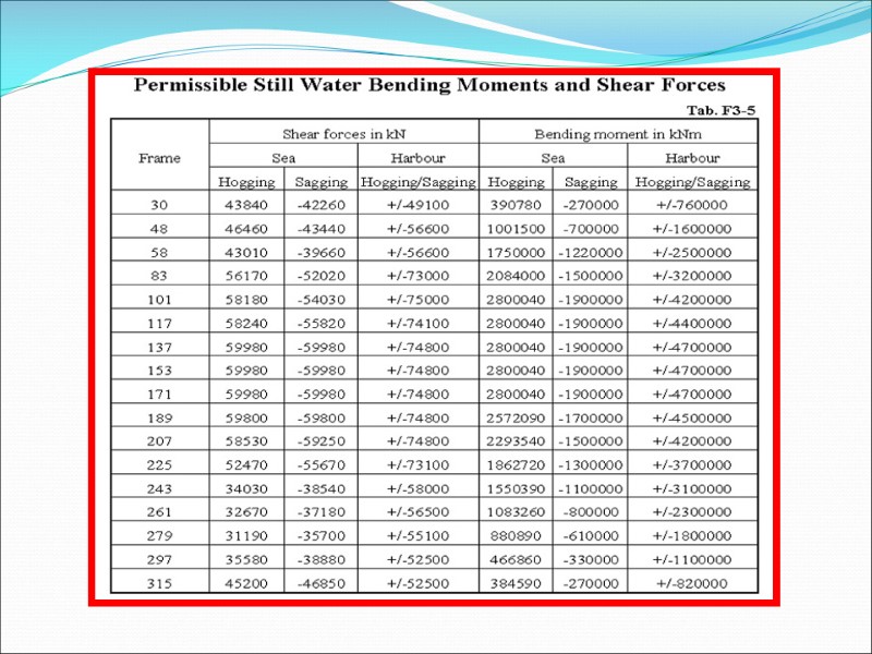
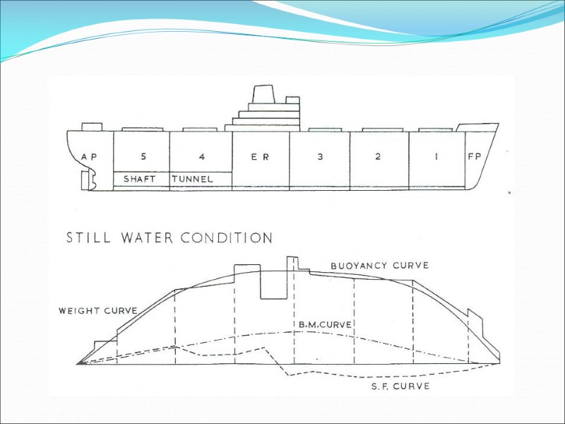
Still Water Bending Moment (S.W.B.M.)
Deformation of a container ship in the seaway (deformation magnified)
2017/12/8 Hogging sagging
4. Shearing and bending moment diagrams
Divide the length of the ship into a number of equal parts. Calculate the average weight per meter for each of the sections. Calculate the average buoyancy per meter for each of the sections. Draw the loading diagram as a series of rectangles. Successive integration of the load curve will give the values for the shearing force and bending moment curves. Check that the total weight and total buoyancy are equal and they have the same fore and aft position for the L CB and L C G.
G B WL Ds and FB are equal in magnitude, acting through the centroid points G and B respectively The centroids of the forces are vertically in line How to draw a loading diagram
In reality, the buoyant forces act as a distributed force, FB barge Uniformly distributed buoyant force, FB In this case, the distributed force acts on the uniform hull of a barge, so the force can be considered uniformly distributed.
barge Likewise, the weight of the ship is really a distributed load (or a combination of both point and distributed loads)…. In this case, it is a uniformly distributed load.
barge In this most simple (and unrealistic!) case, a load on a barge that is uniformly distributed will be opposed by the uniformly distributed buoyant force. w = 2LT/ft 50 ft FB = w x L = 2LT/ft x 50ft = 100LT wFB = 2LT/ft
barge 1 LT/ft 2 LT/ft 4 LT/ft 2 LT/ft 1 LT/ft A more realistic case involves a non-uniformly distributed load. In this case with a uniformly shaped barge, the resulting FB will still be a uniformly distributed reaction load, wFB,(provided there is only parallel sinkage!)
1 LT/ft 2 LT/ft 4 LT/ft 2 LT/ft 1 LT/ft wB = 2 LT/ft By summing up the distributed load of the ship with the distributed load of the buoyant force, you can obtain the Load Diagram... (+) (-) (-) (-) (-) (-) Shear plane
1 LT/ft 1 LT/ft 2 LT/ft A B C D E F 10ft 10ft 10ft 10ft 10ft By examining the resulting Load Diagram, you can easily pick out the points that will experience the maximum shear stress... … maximum shear stress occurs where the load diagram crosses the x-axis.
1 LT/ft 1 LT/ft 2 LT/ft A B C D E F A shear diagram illustrates this fact; maximum stresses occur where the load diagram crosses the x-axis (or equals 0). -10 LT +10 LT Load Diagram Shear Diagram
The bending moment at any section in a beam is defined as the sum of the moments, about that section, of all the forces acting on one side or on the other side of that section. Moment to left of section X Y is equal to the moment to the right of section X Y since the beam is in a state of equilibrium. Bending moment: M = R1d3 - W l d l - W2d2 Bending Moment
The bending moment diagram shows the variation in the bending moment along the length of the beam. BENDING MOMENT diagram R1= W/2 R1= W/2 Mmax= R ·L/2 = W·L/4
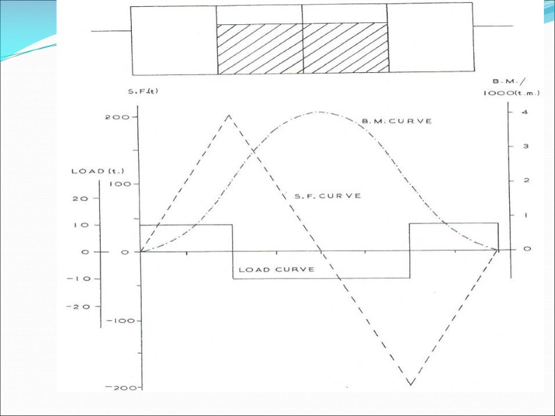
Example: A barge is of rectangular construction; length 80 metre, breadth 10 metre, depth 6 metre, floating at a draught of 3 metre in fresh water. It is divided transversely into four equal compartments; the two centre compartments are to be uniformly loaded with 400 tonne cargo in each. Draw the curves of load, shear force and bending moment for the loaded condition.
S.F= shear force=Σ(vertical forces)=Area under the load curve
B.M. = bending moment = Area under the shear force curve
The shearing force and bending moment in the beam are shown graphically by plotting the values of the shearing force and bending moment at points along the beam. Such curves indicate where fracture is most likely to occur; that is at points where the shearing force or bending moment has its maximum value. 1. Increase in the bending moment between two sections is given by the area under the shearing force curve between those sections; 2. Generally zero shearing force corresponds to a maximum or minimum bending moment; 3. Peaks in the bending moment diagram frequently occur at points of concentrated loads or reactions; 4. Area of the shear force diagram above the baseline equals the area below the baseline.
Shear and bending moment curves for a ship in waves
Typical strength curves
How to Reduce Shear Stress of ship Change the underwater hull shape so that buoyancy distribution matches that of weight distribution - The step like shape is very inefficient with regard to the resistance - Since the loading condition changes every time, this method isn’t feasible Concentrate the ship hull strength in areas where large shear stress exists - use higher strength material - increase the cross sectional area of the structure
Reducing the Effect of Bending stress Bending moment are largest at midship of a ship. Ship will experience the greatest bending stress at the deck and keel The bending stress can be reduced by using: - higher strength steel - larger cross sectional area of longitudinal structural elements