

51b44aeaa73d5d69afc4aee19d75b488.ppt
- Количество слайдов: 156
 Chapter 6 Medium Access Control Protocols and Local Area Networks Part I: Medium Access Control Part II: Local Area Networks
 Chapter Overview Broadcast Networks All information sent to all users No routing Shared media Radio Cellular telephony Wireless LANs Medium Access Control Local Area Networks Copper & Optical Ethernet LANs Cable Modem Access To coordinate access to shared medium Data link layer since direct transfer of frames High-speed, low-cost communications between co-located computers Typically based on broadcast networks Simple & cheap Limited number of users
 Chapter 6 Medium Access Control Protocols and Local Area Networks Part I: Medium Access Control Multiple Access Communications Random Access Scheduling Channelization Delay Performance
 Chapter 6 Medium Access Control Protocols and Local Area Networks Part II: Local Area Networks Overview of LANs Ethernet Token Ring and FDDI 802. 11 Wireless LAN Bridges
 Chapter 6 Medium Access Control Protocols and Local Area Networks Multiple Access Communications
 Multiple Access Communications Shared media basis for broadcast networks Inexpensive: radio over air; copper or coaxial cable M users (two or more nodes) communicate by broadcasting into medium: interference collision if node receives two or more signals at the same time Key issue: How to share the medium? multiple access protocol distributed algorithm that determines how nodes share channel, i. e. , determine when node can transmit 3 1 2 4 Shared multiple access medium M 5
 Approaches to Media Sharing Medium sharing techniques Dynamic medium access control Static channelization Partition medium /channel (time slots, frequency, code) Dedicated allocation to users E. g. Satellite transmission, Cellular Telephone Scheduling Polling: take turns Request for slot in transmission schedule E. g. Token ring, Wireless LANs Random access Loose coordination (no partition, allow collisions) Send, wait, retry if necessary E. g. Aloha, Ethernet
 Medium sharing techniques Channelization: Satellite uplink fin downlink fout Satellite communication: Shared radio using two frequency bands, one for transmitting and one for receiving
 Medium sharing techniques Channelization: Cellular uplink f 1 ; downlink f 2 uplink f 3 ; downlink f 4 Cellular telephony: Two frequency bands shared by a set of mobile users
 Medium sharing techniques Scheduling: Polling Data from 1 from 2 Data Poll 1 Host computer Inbound line Data to M Poll 2 Outbound line 1 2 M 3 Stations Host computer issues polling messages to each terminal, providing it with permission to transmit on the inbound line
 Medium sharing techniques Scheduling: Token-Passing Ring networks token Data to M token Station that holds token transmits into ring
 Medium sharing techniques Random Access Multitapped Bus Crash!! Transmit when ready Collision can occur; need retransmission strategy
 Wireless LAN Ad. Hoc: station-to-station Infrastructure: stations to base station Random access & polling Shared wireless medium (2. 4 HGz radio)
 Selecting a Medium Access Control Applications Scale What type of traffic? Voice streams? Steady traffic, low delay/jitter Data? Short messages? Web page downloads? Enterprise or Consumer market? Reliability, cost How much traffic can be carried? How many users can be supported? Current Examples: Design MAC to provide wireless DSL-equivalent access to rural communities Design MAC to provide Wireless-LAN-equivalent access to mobile users (user in car travelling at 130 km/hr)
 Delay-Bandwidth Product Delay-bandwidth product key parameter Coordination in sharing medium involves using bandwidth (explicitly or implicitly) Difficulty of coordination commensurate with delay -bandwidth product Simple two-station example Station with frame to send listens to medium and transmits if medium found idle Station monitors medium to detect collision If collision occurs, station that begin transmitting earlier retransmits (propagation time is known)
 Two-Station MAC Example Two stations are trying to share a common medium A transmits at t = 0 Distance d meters tprop = d / seconds A B Case 1 A B Case 2 A A detects collision at t = 2 tprop B A B B does not transmit before t = tprop & A captures channel B transmits before t = tprop and detects collision soon thereafter
 Efficiency of Two-Station Example Each frame transmission requires 2 tprop of quiet time Station B needs to be quiet tprop before and after time when Station A transmits R transmission bit rate L bits/frame Normalized Delay. Bandwidth Product Propagation delay Time to transmit a frame
 protocol: Token-ring network If a<<1, then efficiency") Typical MAC Efficiencies Two-Station Example: CSMA-CD (Ethernet) protocol: Token-ring network If a<<1, then efficiency close to 100% As a approaches 1, the efficiency becomes low a΄= latency of the ring (bits)/average frame length
Typical MAC Efficiencies Two-Station Example: CSMA-CD (Ethernet) protocol: Token-ring network If a<<1, then efficiency close to 100% As a approaches 1, the efficiency becomes low a΄= latency of the ring (bits)/average frame length
 Typical Delay-Bandwidth Products Distance 10 Mbps 1 m 3. 33 x 10 -02 100 Mbps 1 Gbps 3. 33 x 10 - 3. 33 x 100 01 Network Type Desk area network 100 m 3. 33 x 1001 3. 33 x 1002 3. 33 x 1003 Local area network 10 km 3. 33 x 1002 3. 33 x 1003 3. 33 x 1004 Metropolitan area network 1000 km 3. 33 x 1004 3. 33 x 1005 100000 km 3. 33 x 1006 3. 33 x 1007 3. 33 x 1006 Wide area network 3. 33 x 1008 Global area network Max size Ethernet frame: 1500 bytes = 12000 bits Long and/or fat pipes give large a
 MAC protocol features Delay-bandwidth product Efficiency Transfer delay Fairness Reliability Capability to carry different types of traffic Quality of service Cost
 MAC Delay Performance Frame transfer delay Throughput From first bit of frame arrives at source MAC To last bit of frame delivered at destination MAC Actual transfer rate through the shared medium Measured in frames/sec or bits/sec Parameters R bits/sec & L bits/frame X=L/R seconds/frame l frames/second average arrival rate Load r = l X, rate at which “work” arrives Maximum throughput (@100% efficiency): R/L fr/sec
![Normalized Delay versus Load E[T]/X E[T] = average frame transfer delay Transfer delay X](https://present5.com/presentation/51b44aeaa73d5d69afc4aee19d75b488/image-22.jpg "Normalized Delay versus Load E[T]/X E[T] = average frame transfer delay Transfer delay X") Normalized Delay versus Load E[T]/X E[T] = average frame transfer delay Transfer delay X = average frame transmission time 1 Load rmax 1 r At low arrival rate, only frame transmission time At high arrival rates, increasingly longer waits to access channel Max efficiency typically less than 100%
Normalized Delay versus Load E[T]/X E[T] = average frame transfer delay Transfer delay X = average frame transmission time 1 Load rmax 1 r At low arrival rate, only frame transmission time At high arrival rates, increasingly longer waits to access channel Max efficiency typically less than 100%
![Dependence on Rtprop/L a > a E[T]/X a Transfer Delay a 1 r max](https://present5.com/presentation/51b44aeaa73d5d69afc4aee19d75b488/image-23.jpg "Dependence on Rtprop/L a > a E[T]/X a Transfer Delay a 1 r max") Dependence on Rtprop/L a > a E[T]/X a Transfer Delay a 1 r max Load rmax 1 r
Dependence on Rtprop/L a > a E[T]/X a Transfer Delay a 1 r max Load rmax 1 r
 Chapter 6 Medium Access Control Protocols and Local Area Networks Random Access Protocol
 ALOHA Wireless link to provide data transfer between main campus & remote campuses of University of Hawaii Simplest solution: just do it A station transmits whenever it has data to transmit If more than one frames are transmitted, they interfere with each other (collide) and are lost If ACK not received within timeout, then a station picks random backoff time (to avoid repeated collision) Station retransmits frame after backoff time First transmission t 0 -X t 0 Backoff period B Retransmission t t 0+X Vulnerable period t 0+X+2 tprop Time-out t 0+X+2 tprop + B
 Random access protocols when node has packet to send two or more transmitting nodes ➜ “collision”, random access MAC protocol specifies: transmit at full channel data rate R. no a priori coordination among nodes how to detect collisions how to recover from collisions (e. g. , via delayed retransmissions) examples of random access MAC protocols: ALOHA slotted ALOHA CSMA, CSMA/CD, CSMA/CA
 ALOHA v v v Aloha: no synchronization when frame first arrives transmit immediately v If collision occur, immediately retransmit frame with probability p. v Or wait for frame transmission time, and retransmit with probability p collision probability high: § frame sent at t 0 collides with other frames sent in [t 0 -1, t 0+1]
 S: throughput (average") ALOHA Model Definitions and assumptions X frame transmission time (assume constant) S: throughput (average # successful frame transmissions per X seconds) G: load (average # transmission attempts per X sec. ) Psuccess : probability a frame transmission is successful X Prior interval X frame transmission Any transmission that begins during vulnerable period leads to collision Success if no arrivals during 2 X seconds
ALOHA Model Definitions and assumptions X frame transmission time (assume constant) S: throughput (average # successful frame transmissions per X seconds) G: load (average # transmission attempts per X sec. ) Psuccess : probability a frame transmission is successful X Prior interval X frame transmission Any transmission that begins during vulnerable period leads to collision Success if no arrivals during 2 X seconds
 Abramson’s Assumption What is probability of no arrivals in vulnerable period? Abramson assumption: Effect of backoff algorithm is that frame arrivals are equally likely to occur at any time interval G is avg. # arrivals per X seconds Divide X into n intervals of duration D=X/n p = probability of arrival in D interval, then G = n p since there are n intervals in X seconds
 Throughput of ALOHA e-2 = 0. 184 Collisions are means for coordinating access Max throughput is rmax= 1/2 e (18. 4%) Bimodal behavior: Small G, S≈G Large G, S↓ 0 Collisions can snowball and drop throughput to zero
 Slotted ALOHA Time is slotted in X seconds slots Stations synchronized to frame times Stations transmit frames in first slot after frame arrival Backoff intervals in multiples of slots Backoff period k. X (k+1)X Vulnerabl eperiod t 0 +X+2 tprop B t t 0 +X+2 tprop+ B Time-out Only frames that arrive during prior X seconds collide
 Throughput of Slotted ALOHA 0. 368 S 0. 184 Ge-G Ge-2 G G
 Application of Slotted Aloha cycle . . . Reservation mini-slots X-second slot Reservation protocol allows a large number of stations with infrequent traffic to reserve slots to transmit their frames in future cycles Each cycle has mini-slots allocated for making reservations Stations use slotted Aloha during mini-slots to request slots
 A station senses the channel before it starts transmission") Carrier Sensing Multiple Access (CSMA) A station senses the channel before it starts transmission If busy, either wait or schedule backoff (different options) If idle, start transmission Vulnerable period is reduced to tprop (due to channel capture effect) When collisions occur they involve entire frame transmission times If tprop >X (or if a>1), no gain compared to ALOHA or slotted ALOHA Station A begins transmission at t=0 Station A captures channel at t = tprop A A
Carrier Sensing Multiple Access (CSMA) A station senses the channel before it starts transmission If busy, either wait or schedule backoff (different options) If idle, start transmission Vulnerable period is reduced to tprop (due to channel capture effect) When collisions occur they involve entire frame transmission times If tprop >X (or if a>1), no gain compared to ALOHA or slotted ALOHA Station A begins transmission at t=0 Station A captures channel at t = tprop A A
") CSMA Options Transmitter behavior when busy channel is sensed 1 -persistent CSMA (most greedy) Start transmission as soon as the channel becomes idle Low delay and low efficiency Non-persistent CSMA (least greedy) Wait a backoff period, then sense carrier again High delay and high efficiency p-persistent CSMA (adjustable greedy) Wait till channel becomes idle, transmit with prob. p; or wait one mini-slot time & re-sense with probability 1 -p Delay and efficiency can be balanced Sensing
CSMA Options Transmitter behavior when busy channel is sensed 1 -persistent CSMA (most greedy) Start transmission as soon as the channel becomes idle Low delay and low efficiency Non-persistent CSMA (least greedy) Wait a backoff period, then sense carrier again High delay and high efficiency p-persistent CSMA (adjustable greedy) Wait till channel becomes idle, transmit with prob. p; or wait one mini-slot time & re-sense with probability 1 -p Delay and efficiency can be balanced Sensing
 1 -Persistent CSMA Throughput S 0. 53 0. 45 a = 0. 01 0. 16 a =0. 1 G a=1 Better than Aloha & slotted Aloha for small a Worse than Aloha for a > 1
 Non-Persistent CSMA Throughput a = 0. 01 S 0. 81 0. 51 a = 0. 14 G a=1 Higher maximum throughput than 1 -persistent for small a Worse than Aloha for a > 1
 Monitor for collisions & abort transmission Stations with frames") CSMA with Collision Detection (CSMA/CD) Monitor for collisions & abort transmission Stations with frames to send, first do carrier sensing After beginning transmissions, stations continue listening to the medium to detect collisions If collisions detected, a short jamming signal is transmitter to ensure all station knows there is a collision, abort transmission, reschedule random backoff times, and try again at scheduled times In CSMA collisions result in wastage of X seconds spent transmitting an entire frame CSMA-CD reduces wastage to time to detect collision and abort transmission
CSMA with Collision Detection (CSMA/CD) Monitor for collisions & abort transmission Stations with frames to send, first do carrier sensing After beginning transmissions, stations continue listening to the medium to detect collisions If collisions detected, a short jamming signal is transmitter to ensure all station knows there is a collision, abort transmission, reschedule random backoff times, and try again at scheduled times In CSMA collisions result in wastage of X seconds spent transmitting an entire frame CSMA-CD reduces wastage to time to detect collision and abort transmission
 CSMA/CD reaction time A begins to transmit at A t=0 B A detects collision at A t= 2 tprop- B B begins to transmit at t = tprop ; B detects collision at t = tprop It takes 2 tprop to find out if channel has been captured
 CSMA-CD Model Assumptions Collisions can be detected and resolved in 2 tprop Time slotted in 2 tprop slots during contention periods Assume n busy stations, and each may transmit with probability p in each contention time slot Once the contention period is over (a station successfully occupies the channel), it takes X seconds for a frame to be transmitted It takes tprop before the next contention period starts. (a) Busy Contention Busy Idle Contention Busy Time
") Contention Resolution How long does it take to resolve contention? Contention is resolved (“success’) if exactly 1 station transmits in a slot: By taking derivative of Psuccess we find max occurs at p=1/n On average, 1/Pmax = e = 2. 718 time slots to resolve contention
Contention Resolution How long does it take to resolve contention? Contention is resolved (“success’) if exactly 1 station transmits in a slot: By taking derivative of Psuccess we find max occurs at p=1/n On average, 1/Pmax = e = 2. 718 time slots to resolve contention
 CSMA/CD Throughput Busy Contention Busy Time At maximum throughput, systems alternates between contention periods and frame transmission times where: R bits/sec, L bits/frame, X=L/R seconds/frame a = tprop/X meters/sec. speed of light in medium d meters is diameter of system 2 e+1 = 6. 44
 Example The distance, from 3 terminal to the hub is 50 meters, the transmission lines speed is 2. 5 x 10⁸ bps, all frames are of length, L=12, 500 bytes, and the signal propagates on the line at a speed of v=2. 5 x 10⁸ meter/second. Calculate the maximum network throughput, achievable when the hub is implementing CSMACD. Assume that the average number of minislots, e until a station successfully captures the channel is 2. 718 minislots. Pmax = Max. Throughput = 1/(1+(2 e+1)a) where a = Tprop / X Tprop = distance / propagation speed = 50 / 2. 5 x 108 = 2 x 10 -7 s X = Frame length / bit rate = (12500 x 8 bits)/(10 x 106) = 0. 01 s => a = 2 x 10 -7/0. 01 = 2 x 10 -5 Therefore, Max. Throughput = 1/(1+(6. 44 x 2 x 10 -5) = 1/1. 0000036 = 0. 99987
 CSMA-CD Application: Ethernet First Ethernet LAN standard used CSMA-CD 1 -persistent Carrier Sensing R = 10 Mbps tprop = 51. 2 microseconds 512 bits = 64 byte slot accommodates 2. 5 km + 4 repeaters Truncated Binary Exponential Backoff After nth collision, select backoff from {0, 1, …, 2 k – 1}, where k=min(n, 10)
 Throughput for Random Access MACs CSMA/CD 1 -P CSMA Non-P CSMA max Slotted ALOHA a For small propagation delay, a: CSMA-CD has best throughput For larger a: Aloha & slotted Aloha better throughput
 Carrier Sensing and Priority Transmission Certain applications require faster response than others, e. g. ACK messages Impose different interframe times High priority traffic sense channel for time t 1 Low priority traffic sense channel for time t 2>t 1 High priority traffic, if present, seizes channel first This priority mechanism is used in IEEE 802. 11 wireless LAN
 SUMMARY when node has packet to send two or more transmitting nodes ➜ “collision”, random access MAC protocol specifies: transmit at full channel data rate R. no a priori coordination among nodes how to detect collisions how to recover from collisions (e. g. , via delayed retransmissions) examples of random access MAC protocols: ALOHA slotted ALOHA CSMA, CSMA/CD, CSMA/CA
 Medium sharing techniques Dynamic medium access control Static channelization Partition medium /channel (time slots, frequency, code) Dedicated allocation to users E. g. Satellite transmission, Cellular Telephone Scheduling Polling: take turns Request for slot in transmission schedule E. g. Token ring, Wireless LANs Random access • ALOHA • slotted ALOHA • CSMA/CD • CSMA/CA
 Chapter 6 Medium Access Control Protocols and Local Area Networks Scheduling
 Scheduling for Medium Access Control Schedule frame transmissions to avoid collision in shared medium ü ü ü û More efficient channel utilization Less variability in delays Can provide fairness to stations Increased computational or procedural complexity Two main approaches Reservation Polling
 Reservation Systems Reservation Frame interval transmissions r d r d Cycle n = 1 2 3 d r d d d Cycle (n + 1) Time M Stations take turns transmitting a single frame at the full rate R bps Transmissions organized into cycles Cycle: reservation interval + frame transmissions Reservation interval has a minislot for each station to request reservations for frame transmissions Cycle length (variable) based on the number of stations that have a frame to transmit.
 Reservations Systems Centralized systems: A central controller accepts requests from stations and issues grants to transmit Frequency Division Duplex (FDD): Separate frequency bands for uplink & downlink Time-Division Duplex (TDD): Uplink & downlink time-share the same channel Distributed systems: Stations implement a decentralized algorithm to determine transmission order Central Controller
 r 3") Example Initially stations 3 & 5 have reservations to transmit frames (a) r 3 5 r 3 5 8 r 3 t Station 8 becomes active and makes reservation Cycle now also includes frame transmissions from station 8 (b) 8 r 3 5 8 r 3 t
Example Initially stations 3 & 5 have reservations to transmit frames (a) r 3 5 r 3 5 8 r 3 t Station 8 becomes active and makes reservation Cycle now also includes frame transmissions from station 8 (b) 8 r 3 5 8 r 3 t
 Example: GPRS General Packet Radio Service Packet data service in GSM cellular radio GPRS devices, e. g. cellphones or laptops, send packet data over radio and then to Internet Slotted Aloha MAC used for reservations Single & multi-slot reservations supported
 Polling Systems Reservation systems required stations to make reservation to gain access to the transmission medium Polling system : - stations take turns accessing the medium Centralized polling systems: A central controller transmits polling messages to stations according to a certain order Distributed polling systems: A permit for frame transmission is passed from station to station according to a certain order A signaling procedure exists for setting up order Central Controller
 Polling System Options Service Limits: How much is a station allowed to transmit per poll? Exhaustive: until station’s data buffer is empty (including new frame arrivals) Gated: all data in buffer when poll arrives Frame-Limited: one frame per poll Time-Limited: up to some maximum time Priority mechanisms More bandwidth & lower delay for stations that appear multiple times in the polling list Issue polls for stations with message of priority k or higher
 Application Examples Single-frame reinsertion Single token reinsertion IBM Token Ring @ 4 Mbps Multitoken reinsertion IEEE 802. 5 Token Ring LAN @ 4 Mbps IEEE 802. 5 and IBM Ring LANs @ 16 Mbps FDDI Ring @ 50 Mbps All of these LANs incorporate token priority mechanisms
 Comparison of MAC approaches Aloha & Slotted Aloha Simple & quick transfer at very low load Accommodates large number of low-traffic bursty users Highly variable delay at moderate loads Efficiency does not depend on a CSMA-CD Quick transfer and high efficiency for low delay-bandwidth product Can accommodate large number of bursty users Variable and unpredictable delay
 Comparison of MAC approaches Reservation On-demand transmission of bursty or steady streams Accommodates large number of low-traffic users with slotted Aloha reservations Can incorporate Qo. S Handles large delay-bandwidth product via delayed grants Polling Generalization of time-division multiplexing Provides fairness through regular access opportunities Can provide bounds on access delay Performance deteriorates with large delay-bandwidth product
 Medium sharing techniques Dynamic medium access control Static channelization Partition medium /channel (time slots, frequency, code) Dedicated allocation to users E. g. Satellite transmission, Cellular Telephone Scheduling Reservation system: Request for slot in transmission schedule Polling: take turns E. g. Token ring, Wireless LANs Random access • ALOHA • slotted ALOHA • CSMA/CD • CSMA/CA
 Chapter 6 Medium Access Control Protocols and Local Area Networks Channelization
 Why Channelization? Channelization Semi-static bandwidth allocation of portion of shared medium to a given user Approaches Frequency Division Multiple Access (FDMA) Time Division Multiple Access (TDMA) Frequency band allocated to users Broadcast radio & TV, analog cellular phone Periodic time slots allocated to users Telephone backbone, GSM digital cellular phone Code Division Multiple Access (CDMA) Code allocated to users Cellular phones, 3 G cellular
 Why Channelization? PRO Highly efficient for constant-bit rate traffic Preferred approach in Cellular telephone networks Terrestrial & satellite broadcast radio & TV CONS Inflexible in allocation of bandwidth to users with different requirements Inefficient for bursty traffic Does not scale well to large numbers of users Average transfer delay increases with number of users M Dynamic MAC much better at handling bursty traffic
 Guard bands A guard band is an unused part of the radio spectrum between radio bands, for the purpose of preventing interference
 Guardbands FDMA Frequency bands must be non-overlapping to prevent interference Guardbands ensure separation; form of overhead TDMA Stations must be synchronized to common clock Time gaps between transmission bursts from different stations to prevent collisions; form of overhead Must take into account propagation delays
 Channelization in Cellular Telephone Networks Cellular networks use frequency reuse Band of frequencies reused in other cells that are sufficiently far that interference is not a problem Cellular networks provide voice connections which is steady stream Techniques implemented in cellular network FDMA used in AMPS TDMA used in IS-54 and GSM CDMA used in IS-95
 First generation cellular telephone system in US Analog voice") Advanced Mobile Phone System (AMPS) First generation cellular telephone system in US Analog voice channels of 30 k. Hz Forward channels from base station to mobiles Reverse channels from mobiles to base Frequency band 50 MHz wide in 800 MHz region allocated to two service providers: “A” and “B” A A B AB A A B Frequency 824 MHz 849 MHz 869 MHz 894 MHz
Advanced Mobile Phone System (AMPS) First generation cellular telephone system in US Analog voice channels of 30 k. Hz Forward channels from base station to mobiles Reverse channels from mobiles to base Frequency band 50 MHz wide in 800 MHz region allocated to two service providers: “A” and “B” A A B AB A A B Frequency 824 MHz 849 MHz 869 MHz 894 MHz
 AMPS Spectral Efficiency 50 MHz @ 30 k. Hz gives 832 2 -way channels Each service provider has 416 2 -way channels 21 channels used for call setup & control 395 channels used for voice AMPS uses 7 -cell frequency reuse pattern, so each cell has 395/7 voice channels AMPS spectrum efficiency: #calls/cell/MHz (395. 7)/(25 MHz) = 2. 26 calls/cell/MHz
 IS-54, and later IS-136, developed to meet demand for cellular") Interim Standard 54/136 (IS-54) IS-54, and later IS-136, developed to meet demand for cellular phone service Digital methods to increase capacity A 30 -k. Hz AMPS channel converted into several TDMA channels 1 AMPS channel carries 48. 6 kbps stream Stream arranged in 6 -slot 40 ms cycles 1 slot = 324 bits → 8. 1 kbps per slot 1 full-rate channel: 2 slots to carry 1 voice signal 1 AMPS channel carries 3 voice calls 30 k. Hz spacing also used in 1. 9 GHz PCS band
Interim Standard 54/136 (IS-54) IS-54, and later IS-136, developed to meet demand for cellular phone service Digital methods to increase capacity A 30 -k. Hz AMPS channel converted into several TDMA channels 1 AMPS channel carries 48. 6 kbps stream Stream arranged in 6 -slot 40 ms cycles 1 slot = 324 bits → 8. 1 kbps per slot 1 full-rate channel: 2 slots to carry 1 voice signal 1 AMPS channel carries 3 voice calls 30 k. Hz spacing also used in 1. 9 GHz PCS band
 IS-54 TDMA frame structure Base to mobile 6 2 1 3 4 5 1 6 3 2 Time Mobile to base 1 2 3 4 5 6 1 2 3 4 40 ms 416 AMPS channels x 3 = 1248 digital channels Assume 21 channels for calls setup and control IS-54 spectrum efficiency: #calls/cell/MHz (1227/7)/(25 MHz) = 3 calls/cell/MHz Time
 European digital cellular telephone system 890 -915 MHz") Global System for Mobile Communications (GSM) European digital cellular telephone system 890 -915 MHz & 935 -960 MHz band PCS: 1800 MHz (Europe), 1900 MHz (N. Am. ) Hybrid TDMA/FDMA Carrier signals 200 k. Hz apart 25 MHz give 124 one-way carriers Existing services 890 MHz Initial GSM 905 MHz reverse 915 MHz Existing services 935 MHz Initial GSM 950 MHz forward 960 MHz
Global System for Mobile Communications (GSM) European digital cellular telephone system 890 -915 MHz & 935 -960 MHz band PCS: 1800 MHz (Europe), 1900 MHz (N. Am. ) Hybrid TDMA/FDMA Carrier signals 200 k. Hz apart 25 MHz give 124 one-way carriers Existing services 890 MHz Initial GSM 905 MHz reverse 915 MHz Existing services 935 MHz Initial GSM 950 MHz forward 960 MHz
 GSM TDMA Structure Each carrier signal carries traffic and control channels 1 full rate traffic channel = 1 slot in every traffic frame 24 slots x 114 bits/slot / 120 ms = 22. 8 kbps Slow Associated Control Channel Traffic Channels #0 -11 0 1 2 3 4 5 6 7 8 Traffic Channels #13 -24 9 10 11 12 13 14 15 16 17 18 19 20 21 22 23 24 25 1 multiframe = 26 frames 120 ms long 0 1 Slow Associated Control Channel 2 3 4 5 6 7 1 TDMA frame = 8 slots 1 slot = 114 data bits / 156. 25 bits total
 GSM Spectrum Efficiency Error correction coding used in 22. 8 kbps to carry 13 kbps digital voice signal Frequency reuse of 3 or 4 possible 124 carriers x 8 = 992 traffic channels Spectrum efficiency for GSM: (992/3)/50 MHz = 6. 61 calls/cell/MHz
 Chapter 6 Medium Access Control Protocols and Local Area Networks Part II: Local Area Networks Overview of LANs Ethernet Token Ring and FDDI 802. 11 Wireless LAN Bridges
 Chapter 6 Medium Access Control Protocols and Local Area Networks Overview of LANs
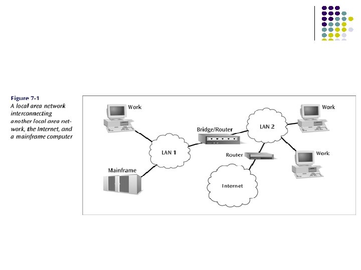
 between") What is a LAN? Local area means: Private ownership Short distance (~1 km) between computers low cost very high-speed, relatively error-free communication complex error control unnecessary Machines are constantly moved freedom from regulatory constraints of WANs Keeping track of location of computers a chore Simply give each machine a unique address Broadcast all messages to all machines in the LAN Need a medium access control protocol
What is a LAN? Local area means: Private ownership Short distance (~1 km) between computers low cost very high-speed, relatively error-free communication complex error control unnecessary Machines are constantly moved freedom from regulatory constraints of WANs Keeping track of location of computers a chore Simply give each machine a unique address Broadcast all messages to all machines in the LAN Need a medium access control protocol
") Typical LAN Structure Ethernet Processor RAM ROM RAM Transmission Medium Network Interface Card (NIC) Unique MAC “physical” address
Typical LAN Structure Ethernet Processor RAM ROM RAM Transmission Medium Network Interface Card (NIC) Unique MAC “physical” address
 RECALL… D wants to send an IP datagram to C and knows C’s IP address. Identify whether D needs to know C’s MAC addresses to send the datagram to C. Explain your answer. Yes, since C is on the same subnet, it will need to know C’s MAC address.
 RECALL… D wants to send an IP datagram to B and knows C’s IP address. Identify whether D needs to know B’s MAC addresses to send the datagram to B. Explain your answer. No, D will forward the frame to the router, and the router will then de-capsulate the datagram and then reencapsulate the datagram in a frame to be sent over the right subnet.
 to") RECALL… Suppose that R has a datagram (that was originally sent by D) to send to B. FIND. . . Source IP address: Destination IP address: 111. 112 Source MAC address: 222. 221 E 6 -E 9 -00 -17 -BB-4 B (right interface of R) Destination MAC address: CC-49 -DE-D 0 -AB-7 D
RECALL… Suppose that R has a datagram (that was originally sent by D) to send to B. FIND. . . Source IP address: Destination IP address: 111. 112 Source MAC address: 222. 221 E 6 -E 9 -00 -17 -BB-4 B (right interface of R) Destination MAC address: CC-49 -DE-D 0 -AB-7 D
 Data Link layer: Sub-layer OSI IEEE 802 Network layer LLC Network layer 802. 2 Logical link control Data link layer 802. 11 802. 3 802. 5 MAC CSMA-CD Token Ring Wireless LAN Physical layer Various physical layers Other LANs Physical layer
 Data Link layer: Sub-layer In IEEE 802. 1, Data Link Layer divided into: 1. Medium Access Control Sub-layer Coordinate access to medium Connectionless frame transfer service Machines identified by MAC/physical address Broadcast frames with MAC addresses Logical Link Control Sub-layer – Covered in previous chapter 2. Between Network layer & MAC sub-layer Error Control, sequencing, flow control, etc
 Logical Link Control Layer IEEE 802. 2: LLC enhances service provided by MAC C A A Unreliable Datagram Service Reliable frame service C LLC LLC MAC MAC MAC PHY PHY PHY
 Token ring") LAN • Common LAN Systems – Ethernet (1 st commercially available LAN) Token ring – FDDI (fiber data distributed interface) ring –
LAN • Common LAN Systems – Ethernet (1 st commercially available LAN) Token ring – FDDI (fiber data distributed interface) ring –
 A bit of history… 1970 ALOHAnet radio network deployed in Hawaiian islands 1973 Metcalf and Boggs invent Ethernet, random access in wired net 1979 DIX Ethernet II Standard 1985 IEEE 802. 3 LAN Standard (10 Mbps) 1995 Fast Ethernet (100 Mbps) 1998 Gigabit Ethernet 2002 10 Gigabit Ethernet is the dominant LAN standard Metcalf’s Sketch
 IEEE 802. 3 MAC: Ethernet MAC Protocol: CSMA/CD Slot Time is the critical system parameter upper bound on time to detect collision upper bound on time to acquire channel upper bound on length of frame segment generated by collision quantum for retransmission scheduling max{round-trip propagation, MAC jam time} Truncated binary exponential backoff for retransmission n: 0 < r < 2 k, where k=min(n, 10) Give up after 16 retransmissions
 Ethernet or CSMA/CD Most common form of LAN today. Star-wired bus is most common topology but bus topology also around. Ethernet comes in many forms depending upon medium used and transmission speed and technology. 88
 Ethernet Originally, CSMA/CD was 10 Mbps. Then 100 Mbps was introduced. Most NICs sold today are 10/100 Mbps. Then 1000 Mbps (1 Gbps) was introduced. 10 Gbps is now available. 1000 Mbps introduces a few interesting wrinkles: Transmission is full duplex (separate transmit and receive), thus no collisions. Prioritization is possible using 802. 1 p protocol. Topology can be star or mesh (for trunks). 89
 or optical (but 10 Gbps") Ethernet Cabling can be either UTP (unshielded twisted pair) or optical (but 10 Gbps Ethernet may not work over UTP due to radio frequency interference). Where 10 Mbps Ethernet has less than 30% utilization due to collisions, 1000 Mbps is limited only by traffic queueing. Distance with 10 Mbps is limited by CSMA/CD propagation time, whereas 1000 Mbps limited only by media. 90
Ethernet Cabling can be either UTP (unshielded twisted pair) or optical (but 10 Gbps Ethernet may not work over UTP due to radio frequency interference). Where 10 Mbps Ethernet has less than 30% utilization due to collisions, 1000 Mbps is limited only by traffic queueing. Distance with 10 Mbps is limited by CSMA/CD propagation time, whereas 1000 Mbps limited only by media. 90
 91
91
 IBM Token Ring Deterministic LAN offered at speeds of 4, 16 and 100 Mbps using star-ring topology. Very good throughput under heavy loads. More expensive components than CSMA/CD. Losing ground quickly to CSMA/CD. May be extinct soon. 92
 Based on the token ring design using 100 Mbps") FDDI (Fiber Distributed Data Interface) Based on the token ring design using 100 Mbps fiber connections. Allows for two concentric rings - inner ring can support data travel in opposite direction or work as backup. Token is attached to the outgoing packet, rather than waiting for the outgoing packet to circle the entire ring. 93
FDDI (Fiber Distributed Data Interface) Based on the token ring design using 100 Mbps fiber connections. Allows for two concentric rings - inner ring can support data travel in opposite direction or work as backup. Token is attached to the outgoing packet, rather than waiting for the outgoing packet to circle the entire ring. 93
 FDDI Dual ring becomes a single ring A E B C D 94
 High-Speed backplane or interconnection fabric Single collision domain HUB SWITCHES
 Typical Ethernet Deployment Server farm Server Switch/router Server Ethernet switch 100 Mbps links Hub 10 Mbps links Department A Server Gigabit Ethernet links Ethernet switch 100 Mbps links Server Hub 10 Mbps links Department B Switch/router Ethernet switch 100 Mbps links Server Hub 10 Mbps links Department C
 LANs In Action : A Small Office Solution What type of system will interconnect 20 workstations in one room and 15 workstations in another room to a central server, which offers: • Internal e-mail • A database that contains all customer information • High quality printer access
 98 Wiring diagram of the office space that shows the placement of hubs and servers
 LANs In Action : A Home Office Local Area Network Solution What if you have two computers at home and want both to share a printer and a connection to the Internet.
 Chapter 6 Medium Access Control Protocols and Local Area Networks 802. 11 Wireless LAN
 Wireless Data Communications Wireless communications compelling ü ü ü Easy, low-cost deployment Mobility & roaming: Access information anywhere Supports personal devices ü ü Supports communicating devices ü û û û PDAs, laptops, data-cell-phones Cameras, location devices, wireless identification Signal strength varies in space & time Signal can be captured by snoopers Spectrum is limited & usually regulated
 Ad Hoc Communications C A B D Temporary association of group of stations Within range of each other Need to exchange information E. g. Presentation in meeting, or distributed computer game, or both
 Infrastructure Network Portal Distribution System Server Gateway to Portal the Internet AP 1 AP 2 A 1 BSS A B 2 A 2 BSS B Permanent Access Points provide access to Internet
 A C Data Frame A transmits data frame B (b)") Hidden Terminal Problem (a) A C Data Frame A transmits data frame B (b) Data Frame A B C senses medium, station A is hidden from C Data Frame C C transmits data frame & collides with A at B New MAC: CSMA with Collision Avoidance
Hidden Terminal Problem (a) A C Data Frame A transmits data frame B (b) Data Frame A B C senses medium, station A is hidden from C Data Frame C C transmits data frame & collides with A at B New MAC: CSMA with Collision Avoidance
 B RTS C A requests to send (b) CTS") CSMA with Collision Avoidance (a) B RTS C A requests to send (b) CTS B A CTS C B announces A ok to send (c) Data Frame A sends B C remains quiet
CSMA with Collision Avoidance (a) B RTS C A requests to send (b) CTS B A CTS C B announces A ok to send (c) Data Frame A sends B C remains quiet
 IEEE 802. 11 Wireless LAN Stimulated by availability of unlicensed spectrum U. S. Industrial, Scientific, Medical (ISM) bands 902 -928 MHz, 2. 400 -2. 4835 GHz, 5. 725 -5. 850 GHz Targeted wireless LANs @ 20 Mbps MAC for high speed wireless LAN Ad Hoc & Infrastructure networks Variety of physical layers
 Group of stations that coordinate their access") 802. 11 Definitions Basic Service Set (BSS) Group of stations that coordinate their access using a given instance of MAC Located in a Basic Service Area (BSA) Stations in BSS can communicate with each other Distinct collocated BSS’s can coexist Extended Service Set (ESS) Multiple BSSs interconnected by Distribution System (DS) Each BSS is like a cell and stations in BSS communicate with an Access Point (AP) Portals attached to DS provide access to Internet
802. 11 Definitions Basic Service Set (BSS) Group of stations that coordinate their access using a given instance of MAC Located in a Basic Service Area (BSA) Stations in BSS can communicate with each other Distinct collocated BSS’s can coexist Extended Service Set (ESS) Multiple BSSs interconnected by Distribution System (DS) Each BSS is like a cell and stations in BSS communicate with an Access Point (AP) Portals attached to DS provide access to Internet
 Infrastructure Network Portal Distribution System Server Gateway to Portal the Internet AP 1 AP 2 A 1 BSS A B 2 A 2 BSS B
 Distribution Services Stations within BSS can communicate directly with each other DS provides distribution services: Transfer MAC SDUs between APs in ESS Transfer MSDUs between portals & BSSs in ESS Transfer MSDUs between stations in same BSS Multicast, broadcast, or stations’s preference ESS looks like single BSS to LLC layer
 Infrastructure Services Select AP and establish association with AP Then can send/receive frames via AP & DS Reassociation service to move from one AP to another AP Dissociation service to terminate association Authentication service to establish identity of other stations Privacy service to keep contents secret
 IEEE 802. 11 MAC sublayer responsibilities MAC security service options Channel access PDU addressing, formatting, error checking Fragmentation & reassembly of MAC SDUs Authentication & privacy MAC management services Roaming within ESS Power management
 MAC Services Contention Service: Best effort Contention-Free Service: time-bounded transfer MAC can alternate between Contention Periods (CPs) & Contention-Free Periods (CFPs) Contentionfree service MSDUs Contention service Point coordination function MAC Distribution coordination function (CSMA-CA) Physical
 DIFS Contention window PIFS DIFS SIFS Busy medium Defer access") Distributed Coordination Function (DCF) DIFS Contention window PIFS DIFS SIFS Busy medium Defer access Wait for reattempt time DCF provides basic access service Next frame Asynchronous best-effort data transfer All stations contend for access to medium CSMA-CA Ready stations wait for completion of transmission All stations must wait Interframe Space (IFS) Time
Distributed Coordination Function (DCF) DIFS Contention window PIFS DIFS SIFS Busy medium Defer access Wait for reattempt time DCF provides basic access service Next frame Asynchronous best-effort data transfer All stations contend for access to medium CSMA-CA Ready stations wait for completion of transmission All stations must wait Interframe Space (IFS) Time
 Priorities through Interframe Spacing DIFS Contention window PIFS DIFS SIFS Busy medium Defer access Wait for reattempt time Time High-Priority frames wait Short IFS (SIFS) Next frame Typically to complete exchange in progress ACKs, CTS, data frames of segmented MSDU, etc. PCF IFS (PIFS) to initiate Contention-Free Periods DCF IFS (DIFS) to transmit data & MPDUs
 Contention & Backoff Behavior If channel is still idle after DIFS period, ready station can transmit an initial MPDU If channel becomes busy before DIFS, then station must schedule backoff time for reattempt Backoff period is integer # of idle contention time slots Waiting station monitors medium & decrements backoff timer each time an idle contention slot transpires Station can contend when backoff timer expires A station that completes a frame transmission is not allowed to transmit immediately Must first perform a backoff procedure
 B RTS C A requests to send (b) CTS B CTS A C") (a) B RTS C A requests to send (b) CTS B CTS A C B announces A ok to send (c) Data Frame B A sends (d) C remains quiet ACK B B sends ACK
(a) B RTS C A requests to send (b) CTS B CTS A C B announces A ok to send (c) Data Frame B A sends (d) C remains quiet ACK B B sends ACK
 Carrier Sensing in 802. 11 Physical Carrier Sensing Virtual Carrier Sensing at MAC sublayer Analyze all detected frames Monitor relative signal strength from other sources Source stations informs other stations of transmission time (in msec) for an MPDU Carried in Duration field of RTS & CTS Stations adjust Network Allocation Vector to indicate when channel will become idle Channel busy if either sensing is busy
 Transmission of MPDU without RTS/CTS DIFS Data Source SIFS ACK Destination DIFS Other NAV Defer Access Wait for Reattempt Time
 Transmission of MPDU with RTS/CTS DIFS RTS Data Source SIFS CTS SIFS Ack Destination DIFS NAV (RTS) Other NAV (CTS) NAV (Data) Defer access
 Collisions, Losses & Errors Collision Avoidance When station senses channel busy, it waits until channel becomes idle for DIFS period & then begins random backoff time (in units of idle slots) Station transmits frame when backoff timer expires If collision occurs, recompute backoff over interval that is twice as long Receiving stations of error-free frames send ACK Sending station interprets non-arrival of ACK as loss Executes backoff and then retransmits Receiving stations use sequence numbers to identify duplicate frames
") Point Coordination Function PCF provides connection-oriented, contention -free service through polling Point coordinator (PC) in AP performs PCF Polling table up to implementor CFP repetition interval Determines frequency with which CFP occurs Initiated by beacon frame transmitted by PC in AP Contains CFP and CP During CFP stations may only transmit to respond to a poll from PC or to send ACK
Point Coordination Function PCF provides connection-oriented, contention -free service through polling Point coordinator (PC) in AP performs PCF Polling table up to implementor CFP repetition interval Determines frequency with which CFP occurs Initiated by beacon frame transmitted by PC in AP Contains CFP and CP During CFP stations may only transmit to respond to a poll from PC or to send ACK
 PCF Frame Transfer TBTT Contention-free repetition interval SIFS B PIFS SIFS CF End D 2+Ack+ Poll D 1 + Poll Contention period U 2+ ACK U 1+ ACK Reset NAV CF_Max_duration D 1, D 2 = frame sent by point coordinator U 1, U 2 = frame sent by polled station TBTT = target beacon transmission time B = beacon frame
 Frame Types Management frames Control frames Station association & disassociation with AP Timing & synchronization Authentication & deauthentication Handshaking ACKs during data transfer Data frames Data transfer
 6 6 Address") Frame Structure 2 2 Frame Control Duration/ ID MAC header (bytes) 6 6 Address 1 Address 2 6 0 -2312 4 Address 3 Sequence control Address 4 Frame body CRC MAC Header: 30 bytes Frame Body: 0 -2312 bytes CRC: CCITT-32 4 bytes CRC over MAC header & frame body
Frame Structure 2 2 Frame Control Duration/ ID MAC header (bytes) 6 6 Address 1 Address 2 6 0 -2312 4 Address 3 Sequence control Address 4 Frame body CRC MAC Header: 30 bytes Frame Body: 0 -2312 bytes CRC: CCITT-32 4 bytes CRC over MAC header & frame body
 2 2 Frame Control Duration/ ID MAC header (bytes) 6 6") Frame Control (1) 2 2 Frame Control Duration/ ID MAC header (bytes) 6 6 Address 1 4 Protocol version 2 Type Subtype 1 2 6 0 -2312 4 Address 3 Address 2 2 6 Sequence control Address 4 Frame body CRC 1 1 1 1 To From More Pwr More Retry WEP Rsvd DS DS frag mgt data Protocol version = 0 Type: Management (00), Control (01), Data (10) Subtype within frame type Type=00, subtype=association; Type=01, subtype=ACK More. Frag=1 if another fragment of MSDU to follow
Frame Control (1) 2 2 Frame Control Duration/ ID MAC header (bytes) 6 6 Address 1 4 Protocol version 2 Type Subtype 1 2 6 0 -2312 4 Address 3 Address 2 2 6 Sequence control Address 4 Frame body CRC 1 1 1 1 To From More Pwr More Retry WEP Rsvd DS DS frag mgt data Protocol version = 0 Type: Management (00), Control (01), Data (10) Subtype within frame type Type=00, subtype=association; Type=01, subtype=ACK More. Frag=1 if another fragment of MSDU to follow
 2 2 6 6 6 2 6 0 -2312 4 Frame") Frame Control (2) 2 2 6 6 6 2 6 0 -2312 4 Frame Control Duration/ ID Address 1 Address 2 Address 3 Sequence control Address 4 Frame body CRC 2 2 4 Protocol version Type Subtype To From DS DS Address 1 Destination address 0 0 0 1 1 0 BSSID 1 1 Receiver address Address 2 Source address 1 1 1 1 To From More Pwr More Retry WEP Rsvd DS DS frag mgt data Address 3 Address 4 BSSID N/A Data frame from station to station within a BSS N/A Data frame exiting the DS N/A Data frame destined for the DS Source address WDS frame being distributed from AP to AP Source address Source Destination address Transmitter Destination address BSSID 1 Meaning To DS = 1 if frame goes to DS; From DS = 1 if frame exiting DS
Frame Control (2) 2 2 6 6 6 2 6 0 -2312 4 Frame Control Duration/ ID Address 1 Address 2 Address 3 Sequence control Address 4 Frame body CRC 2 2 4 Protocol version Type Subtype To From DS DS Address 1 Destination address 0 0 0 1 1 0 BSSID 1 1 Receiver address Address 2 Source address 1 1 1 1 To From More Pwr More Retry WEP Rsvd DS DS frag mgt data Address 3 Address 4 BSSID N/A Data frame from station to station within a BSS N/A Data frame exiting the DS N/A Data frame destined for the DS Source address WDS frame being distributed from AP to AP Source address Source Destination address Transmitter Destination address BSSID 1 Meaning To DS = 1 if frame goes to DS; From DS = 1 if frame exiting DS
 2 2 Frame Control Duration/ ID MAC header (bytes) 6 6") Frame Control (3) 2 2 Frame Control Duration/ ID MAC header (bytes) 6 6 Address 1 4 Protocol version 2 Type Subtype 1 2 6 0 -2312 4 Address 3 Address 2 2 6 Sequence control Address 4 Frame body CRC 1 1 1 1 To From More Pwr More Retry WEP Rsvd DS DS frag mgt data Retry=1 if mgmt/control frame is a retransmission Power Management used to put station in/out of sleep mode More Data =1 to tell station in power-save mode more data buffered for it at AP WEP=1 if frame body encrypted
Frame Control (3) 2 2 Frame Control Duration/ ID MAC header (bytes) 6 6 Address 1 4 Protocol version 2 Type Subtype 1 2 6 0 -2312 4 Address 3 Address 2 2 6 Sequence control Address 4 Frame body CRC 1 1 1 1 To From More Pwr More Retry WEP Rsvd DS DS frag mgt data Retry=1 if mgmt/control frame is a retransmission Power Management used to put station in/out of sleep mode More Data =1 to tell station in power-save mode more data buffered for it at AP WEP=1 if frame body encrypted
 Physical Layers LLC PDU LLC MAC header MAC SDU CRC MAC layer Physical layer convergence procedure PLCP preamble header PLCP PDU 802. 11 designed to Support LLC Operate over many physical layers Physical medium dependent Physica layer
 IEEE 802. 11 Physical Layer Options 802. 11 Frequency Bit Rate Modulation Scheme Band 2. 4 GHz 1 -2 Mbps Frequency-Hopping Spread Spectrum, Direct Sequence Spread Spectrum 802. 11 b 2. 4 GHz 11 Mbps Complementary Code Keying & QPSK 802. 11 g 2. 4 GHz 54 Mbps Orthogonal Frequency Division Multiplexing & CCK for backward compatibility with 802. 11 b 802. 11 a 5 -6 GHz 54 Mbps Orthogonal Frequency Division Multiplexing
 Chapter 6 Medium Access Control Protocols and Local Area Networks LAN Bridges
 Hubs, Bridges & Routers Hub: Active central element in a star topology Twisted Pair: inexpensive, easy to insall Simple repeater in Ethernet LANs “Intelligent hub”: fault isolation, net configuration, statistics Requirements that arise: User community grows, need to interconnect hubs Hubs are for different types of LANs ? Hub Two Twisted Pairs Station Hub Station Station
 Hubs, Bridges & Routers Interconnecting Hubs Repeater: Signal regeneration All traffic appears in both LANs Bridge: MAC address filtering Local traffic stays in own LAN Routers: Internet routing All traffic stays in own LAN Higher Scalability ? Hub Two Twisted Pairs Station Station
 General Bridge Issues Network LLC MAC 802. 3 802. 5 MAC PHY 802. 3 802. 5 PHY 802. 3 CSMA/CD 802. 5 Token Ring Operation at data link level implies capability to work with multiple network layers However, must deal with Difference in MAC formats Difference in data rates; buffering; timers Difference in maximum frame length
 Bridges of Same Type Network Bridge LLC MAC MAC Physical Common case involves LANs of same type Bridging is done at MAC level
 Transparent Bridges Interconnection of IEEE LANs with complete transparency Use table lookup, and discard frame, if source & destination in same LAN forward frame, if source & destination in different LAN use flooding, if destination unknown Use backward learning to build table observe source address of arriving LANs handle topology changes by removing old entries S 1 S 2 S 3 LAN 1 Bridge LAN 2 S 4 S 5 S 6
 S 1 S 2 S 3 LAN 1 LAN 2 Port 1 B 1 Port 2 Address Port S 5 S 4 LAN 3 Port 1 B 2 Port 2 Address Port
 S 1→S 5 S 1 S 2 S 3 S 1 to S 5 LAN 1 S 1 to S 5 LAN 2 Port 1 B 1 Port 2 Address Port S 1 1 S 5 S 4 LAN 3 Port 1 B 2 Port 2 Address Port S 1 1
 S 3→S 2 S 1 S 2 S 3 S 2 S 3 S 2 LAN 1 LAN 2 Port 1 B 1 Port 2 Address Port S 1 S 3 1 1 S 5 S 4 LAN 3 Port 1 B 2 Port 2 Address Port S 1 S 3 1 1
 S 4 S 3 S 1 S 2 S 3 S 4 LAN 1 Port 1 B 1 S 4 S 3 Port 2 Address Port S 1 S 3 S 4 1 2 2 LAN 2 S 5 S 4 S 3 Port 1 LAN 3 B 2 Port 2 Address Port S 1 S 3 S 4 S 3 1 1 2
 S 2 S 1 S 2 S 3 S 5 S 4 S 2 S 1 LAN 1 S 2 S 1 Port 1 LAN 2 B 1 Port 2 Address Port S 1 S 3 S 4 S 2 1 2 2 1 LAN 3 Port 1 B 2 Port 2 Address Port S 1 S 3 S 4 1 1 2
 Adaptive Learning In a static network, tables eventually store all addresses & learning stops In practice, stations are added & moved all the time Introduce timer (minutes) to age each entry & force it to be relearned periodically If frame arrives on port that differs from frame address & port in table, update immediately
 B 1 B 2 (2) B 3 LAN 2") Avoiding Loops LAN 1 (1) B 1 B 2 (2) B 3 LAN 2 B 4 LAN 3 B 5 LAN 4
Avoiding Loops LAN 1 (1) B 1 B 2 (2) B 3 LAN 2 B 4 LAN 3 B 5 LAN 4
 Spanning Tree Algorithm 1. Select a root bridge among all the bridges. • 2. Determine the root port for each bridge except the root bridge • 3. root port = port with the least-cost path to the root bridge Select a designated bridge for each LAN • • 4. root bridge = the lowest bridge ID. designated bridge = bridge has least-cost path from the LAN to the root bridge. designated port connects the LAN and the designated bridge All root ports and all designated ports are placed into a “forwarding” state. These are the only ports that are allowed to forward frames. The other ports are placed into a “blocking” state.
 B 1 B 2 (1) (2) LAN 2 B 3 (2)") LAN 1 (1) B 1 B 2 (1) (2) LAN 2 B 3 (2) (1) B 4 (2) LAN 3 (1) B 5 (2) LAN 4 (3)
LAN 1 (1) B 1 B 2 (1) (2) LAN 2 B 3 (2) (1) B 4 (2) LAN 3 (1) B 5 (2) LAN 4 (3)
 B 1 Bridge 1 selected as root bridge B 2 (1)") LAN 1 (1) B 1 Bridge 1 selected as root bridge B 2 (1) (2) LAN 2 B 3 (2) (1) B 4 (2) LAN 3 (1) B 5 (2) LAN 4 (3)
LAN 1 (1) B 1 Bridge 1 selected as root bridge B 2 (1) (2) LAN 2 B 3 (2) (1) B 4 (2) LAN 3 (1) B 5 (2) LAN 4 (3)
 R (1) B 1 B 2 (2) LAN 2 R (2)") LAN 1 (1) R (1) B 1 B 2 (2) LAN 2 R (2) B 4 (2) LAN 3 (1) B 3 R (1) B 5 (2) LAN 4 Root port selected for every bridge except root port (3)
LAN 1 (1) R (1) B 1 B 2 (2) LAN 2 R (2) B 4 (2) LAN 3 (1) B 3 R (1) B 5 (2) LAN 4 Root port selected for every bridge except root port (3)
 R (1) B 1 B 2 (2) D (2) LAN") LAN 1 D (1) R (1) B 1 B 2 (2) D (2) LAN 2 R D (2) B 4 (2) LAN 3 (1) B 3 R (1) B 5 (2) LAN 4 Select designated bridge for each LAN (3) D
LAN 1 D (1) R (1) B 1 B 2 (2) D (2) LAN 2 R D (2) B 4 (2) LAN 3 (1) B 3 R (1) B 5 (2) LAN 4 Select designated bridge for each LAN (3) D
 R (1) B 1 B 2 (2) D (2) LAN") LAN 1 D (1) R (1) B 1 B 2 (2) D (2) LAN 2 R D (2) B 4 (2) LAN 3 (1) B 3 R (1) B 5 (2) LAN 4 All root ports & designated ports put in forwarding state (3) D
LAN 1 D (1) R (1) B 1 B 2 (2) D (2) LAN 2 R D (2) B 4 (2) LAN 3 (1) B 3 R (1) B 5 (2) LAN 4 All root ports & designated ports put in forwarding state (3) D
 Source Routing Bridges To interconnect IEEE 802. 5 token rings Each source station determines route to destination Routing information inserted in frame Routing control 2 bytes Route 1 Route 2 designator 2 bytes Destination Source Routing address information Route m designator 2 bytes Data FCS
 Route Discovery To discover route to a destination each station broadcasts a single-route broadcast frame Frame visits every LAN once & eventually reaches destination Destination sends all-routes broadcast frame which generates all routes back to source Source collects routes & picks best
 Detailed Route Discovery Bridges must be configured to form a spanning tree Source sends single-route frame without route designator field Bridges in first LAN add incoming LAN #, its bridge #, outgoing LAN # into frame & forwards frame Each subsequent bridge attaches its bridge # and outgoing LAN # Eventually, one single-route frame arrives at destination When destination receives single-route broadcast frame it responds with all-routes broadcast frame with no route designator field Bridge at first hop inserts incoming LAN #, its bridge #, and outgoing LAN # and forwards to outgoing LAN Subsequent bridges insert their bridge # and outgoing LAN # and forward Before forwarding bridge checks to see if outgoing LAN already in designator field Source eventually receives all routes to destination station
 Find routes from S 1 to S 3 LAN 2 S 1 B 4 LAN 4 B 1 LAN 1 S 2 B 5 B 3 B 7 B 2 S 3 B 6 LAN 3 B 3 LAN 1 B 1 LAN 3 B 4 LAN 2 LAN 5 B 6 LAN 5
 LAN 2 S 1 LAN 4 B 1 S 2 LAN 1 B 3 B 5 LAN 3 B 6 B 7 B 2 LAN 5 B 2 B 6 LAN 3 LAN 1 B 1 LAN 2 B 3 LAN 2 B 1 B 4 LAN 1 LAN 4 B 4 LAN 2 B 5 LAN 5 B 7 B 1 B 4 B 7 LAN 1 LAN 2 B 3 LAN 4 B 5 LAN 3 B 2 B 3 B 6 LAN 1 LAN 2 S 3 B 4 B 2 B 5 B 7 B 1 B 3 LAN 4 B 5 B 7 LAN 1 B 2 LAN 3 B 2 B 5 B 6 B 1 B 4 LAN 1 B 3 B 5 B 6 B 1 LAN 2 LAN 1 B 3 B 4 B 2
 Virtual LAN VLAN 1 S 3 VLAN 2 S 6 VLAN 3 S 9 Floor n + 1 S 2 S 5 Physical S 8 partition Floor n 1 2 3 4 5 6 or 7 8 switch S 1 S 4 9 Bridge S 7 Floor n – 1 Logical partition
 Per-Port VLANs VLAN 1 S 3 VLAN 2 S 6 VLAN 3 S 9 Floor n + 1 S 2 S 5 S 8 Floor n 1 2 3 4 5 6 or 7 8 switch S 1 S 4 9 Bridge S 7 Floor n – 1 Logical partition Bridge only forwards frames to outgoing ports associated with same VLAN
 Tagged VLANs More flexible than Port-based VLANs Insert VLAN tag after source MAC address in each frame VLAN protocol ID + tag VLAN-aware bridge forwards frames to outgoing ports according to VLAN ID can be associated with a port statically through configuration or dynamically through bridge learning IEEE 802. 1 q