

16b0aaabc123de5b89932740e70efd3a.ppt
- Количество слайдов: 56

 Chapter 1: Types of Structures and Loads
 The Content of this Topic : Discussion on: Preliminary aspect of structural analysis The phases activity necessary to produce a structure Introduction to the basic types of structures, their components and supports. Briefly explain on various types of loads that must be considered for an appropriate analysis and design.
 Introduction Structures refer to a system of connected parts used to support a load Examples: q Buildings q Bridges q Towers q Agriculture Building: Greenhouses, Farmstead, Poutry House, Silo, Yard And Etc. – Will be covered In ERT 352 – Farm Structures
 Examples The world’s Tallest Buildings Burj Khalifa in Dubai, United Arab Emirates is the world's tallest building. Height: 829. 8 m. Shanghai Tower in Shanghai, China is the 2 nd tallest building. Height: 632 m One World Trade Center in New York City is the 6 th tallest building and the tallest in the Western Hemisphere. Height: 541. 3 m Taipei 101 in Taipei, Taiwan, was the world's tallest building from 2004 to 2010; it is now 8 th. Height: 508 m The Abraj Al-Bait Towers in Mecca, Saudi Arabia, is the tallest hotel, and the 3 rd tallest building. Height: 601 m Lotte World Tower in Seoul, South Korea is the 5 th tallest building, and is the tallest building in South Korea. Height: 554. 5 m The Petronas Twin Towers in Kuala Lumpur, Malaysia, were the tallest buildings from 1998 to 2004, and are still the tallest twin buildings. Height: 452 m
 Examples The world’s Tallest Bridges Golden Gate Bridge, San Francisco has a main span of 1, 280 meters (4, 199 ft) 11 th longest span in the world. Open in 1937 Millau Viaduct, Millau, France – With a structure height of 343 meters (1, 125 ft) the tallest bridge in the world!
 Examples of Agriculture Building Greenhouse Farmstead Silo Poutry house
 Structure Classification Structures are classified according to their use and need: Classification Use/Need Domestic and residential Dwelling houses, hotels, motels and guest house Offices and commercial Banks, shopping centre Institutional and exhibitions Hospitals, universities, colleges, museum Industrial Factories, warehouse, power station Other structure Bridges, towers
 Structure Criteria The purpose of the structures Ø To transmit load from the point of application to the point of support and ultimately through the foundation to the ground. Ø Should be designed safely through design standard Safety and reliability Fitness for purpose Criteria of the structures Economy Maintainability
 Theory of Structure - Definition The complete design of a structure is outlined in the following stages: 1. Developing a general layout 2. Investigating the loads 3. Stress analysis 4. Selection of elements 5. Drawing and detailing Phases activity necessary to produce a structure These five stage are interrelated and may be subdivided and modified In many cases they must be carried out more or less simultaneously.
 Theory of Structure - Definition General layout Investigate the load Stress Analysis Selection of elements Drawing & Detailing
 Structures Structural elements Tie rods Beams Columns Walls Slab / Floor Foundation • Design for tensile force. • Slender / thin – Often in the form of rods, bars, angles or channels
 Structures Structural elements Tie rods Beams Columns Walls Slab / Floor Foundation • Straight horizontal member used to carry vertical loads • Design to resist bending moment • Classifies according to the way they are supported as shown in figure below • Materials: 1) Metal – Steel and aluminium 2) Concrete beams 3) Laminated beams
 Structures Structural elements Tie rods Beams Columns Walls Slab / Floor Foundation • Generally vertical and design to resist axial compression as well as bending moment • Metal column – Often has tubes and wide-flange cross -section • Concrete – Circular and square cross-section with reinforcing rods
 Structures Structural elements Tie rods Beams Columns Walls Slab / Floor Foundation
 Structural Elements Functions Ø Foundation Made of reinforced concrete that supports all the weight Ø Columns They transmit the building’s weight to the foundations Ø Beams Arranged to support the floor Ø Trusses Support the roof/cladding Ø Slab/floor Support weight of human/ equipment/ facilities/ machinery Ø Lintels windows / doors frame support
 Structures System Types of structures q Combination of structural elements and materials is referred as structural system. q Each system is constructed of one or more of four basic types of structure 1. Truss structure 2. Cable and Arch structure 3. Frame structure 4. Surface structure
 Truss • Truss consist of slender elements, usually arranged in triangle pattern. • When the span of a structure is required to be large and its depth is not an important criterion for design, a truss may be selected. • Planar truss – composed of members that lie in the same plane. Frequently use for bridge and roof support. • Space truss – have members extending in 3 dimensions. Suitable for derricks and towers. • Due to geometric arrangement of its members, loads that cause entire truss to bend are converted into tensile or compressive force
 Common Types of Trusses Roof Trusses • Trusses used to support roofs are selected based on the length the span, the slope, and the roof material Chapter 3: Analysis of Statically Determinate Trusses Structural Analysis 7 th Edition © 2009 Pearson Education South Asia Pte Ltd
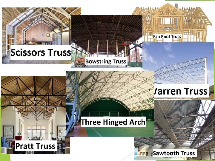
 • Trusses used to support roofs are selected based on the length the span, the slope, and the roof material • Scissors truss used for short spans that require overhead clearance. • Howe and Pratt trusses used for roofs of moderate span, about 18 m to 30 m • Fan truss or Fink or Cambered Fink truss For larger span roof • Warren truss For flat roof or nearly flat roof is to be selected, • Sawtooth trusses used when the building required an uniform lighting • Bowstring • Arched truss garages and small airplane hangars truss expensive, can be used for high rises and long spans such as field houses, gymnasiums
 Cables • Used to span long distance. • Cable usually flexible and carry their loads in tension. • Commonly used to support bridge and building roofs. • Because they are always in tension, cable will not become unstable and suddenly collapse as may happen in beams or trusses.
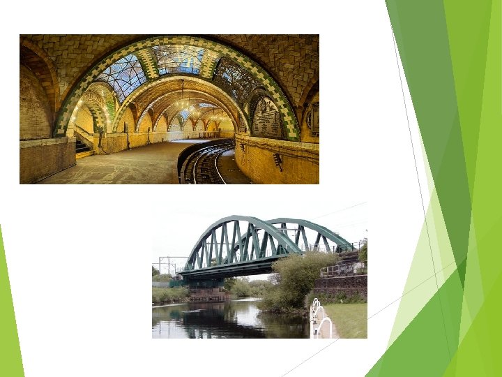
 Arches • • • Arch is a curved structure designed to carry loads across a gap mainly by compression and it has reverse curvature to that cable. The straight pieces of material joined by sharp bends are smoothed into a continuous curve. Arches must be rigid, however in order to maintain its shape, this result in secondary loading involving shear and moment. Usually used in bridge construction. This increases the cost of construction but greatly reduces the stresses.
 Frames • Frames are often used in building and are composed of beams and columns that are either pin or fixed connected • Like trusses, frames extend in two or three dimensions. • The loading on a frame causes bending of its members and if it has rigid joint connections, this structure is generally “indeterminate” from a standpoint of analysis. • The strength of a frame is derived from the moment interactions between the beams and the columns at the rigid joints
 Surface Structure • A surface structure is made from a material having a very small thickness compared to its other dimensions. • The structure is subjected to inplane(tension or compression forces mainly). • Surface structures may be made of rigid material such as reinforced concrete. • The structure may be shaped as folded plates, cylinders, etc. • They are referred to as thin plates or shells
 take 5…
 LOADS
LOADS
 Loads Design loading for a structure is often specified in codes General building codes specify the requirements of governmental bodies for minimum design loads on structures and minimum standards for construction Design codes - provide detailed technical standards and are used to establish the requirements for the actual structural design
 Permanent (Dead) loads Self-weight Weights of various structural members") Types of load Loads 1) Permanent (Dead) loads Self-weight Weights of various structural members Weights of any objects that are attached to the structure DL include the weights of the columns, beams, and girders, the floor slab, roofing, walls, windows, plumbing, electrical fixtures, and other miscellaneous attachments. In some cases, a structural dead load can be estimated satisfactorily from simple formulas based on the weights and sizes of similar structures.
Types of load Loads 1) Permanent (Dead) loads Self-weight Weights of various structural members Weights of any objects that are attached to the structure DL include the weights of the columns, beams, and girders, the floor slab, roofing, walls, windows, plumbing, electrical fixtures, and other miscellaneous attachments. In some cases, a structural dead load can be estimated satisfactorily from simple formulas based on the weights and sizes of similar structures.
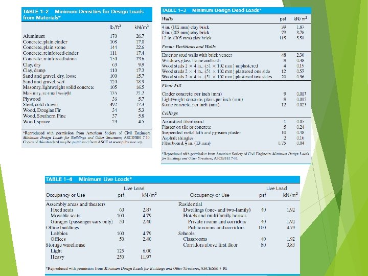
 Table 1– 2 shows the densities of typical materials used in construction and Table 1 -3 shows the weights of typical building components Normally, the dead load is not large compared to the design load for simple structures such as a beam or a single-story frame; however, for multistory buildings it is important to have an accurate accounting of all the dead loads in order to properly design the columns, especially for the lower floors.
 Example 1. 1 The floor beam is used to support the 1. 83 m width of lightweight plain concrete slab having a thickness of 102 mm. The slab serves as a portion of the ceiling for the floor below & its bottom coated with plaster. A 2. 44 m high, 305 mm thick lightweight solid concrete block wall is directly over the top flange of the beam. Determine the loading on the beam measured per m length of the beam.
 Example 1. 1 The floor beam is used to support the 1. 83 m width of lightweight plain concrete slab having a thickness of 102 mm. The slab serves as a portion of the ceiling for the floor below & its bottom coated with plaster. A 2. 44 m high, 305 mm thick lightweight solid concrete block wall is directly over the top flange of the beam. Determine the loading on the beam measured per m length of the beam.
 Live loads (Imposed loads) Varies in magnitude & location They may be") Loads 2) Live loads (Imposed loads) Varies in magnitude & location They may be caused by the weights of objects temporarily placed on a structure, moving vehicles, or natural forces. The minimum live loads specified in codes are determined from studying the history of their effects on existing structures. Usually, these loads include additional protection against excessive deflection or sudden overload
Loads 2) Live loads (Imposed loads) Varies in magnitude & location They may be caused by the weights of objects temporarily placed on a structure, moving vehicles, or natural forces. The minimum live loads specified in codes are determined from studying the history of their effects on existing structures. Usually, these loads include additional protection against excessive deflection or sudden overload
 Live loads - Building loads Depends on the purpose for which the building") 2(a) Live loads - Building loads Depends on the purpose for which the building is designed. Table 1– 4 shows a representative sample of such minimum live loadings, taken from the ASCE 7 -10 Standard. The values are determined from a history of loading various buildings. They include some protection against the possibility of overload due to emergency situations, construction loads, and serviceability requirements due to vibration.
2(a) Live loads - Building loads Depends on the purpose for which the building is designed. Table 1– 4 shows a representative sample of such minimum live loadings, taken from the ASCE 7 -10 Standard. The values are determined from a history of loading various buildings. They include some protection against the possibility of overload due to emergency situations, construction loads, and serviceability requirements due to vibration.
 For some types of buildings having very large floor areas, many codes will allow a reduction in the uniform live load for a floor. This reduced live load is calculated using the following equation: The reduced live load defined by Eq. 1– 1 is limited to not less than 50% of for members supporting one floor, or not less than 40% of for members supporting more than one floor.
 Live loads - Highway Bridge loads Primary live loads are those due to") 2(b) Live loads - Highway Bridge loads Primary live loads are those due to traffic and the heaviest vehicle loading encountered is that caused by a series of trucks Specifications for truck loadings are reported in AASHTO For 2 -axle truck, these loads are designated with H followed by the weight of truck in tons and another no. gives the year of the specifications that the load was reported 2 -axle truck with semi-trailer
2(b) Live loads - Highway Bridge loads Primary live loads are those due to traffic and the heaviest vehicle loading encountered is that caused by a series of trucks Specifications for truck loadings are reported in AASHTO For 2 -axle truck, these loads are designated with H followed by the weight of truck in tons and another no. gives the year of the specifications that the load was reported 2 -axle truck with semi-trailer
 Live loads - Railway Bridge loads Since train loadings involve a complicated series") 2(c) Live loads - Railway Bridge loads Since train loadings involve a complicated series of concentrated forces, to simply hand calculations, tables and graphs are sometimes used in conjunction with influence lines to obtain the critical load. The loading on railroad bridges are specified in the Specifications for Steel Railway Bridge published by the Amarican Railroad Engineers Association (AREA)
2(c) Live loads - Railway Bridge loads Since train loadings involve a complicated series of concentrated forces, to simply hand calculations, tables and graphs are sometimes used in conjunction with influence lines to obtain the critical load. The loading on railroad bridges are specified in the Specifications for Steel Railway Bridge published by the Amarican Railroad Engineers Association (AREA)
 Live loads – Impact loads Ø Moving vehicles may bounce or sidesway as") 2(d) Live loads – Impact loads Ø Moving vehicles may bounce or sidesway as they move over a bridge, and therefore they impart an impact to the deck. Ø The percentage increase of the live loads due to impact is called the impact factor, I.
2(d) Live loads – Impact loads Ø Moving vehicles may bounce or sidesway as they move over a bridge, and therefore they impart an impact to the deck. Ø The percentage increase of the live loads due to impact is called the impact factor, I.
 Live loads – Wind loads When the speed of the wind is very") 2(e) Live loads – Wind loads When the speed of the wind is very high, it can cause massive damage to a structure When structures block the flow of wind, the wind’s kinetic energy is converted into potential energy of pressure, which causes a wind loading. The effect of wind on a structure Depends on density & flow of air, angle of incidence, shape/stiffness of structure & roughness of surface
2(e) Live loads – Wind loads When the speed of the wind is very high, it can cause massive damage to a structure When structures block the flow of wind, the wind’s kinetic energy is converted into potential energy of pressure, which causes a wind loading. The effect of wind on a structure Depends on density & flow of air, angle of incidence, shape/stiffness of structure & roughness of surface

 Live loads – Earthquake loads Earthquake produce lateral loadings through its interaction with") 2(f) Live loads – Earthquake loads Earthquake produce lateral loadings through its interaction with the ground. Their magnitude depends on amount & type of ground acceleration, mass & stiffness of structure The figure shows the model that represent a single-story building, where the top block is the “lumped” mass of the roof, and the middle block is the lumped stiffness of all the building’s columns.
2(f) Live loads – Earthquake loads Earthquake produce lateral loadings through its interaction with the ground. Their magnitude depends on amount & type of ground acceleration, mass & stiffness of structure The figure shows the model that represent a single-story building, where the top block is the “lumped” mass of the roof, and the middle block is the lumped stiffness of all the building’s columns.

 Other Loads Hydrostatic & Soil Pressure When the structures are used to retain water or soil or granular materials, the pressure developed by these loadings becomes an important criterion for their design E. g. tanks, dams, ships, bulkheads & retaining walls Other natural loads Effect of blast Temperature Differential changes settlement of foundation
 Differential Settlement A common scenario is when a structure is built partially on undisturbed soil and partially on compacted fill. Soil in these two areas will consolidate at different rates as the weight of the newly-built structure forces water from between soil particles. This is called “differential settlement”.
 Structural Design Whenever a structure is designed, it is important to give consideration to both material and load uncertainties. Material uncertainties occur due to variability residual in material properties stress in materials intended measurements different from fabricated sizes material Many corrosion or decay types of loads can occur simultaneously on a structure
 Structural Design In working-stress design, the computed elastic stress in the material must not exceed the allowable stress along with the following typical load combinations as specified by the ASCE 7 -10 Standard Dead load 0. 6 (dead load) + wind load 0. 6 (dead load) + 0. 7(earthquake load)
 Structural Design Ultimate strength design is based on designing the ultimate strength of critical sections This method uses load factors to the loads or combination of loads 1. 4 (Dead load) 1. 2 (dead load) + 1. 6 (live load) + 0. 5 (snow load) 1. 2 (dead load) + 1. 5(earthquake load)+ 0. 5 (live load)
 Lets solve some tutorial questions….
 Problem 1 -1 The floor of a light storage warehouse building is made of 150 mm thick stone concrete. If the floor is a slab having a length of 3 m and width of 2. 4 m, determine the resultant force caused by the dead load and the live load.
 Problem 1 -2 The building wall consist of 200 mm clay brick. In the interior, the wall is made from 50 mm x 100 mm wood studs, plastered on one side. If the wall is 3 m high, determine the load in k. N per meter of length (k. N/m) of wall that the wall exert on the floor. Prob. 1– 2
 Problem 1 -3 The floor of the classroom building is made of 125 mm-thick lightweight concrete. If the office floor is a slab having a length of 8 m and width of 6 m, determine the resultant force caused by the dead load and the live load. Prob. 1– 3
 Problem 1 -4 The “New Jersey” barrier is commonly used during highway construction. Determine its weight per foot of length if it is made from plain stone concrete. 100 mm 300 mm 150 mm 600 mm
 Problem 1 -14 The double story office building has interior columns spaced 5 m apart in perpendicular directions. Determine the reduced live load supported by a typical interior column located on the first floor under the offices. Prob. 1– 14
 THANK YOU