3e3b4547ca9fbf740d66023f41dfe62e.ppt
- Количество слайдов: 32


CERTIFICATION AND APPROVAL SCHEME ABOUT DESIGN APPROVAL AND INSPECTION OF TANKS & INITIAL INSPECTION & MARKING TURKISH STANDARDS INSTITUTION DANGEROUS GOODS AND COMBINED TRANSPORTATION DIRECTORY 1 © 2013 Türk Standardları Enstitüsü
 2. Demountable tanks and 3. Battery-vehicles 4.")
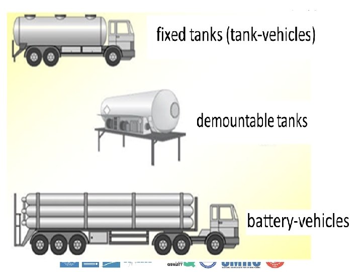
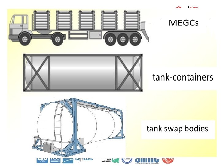
Types of Tanks 1. Fixed tanks (tank-vehicles) 2. Demountable tanks and 3. Battery-vehicles 4. Tank-containers 5. Tank swap bodies 6. MEGCs
, Demountable Tanks And Battery-vehicles Tank-containers, Tank Swap Bodies And")
General Requirements Fixed Tanks (Tank-vehicles), Demountable Tanks And Battery-vehicles Tank-containers, Tank Swap Bodies And MEGCs 1. The tanks and their fastenings shall be capable of absorbing, under the maximum permissible load, the forces exerted by: • in the direction of travel: twice the total mass • at right angles to the direction of travel the total mass • vertically upwards: the total mass • vertically downwards: twice the total mass. 1. Tank-containers and their fastenings shall, under the maximum permissible load be capable of absorbing the forces equal to those exerted by: • in the direction of travel: twice the total mass • horizontally at right angles to the direction of travel: the total mass; (where the direction of travel is not clearly determined, twice the total mass in each direction) • vertically upwards: the total
, Demountable Tanks And Battery-vehicles • Tank-containers, Tank Swap Bodies")
General Requirements Fixed Tanks (Tank-vehicles), Demountable Tanks And Battery-vehicles • Tank-containers, Tank Swap Bodies And MEGCs 2. Under each of these stresses the safety factors to be observed shall be the following: • for metals having a clearly-defined yield point: a safety factor of 1. 5 in relation to the apparent yield strength • for metals with no clearly-defined yield point: a safety factor of 1. 5 in relation to the guaranteed 0. 2% proof strength (1% maximum elongation for austenitic steels).

General Requirements Materials for shells 1. Shells shall be made of suitable metallic materials which, unless other temperature ranges are prescribed in the various classes, shall be resistant to brittle fracture and to stress corrosion cracking between -20 0 C and +50 0 C. 2. The materials of shells or of their protective linings which are in contact with the contents shall not contain substances liable to react dangerously with the contents, to form dangerous compounds, or substantially to weaken the material. 3. If contact between the substance carried and the material used for the construction of the shell entails a progressive decrease in the shell thickness, this thickness shall be increased at manufacture by an appropriate amount. This additional thickness to allow for corrosion shall not be taken into consideration in calculating the shell thickness.

General Requirements 4. For welded shells only materials of faultless weldability whose adequate impact strength at an ambient temperature of – 20 0 C can be guaranteed, particularly in the weld seams and the zones adjacent thereto, shall be used. 5. If fine-grained steel is used, the guaranteed value of the yield strength Re shall not exceed 460 N/mm 2 and the guaranteed value of the upper limit of tensile strength Rm shall not exceed 725 N/mm 2, in accordance with the specifications of the material. 6. Ratios of Re/Rm exceeding 0. 85 are not allowed for steels used in the construction of welded tanks. Ø Re = apparent yield strength for steels having a clearly-defined yield point or guaranteed 0. 2% proof strength for steels with no clearly-defined yield point (1% for austenitic steels) Ø Rm = tensile strength. Ø The values specified in the inspection certificate for the material shall be taken as a basis in determining this ratio in each case.

General Requirements 7. For steel, the elongation at fracture, in % shall be not less than 10000/determined tensile stenght in N/mm 2 Ø in any case for fine-grained steels it shall be not less than 16% and not less than 20% for other steels. Ø For aluminium alloys the elongation at fracture shall be not less than 12%.

General Requirements Calculation of the shell thickness Ø The calculation pressure is in the second part of the tank code When "G" appears, the following requirements shall apply: – Gravity-discharge shells intended for the carriage of substances having a vapour pressure not exceeding 110 k. Pa (1. 1 bar) (absolute pressure) at 50 ºC shall be designed for a calculation pressure of twice the static pressure of the substance to be carried but not less than twice the static pressure of water – Pressure-filled or pressure-discharge shells intended for the carriage of substances having a vapour pressure not exceeding 110 k. Pa (1. 1 bar) (absolute pressure) at 50 ºC shall be designed for a calculation pressure equal to 1. 3 times the filling or discharge pressure When the numerical value of the minimum calculation pressure is given (gauge pressure) the shell shall be designed for this pressure which shall not be less than 1. 3 times the filling or discharge pressure. The following minimum requirements shall apply in these cases: – Shells intended for the carriage of substances having a vapour pressure of more than 110 k. Pa (1. 1 bar) at 50 °C and a boiling point of more than 35 °C shall, whatever their filling or discharge system, be designed for a calculation pressure of not less than 150 k. Pa (1. 5 bar) gauge pressure or 1. 3 times the filling or discharge pressure, whichever is the higher – Shells intended for the carriage of substances having a boiling point of not more
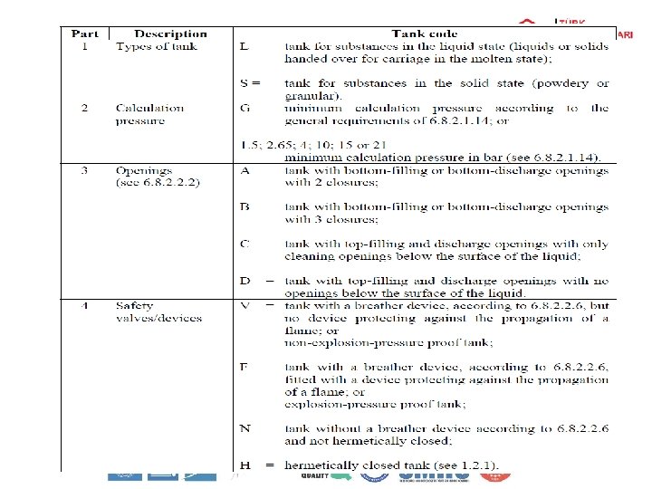

Hierarchy of tanks Part 1: Types of tanks S L Part 2: Calculation pressure 15 21 bar G 1. 5 2. 65 4 10 Part 3: Openings A B C D Part 4: Safety valves/devices V F N H For example: - A tank with the tank code L 10 CN is authorized for the carriage of a substance to which the tank code L 4 BN has been assigned; - A tank with the tank code L 4 BN is authorized for the carriage of a substance to which the tank code SGAN has been assigned.

General Requirements

General Requirements Shells of circular cross-section not more than 1. 80 m in diameter (mm) Shells of circular cross-section more than 1. 80 m in diameter (not in the case of shells intended for the carriage of powdery or granular substances) (mm) Mild steel (steel with a tensile strength of 370 N/mm 2 and an elongation after fracture of 27 %) 5 6 Where protection of the tank against damage through lateral impact or overturning is provided Mild steel 3 4 Austenitic stainless steels 2, 5 3 Austenitic-ferritic stainless steels 3 3, 5 Other steels 3 4 Pure aluminium of 99. 80% 6 8 Aluminium alloys 4 5

General Requirements Welding and inspection of welds ü The manufacturer's qualification for performing welding operations shall be one recognized by the competent authority. Welding shall be performed by skilled welders using a welding process whose effectiveness (including any heat treatments required) has been demonstrated by test. Non-destructive tests shall be carried out by radiography or by ultrasound and must confirm that the quality of the welding is appropriate to the stresses. ü The following checks shall be carried out in accordance with the value of the coefficient λ used in determining the thickness of the shell λ = 0. 8: the weld beads shall so far as possible be inspected visually on both faces and shall be subjected to a non-destructive spot check. All weld "Tee» junctions with the total length of weld examined to be not less than 10% of the sum of the length of all longitudinal, circumferential and radial (in the tank ends) welds shall be tested; λ= 0. 9: all longitudinal beads throughout their length, all connections, 25% of circular beads, and welds for the assembly of large-diameter items of equipment shall be subjected to non-destructive checks. Beads shall be checked visually on both sides as far as possible;

Inspections

Inspections • Shells and their equipment shall undergo periodic inspections no later than every Six years Five years • Shells and their equipment shall undergo intermediate inspections at least every Three years Two and a half years

Examination of Documents Type Approval ü name and address of the applicant ü description of the tank prototype including planned variations to the design and its special characteristics ü names and addresses of the manufacturer and the assembler of the tank; in the case of fixed tanks (tank vehicles) or rail tank wagons the design of chassis or wagon; in the case of tank containers or portable tanks the manufacturer and design of frame if applicable ü certificate of welder and welding procedure qualification in accordance with the technical code; when the technical code does not contain requirements for qualification of the welder and welding procedure the requirements of EN 287 -1, EN ISO 9606 -2, EN ISO 9606 -3, EN ISO 9606 -4, EN ISO 15607, EN ISO 15609 -1, EN ISO 15614 -1 shall be met as applicable ü description of the assigned mode of operation (e. g. pressure discharging) ü indication of the portable tank instruction, or tank code and the applicable special provisions TA (type approval), TC (construction) and TE (equipment) ü if required, listing of all substances or groups of substances to be carried by the tank (especially for substances of class 2 and special substances listed in the regulation for which additional requirements can apply) ü schematic drawing of the tank with listing of main dimensions ü schematic drawings of the piping systems ü data sheet with the operational data of the tank necessary for calculation

Examination of Documents ü calculation and, if required, verification by testing of the tank and its fastenings ü drawings necessary for verifying the manufacture of the tank, of its equipment and of its fastenings, including an assembly drawing and a parts list indicating the materials drawings for marking (tank plates and others) listing of the service equipment with the relevant technical data ü suitability of the safety equipment including the calculation of the relief capacity if relevant ü material test certificates as required by the applied technical code for the base materials used for tank and structural equipment showing values of material properties as required by the relevant regulation ü material identification of welding filler materials ü proof of material grades used for the service equipment ü record of tests carried out on production control test plates (the test plates shall be inspected by the inspector) if required by the technical code and/or the relevant regulations concerning the transport of dangerous goods ü when using a protective lining or coating, proof that the protective lining or coating has been applied in accordance with the manufacturer's specification record of non-destructive testing carried out on the welds ü qualification certificate for personnel undertaking non-destructive test (NDT) ü if relevant, validation of the NDT technique used

Examination of Documents Initial Inspection ü ü ü ü application for initial inspection type approval certificate information given in the application of type approval where necessary certificate of welder and welding procedure qualification in accordance with the technical code; when the technical code does not contain requirements for qualification of the welder and welding procedure the requirements of EN 2871, EN ISO 9606 -2, EN ISO 9606 -3, EN ISO 9606 -4, EN ISO 15607, EN ISO 15609 -1, EN ISO 15614 -1 shall be met as applicable material test certificates as required by the applied technical code for the base materials used for tank and structural equipment showing values of material properties material identification of welding filler materials proof of material grades used for the service equipment record of tests carried out on production control test plates (the test plates shall be inspected by the inspector) if required by the technical code and/or the relevant regulations concerning the transport of dangerous goods when using a protective lining or coating, proof that the protective lining or coating has been applied in accordance with the manufacturer's specification record of non destructive testing carried out on the welds qualification certificate for personnel undertaking non-destructive test (NDT) heat treatment procedure and records of heat treatment calculation of water capacity, if applicable

Examination of Documents Periodic and Intermadiate Inspection ü certificate of initial inspection if the tank has not been subject to periodic inspection ü certificate of last periodic inspection, if applicable ü certificate of intermediate inspection if carried out after the previous periodic inspection or after the initial inspection if there has been no periodic inspection ü if required one or more of the documents mentioned above

Check of The Design Characteristics ü examination of the manufacturing conditions ü inspection of the material grades and wall thicknesses ü examination of the manufacturing methods ü inspection of the condition of the tank ü inspection of the main dimensions ü non-destructive testing of the welds ü testing of test plates (where required by regulation or relevant technical code)

Inspection of The Tank Interior ü A complete visual inspection shall be performed (provided no protective lining or coating is used) to identify any surface defect. ü The wall thickness shall be verified against that given by the type approval documents by appropriate measurement if the tank shows indication of reduction of wall thickness. ü Any lining or coating not falling under the definition of protective lining or coating given in this document shall be visually inspected for integrity. In particular bonding defects or delaminations shall be identified and recorded in the report. ü The condition of the protective lining or coating shall be inspected by appropriate methods, e. g. spark test, and in accordance with the manufacturer's recommendations. In particular bonding defects shall be identified and recorded in the report.

Inspection of The Tank Exterior ü A complete visual inspection shall be performed to identify any surface defect. ü The wall thickness shall be verified against that given by the type approval documents by appropriate measurement if the tank shows indication of reduction of wall thickness. ü Sheathing, thermal or other insulation shall be removed only to the extent required to achieve a reliable appraisal of the condition of the tank.

Inspection of The Tank Exterior Inspection of the fastenings of the tank and its structural equipment ü The following elements shall be inspected by an appropriate method to ensure that they are in good condition: – structures supporting and reinforcing the tank – means of attachment to the frame or chassis – any structural protective equipment e. g. the cover assembly, the sun shield. ü Sheathing, thermal or other insulation shall be removed only to the extent required to achieve a reliable appraisal.

Inspection of The Tank Exterior Inspection of earthing terminal ü Shells which are required to be fitted with an earth connection shall be inspected for conformity of the earth connection with the design requirements. The electrical resistance between the earth connection and the metallic parts of the tank and equipment, including any frame and where applicable between the earth connection and the vehicle chassis, shall not exceed 10 Ω.

Hydrolic Pressure. Test • Test Pressure: • Test Duration: The test pressure shall be held for the time necessary for the inspector to carry out the inspection of the shell or a compartment but not less than 15 min for a non-insulated tank and not less than 30 min for an insulated tank. • Test fluid: The fluid normally used for testing shall be water. ØOther liquids may be used with agreement of the inspector. The flash point of alternative test liquids shall be above 61 °C. Toxic or corrosive liquids shall not be used. ØGases may be used for pressure testing only in special cases and with agreement of the inspector. Flammable or toxic gases shall not be used.

Hydrolic Pressure. Test ØThe tank fails the hydraulic pressure test if any of the following occur: Ø a leak is detected; Øthere is an unaccountable fall in pressure during the test period; Ø there is visible permanent deformation.

Vacuum testing • Test procedure The tank shall start the test empty and at atmospheric pressure. All openings of the tank shall be closed except the discharge openings. A pressure of 1, 5 times more severe than the external design pressure shall be created inside the tank and held for 5 min. • Measurement The accuracy of the measuring equipment shall be equal to or less than 1 % of full scale deflection; this accuracy shall be attested by a calibration certificate. For selection and installation of pressure gauges EN 837 -2 shall be used. • Evaluation of the test The tank fails the test if any of the following occur: – a leak is detected; – there is an unaccountable rise of pressure at the pressure gauge; – there is visible permanent deformation.

Leakproofness test • Test Pressure: – The leakproofness test shall be carried out with the pressure given by the relevant regulation. – The test pressure shall be related to the highest point of the tank or compartment. If there is no specific regulation, a pressure of not less than 25 % of the maximum working pressure with a minimum of 0, 2 bar shall be applied. – The leakproofness test for refrigerated liquefied gases shall be carried out with a pressure of not less than 90 % of the maximum working pressure. – Internal leakproofness of shut-off devices shall be tested at the leakproofness test pressure as well as at a pressure of not more than 0, 2 bar. • Test fluid: – The test fluid shall be compatible with the materials of the tank and the goods to be transported. – The test fluid shall in no case create a hazard to the inspecting personnel or any other persons in the vicinity. • Test Duration: – The test pressure shall be held for the time necessary for the inspector to carry out the inspection of the shell, a compartment or the equipment but not less than 5 min in each case. • Evaluation of the test

Marking

Marking
3e3b4547ca9fbf740d66023f41dfe62e.ppt