

cffc20dc50ee88e14e708db33954f003.ppt
- Количество слайдов: 53
 CE 3372 WATER SYSTEMS DESIGN Lecture 06 – Pumps and Lift Stations
 Overview Review of EPA-NET lecture Valves Pumps Suction Requirements System and Pump Curves Lift Stations
 Review The Project Game 1 st Place: +5% 2 nd Place: +4% 3 rd Place: +3% What is EPA-NET? How many Reservoirs? User Manual? Three main comp. to run EPA-NET?
 Valves
 Valves Devices which control amount and direction of fluid flow in closed conduit systems Bronze, brass, iron, or steel alloy
 Types of Valves Stop Valves – Used to completely/partially shut off flow of fluid (ex: Check Valves – Used to permit flow in only one direction (ex: globe, butterfly, gate, plug, needle) ball-check, swing-check, lift-check) Special Valves relief, pressure-reducing, remote-operated
 Globe Valve
 Gate Valve
 Butterfly Valve
 Swing-check Valve
 Pumps
Pumps
 Pumps A mechanical device that uses suction or pressure to to raise or move fluid lower to higher elevation
 Pumps Positive Displacement Pumps Fixed volume of fluid is displaced each cycle regardless of static head/pressure Lower flow rates and higher head than non-positive pumps Non-Positive Displacement Pumps (Centrifugal etc. Pumps) Volume of fluid is dependent on static head/pressure
 Pumps") Pumps Positive Displacement Pumps Screw Pumps Reciprocating Pumps Non-Positive Displacement Pumps Centrifugal (Radial-Flow) Pumps Propeller Pumps (Axial-Flow) Jet Pumps (Mixed-Flow)
Pumps Positive Displacement Pumps Screw Pumps Reciprocating Pumps Non-Positive Displacement Pumps Centrifugal (Radial-Flow) Pumps Propeller Pumps (Axial-Flow) Jet Pumps (Mixed-Flow)
 Positive Displacement Pumps Screw Pump A revolving shaft with blades rotates in a trough at an incline and pushes water up
 Positive Displacement Pumps Reciprocating Pump A piston sucks the fluid into a cylinder and then pushes it out
 Pumps") Pumps Positive Displacement Pumps Screw Pumps Reciprocating Pumps Non-Positive Displacement Pumps Centrifugal (Radial-Flow) Pumps Propeller Pumps (Axial-Flow) Jet Pumps (Mixed-Flow)
Pumps Positive Displacement Pumps Screw Pumps Reciprocating Pumps Non-Positive Displacement Pumps Centrifugal (Radial-Flow) Pumps Propeller Pumps (Axial-Flow) Jet Pumps (Mixed-Flow)
 Non-Positive Displacement Pumps Classification is based on the way water leaves the rotating part of the pump Radial-flow pump – water leaves impeller in radial direction Axial-flow pump – water leaves propeller in the axial direction Mixed-flow pump – water leaves impeller in an inclined direction (has both radial and axial components)
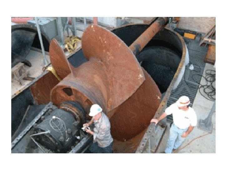
 Radial-Flow Pumps Centrifugal Pump Accelerates water using an impeller Video Explanation Cool Video Discharge Suct ion ( Eye)
 Axial Flow Pumps Axial flow pumps have impellers whose axis of rotation is collinear with the discharge Used in high flow, low head applications discharge suction
 Suction Requirements
 Suction Requirements The most common cause of pumping failure is poor suction conditions Cavitation occurs when liquid pressure is reduced to the vapor pressure of the liquid For piping system with a pump, cavitation occurs when Pabs at the inflow falls below the vapor pressure of the water
 Suction Requirements Liquid must enter the pump eye under pressure; this pressure is called the Net Positive Suction Head available (NPSHa). A centrifugal pump cannot lift water unless it is primed the first stage impellers must be located below the static HGL in the suction pit at pump start-up
 Suction Requirements The manufacturer supplies a value for the minimum pressure the pump needs to operate. This pressure is the Net Positive Suction Head required (NPSHr). For proper pump operation (w/o cavitation) NPSHa> NPSHr
 Suction Requirements Available suction is computed from Frictional head loss in inlet piping Absolute pressure at liquid surface in suction pit Static elevation of the liquid above the pump inlet eye Absolute vapor pressure at liquid pumping temperature
 Suction Requirements Example
 Suction Requirements Example
 Suction Requirements Example
 Suction Requirements Example
 Suction Requirements Example
 System and Pump Curves
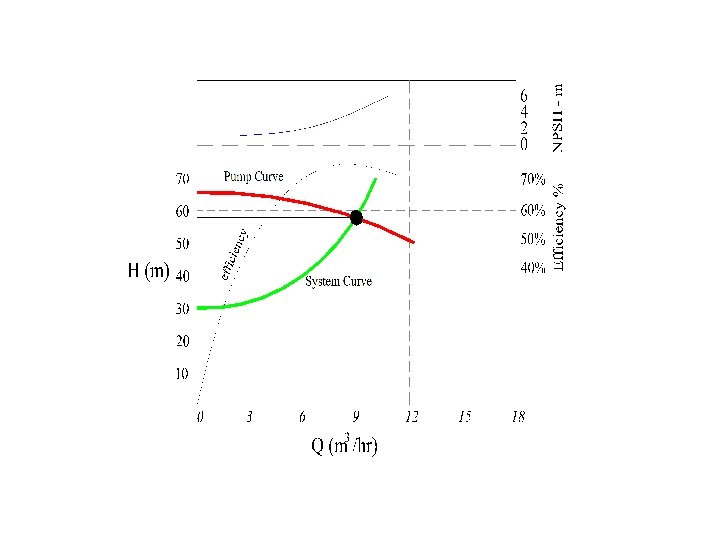
 Selecting Pumps Design conditions are specified Pump is selected for the range of applications A System Curve (H vs. Q) is prepared System Curve is matched to Pump Curve Matching point (Operating point) indicates the actual working conditions
 curve is a plot of required head versus flow") System Curves A system (characteristic) curve is a plot of required head versus flow rate in a hydraulic system (H vs. Q) The curve depicts how much energy is necessary to maintain a steady flow under the supplied conditions Total head, Hp, = elevation head + head losses
System Curves A system (characteristic) curve is a plot of required head versus flow rate in a hydraulic system (H vs. Q) The curve depicts how much energy is necessary to maintain a steady flow under the supplied conditions Total head, Hp, = elevation head + head losses
 System Curves
 System Curves This relationship tells us that the added head has to be at least 30 meters just to keep the reservoirs at the two levels shown, if any flow is to occur the pump must supply at least 30+meters of head.
 Pump Curves Provided information from the manufacturer on the performance of pumps in the form of curves. Information may include: discharge on the x-axis head on the left y-axis pump power input on the right y-axis pump efficiency as a percentage speed of the pump (rpm) NPSH of the pump
 Pump Curves Provided d.
 How to Provided information from the manufacturer on the performance of pumps in the form of curves. Information may include: discharge on the x-axis head on the left y-axis pump power input on the right y-axis pump efficiency as a percentage speed of the pump (rpm) NPSH of the pump
 Pump Curves Operating Point Pump A cannot meet the needs of the system at any flow rate Pump B supplies enough head over part of the system curve The shaded area is the area where the pump supplies excess head
 Multiple Pumps Series and parallel combinations can be used to adjust “pump curves” to fit system requirements. Parallel pumps add flow for given head Series pumps add head for given flow
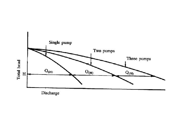
 H 3 H 1 2 H 1 H 1 Three pumps in series Two pumps in series Single pump H 1 Q Q 1
 Pumps in EPA-NET Pumps are modeled as links between two nodes that have pumping curve properties. Each node must have appropriate elevations. A pump is added as a link, then the pump curve is specified for that pump. The program will operate the pump out-of-range but issue warnings to guide the analyst to errors.
 Lift Stations!
 Lift Stations Lift wastewater/stormwater to higher elevations when: discharge of local collection system lies below regional conveyance terrain or man-made obstacles do not permit gravity flow to discharge point.
 Pond and Pump Station
 Types of Lift Stations Submersible Lower initial cost Lower capacity Smaller footprint Wet-well / dry-well Higher initial cost Easier inspection/ maintenance
 Submersible lift station
 Wet-well / dry-well lift station
 storage capacity to accommodate inflow") Design criteria Size the pumps and the wet-well (sump) storage capacity to accommodate inflow variability and detention time limits. Match the pumps to the flow and head requirements. Provide ‘near-absolute’ reliability Automated controls Redundant systems Alarms Regularly scheduled, preventive maintenance Assess and mitigate environmental factors Flood risk, noise pollution, visibility
Design criteria Size the pumps and the wet-well (sump) storage capacity to accommodate inflow variability and detention time limits. Match the pumps to the flow and head requirements. Provide ‘near-absolute’ reliability Automated controls Redundant systems Alarms Regularly scheduled, preventive maintenance Assess and mitigate environmental factors Flood risk, noise pollution, visibility
 Site plan and facilities Protected and accessible during a major flood Redundant power supplies Intruder-resistant with controlled access