f4f0915a08b670621e712bf72d473dd1.ppt
- Количество слайдов: 67


BASICS OF PNEUMATICS

Composition of air Air is composed mainly of nitrogen and oxygen Composition by Volume Nitrogen 78. 09% N 2 Oxygen 20. 95% O 2 Argon 0. 93% Ar Others 0. 03%

Pressure is defined as force acting per unit area l For measurements in pounds per square inch (psi) 14. 5 psi = 1 bar l 1 bar = 100000 N/m 2 (Newtons per square metre) 1 bar = 10 N/cm 2

When we are applying force to the normal air, it will get compressed Normally in industrial application the range of pressure will be 6 – 10 bar For special application like testing and in submarine application high pressure is used. Absolute pressure bar a 17 16 15 14 13 12 11 10 9 8 7 6 5 4 3 2 1 0 Gauge pressure bar g Compressed air 16 15 14 13 12 11 10 9 8 7 6 5 4 3 2 1 0 Extended Industrial range Typical Industrial range Low range Atmosphere Full vacuum

Pressure units There are many units of pressure measurement. Some of these and their equivalents are listed below. 1 bar = 100000 N/m 2 1 bar = 100 k. Pa 1 bar = 14. 50 psi 1 bar = 10197 kgf/m 2 1 mm Hg = 1. 334 mbar 1 mm H 2 O = 0. 0979 mbar More units of pressure

Flow units Flow is measured as a volume of free air per unit of time Popular units are : 1 cubic foot 1 litre or cubic decimetre Litres or cubic metres per second l/s or m 3/s 1000 m 3/s = 1 l/s 1 cubic metre or 1000 dm 3

APPLICATION OF PNEUMATIC SYSTEM MINING AND CONSTRUCTION INDUSTRY. BOTTLING INDUSTRY. ROLLING MILLS & FOUNDRIES. AUTOMOTIVE INDUSTRIES. INDUSTRIAL AUTOMATION. MACHINE TOOLS. HAND TOOLS. OTHERS.

TYPES OF COMPRESSORS COMPRESSO RS POSITIVE DISPLACEME NT RECIPROCAT ING SCREW DYNAMIC TWIN LOBE CENTRIFUGA L ROTARY AXIAL

RECIPROCATING COMPRESSOR

As the piston descends, increasing the available space, the decrease in pressure causes the inlet valve to open and air to be drawn into the compressor chamber. Subsequently, after the piston has passed its turning point corresponding to the maximum volume of the compressor chamber, the inlet valve closes as the air pressure starts to increase. As the volume of the compression chamber decreases, the air pressure increases. Finally, when the pressure has reached a predetermined value, the discharge valve opens, and the compressed air leave the compression chamber.

RECIPROCATING AIR COMPRESSOR RECIPROCATING COMPRESSOR CONSIST OF FOLLOWING MAIN PARTS 1. MOTOR 4. PISTON. 6. INLET VALVE 10. AIR RESEVOIR. 2. CRANK. 5. PISTON RINGS. 8. EXHAUST VALVE 3. PISTON ROD 9. NON RETURN VALVE. 11. SAFETY VALVE. 6. FILTER

RECIPROCATING AIR COMPRESSOR MOTOR WILL DRIVE THE CRANK BY PULLEY. CRANK WILL ROTATE AND MOVE THE PISTON ROD TO UP AND DOWN. WHILE MOVING DOWN, PISTON CONNECTED TO PISTON ROD SUCKS THE AIR THROUGH INLET VALVE. AGAIN DUE TO CRANK ROTATION PISTON MOVES UP AND COMPRESS THE AIR. THE COMPRESSED AIR MOVES THE EXHAUST VALVE UP AND ESCAPES. PISTON RINGS ARE PROVIDED AROUND PISTON INORDER TO SEAL THE COMPRESSED AIR AND LUBRICATE THE CYLINDER. SUCTION FILTER IS PROVIDED IN ORDER TO ALLOW CLEAN AIR TO CYLINDER. NON RETURN VALVE IS PROVIDED INORDER TO PREVENT THE REVERSE FLOW OF COMPRESSED AIR. THE COMPRESSED AIR WILL GET FILLED IN THE AIR RESERVOIR UNIT. AIR RESERVIOR UNIT IS PROVIDED IN ORDER TO SUPPLY CONSTANT FLOW OF AIR TO THE LINE. A SAFETY VALVE (PRESSURE RELIEF VALVE) IS PROVIDED IN THE RESERVOIR FOR SAFETY PURPOSE.

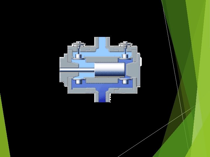
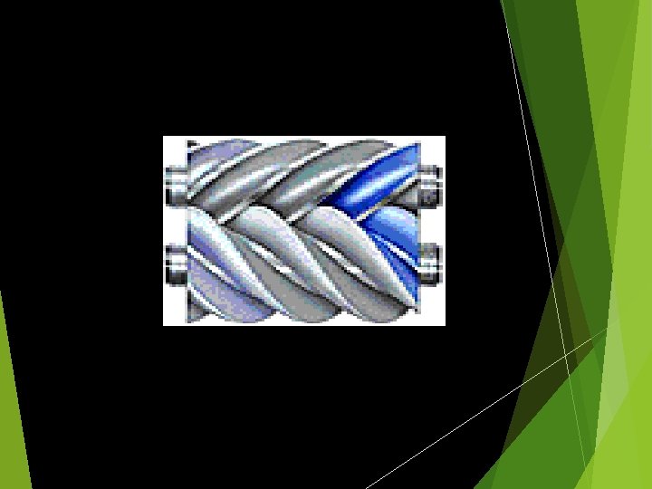
SCREW COMPRESSOR

Screw compressor consists of two rotors, one male rotor and one female rotor. The male rotor has four equally spaced helical lobes. The rotors used have asymmetrical rotor profiles. This type of profile allows the female rotor to be driven directly by the male rotor, avoiding the need for synchronizing gearwheels. Because the rotary screw compressor uses the positive displacement principle, the air delivery is directly proportional to the rotation speed. The higher the speed, the larger the volume displaced by the compressor element 1 - The ends of the rotors uncover the inlet and air enters the compression chamber. 2 - The air is entrapped in the 'compartment' formed by a male lobe and a female flute. 3 - As the rotors turn, the compartment becomes progressively smaller, thereby compressing the entrapped air. 4 - Compressed air leaves through the outlet port

Intake air. Air/Oil mixture Wet Air. Refrigerant. Oil Air flow : 1. Air intake filter - 2. Air intake valve - 3. Compression element - 4. Non-return valve - 5. Oil separator element 6. Minimum pressure valve - 7. After cooler - 8. Air to air heat exchanger - 9. Water separator with drain- 10. Filter (optional) Oil flow : 11. Oil reservoir - 12. Oil cooler - 13. Thermostatic bypass valve - 14. Oil filter - 15. Oil stop valve – Refrigeration flow : 16. Refrigerant compressor - 17. Condenser - 18. Liquid refrigerant dryer/filter - 19. Capillary tube 20. Evaporator - 21. Hot gas bypass valve - 22. Accumulator

PRECAUTION IN HANDLING THE COMPRESSORS BEFORE OPENING ANY PARTS INSIDE THE COMPRESSOR UNLOAD ALL THE PRESSURISED AIR AND ENSURE NO PRESSURE INSIDE COMPRESSOR. NEVER TOUCH THE LIVE WIRE INSIDE THE COMPRESSOR. BEFORE OPENING THE INSIDE PARTS OF COMPRESSOR NEVER FORGET TO CLOSE THE OUTLET VALVE. TEMPERATURE OF THE COMPRESSED OIL IS MORE. SO BEFORE CHANGING THE OIL ALLOW IT TO COOL. NEVER ADJUST THE SAFETY VALVE SETTING. DON’T CHANGE THE PARAMETER SETTING UNTIL OTHERWISE IT IS VERY MUCH ESSENTIAL.

NEVER ALLOW AIR LEAKAGE ANYWHERE A SMALL CALCULATION ON AIR LEAKAGE. CONSIDER OUR BIG COMPRESSOR (NO 1) IS RUNNING. CAPACITY OF COMPRESSOR - 75 KW. VOLUME PRODUCED BY COMPRESSOR - 500 CFM. CONSIDER IF AIR IS LEAKING FROM ¼”BSP PIPE. VOLUME OF AIR LEAKING AT 6 BAR PRESSURE - 94 CFM. FOR PRODUCING 500 CFM IT NEEDED 75 KW. TO PRODUCE 94 CFM IT REQUIRE AROUND 14. 25 KW/HR FOR ONE YEAR SAY COMPRESSOR IS LOADED FOR 3000 HRS. SO IT CONSUME 14. 25 X 3000 = 42, 750 UNITS YEARLY. NEARLY 2. 5 LACS + EXTRA COST IS LOST FOR COMPANY. SO NEVER ALLOW AIR LEAKAGE IN COMPANY.


PRESSURE REGULATOR DIRECTION CONTROL VALVE AND SILENCER FILTER – REGULATOR- LUBRICATOR FLOW CONTROL VALVE

FRL’s FRL stands for filter, regulator and lubricator When an FRL unit is referred to, it means a combination of these three devices closely connected together They form a unit that will prepare the condition of compressed air just before delivering it to pneumatic equipment or machinery This ensures the air supply is clean and dry, the pressure is at the correct level and fine particles of oil are carried in the air to lubricate the wearing parts within valves, cylinders and tools A convenient method of combining these components is to use a modular system
 l SYMBOL LOUVER l l FILTER l WATER PARTICLES DRAIN PLUG")
Filter (general principle) l SYMBOL LOUVER l l FILTER l WATER PARTICLES DRAIN PLUG l Separate and collect contaminants Angled louvers spin the air as it enters the bowl Water droplets and large solid particles spun outwards against bowl and run to the bottom Baffle prevents turbulent air splashing water on to the filter element Element traps finer solid particles

Compressed air quality ISO 8573 -1 Class Water Oil particle concentration size maximum µm mg/m 3 1 2 3 4 5 6 7 Solids Max Pressure Dew point OC concentration mg/m 3 – 70 – 40 – 20 0. 01 0. 1 1 5 25 - 0. 1 1 5 15 40 - 0. 1 1 5 8 10 - +3 +7 + 10 Not Specified Pressure dew point is the temperature to which compressed air must be cooled before water vapour in the air starts to condense into water particles

Pressure regulator 4 2 6 40 80 120 lbf/in 2 bar 8 10 P 1 P 2 This is a relieving regulator to allow pressure to be reduced to a lower setting Turn anticlockwise to reduce the spring force The higher force under the diaphragm lifts it clear of the valve spindle P 2 can now exhaust until the diaphragm seals Turn clockwise to adjust up to the new pressure

Pressure regulator 2 Flow demand will open the poppet valve wide enough to satisfy the flow rate at pressure P 2 can be set on a gauge fitted to the regulator 6 40 80 120 lbf/in 2 bar P 1 When there is no flow demand the poppet valve closes to hold the pressure at P 2 4 Reduces supply pressure P 1 to a suitable working pressure P 2 8 10

Pressure regulator 80 40 120 lbf/in 2 bar P 1 P 2 8 Turn clockwise until new P 2 pressure reached The higher spring force pushes the valve open 2 6 4 To increase pressure P 2, pull the adjusting knob up to disengage the locking teeth The rising pressure P 2 acts under the diaphragm to balance the spring and allow the valve to close 10

Filter Regulator l l l Filter and regulator designed as a single unit Air is first filtered then directed to the primary side of the regulator Pressure is then reduced to a working value Only one unit to install Cost saving when compared to two separate units

Lubrication Been for efficient running of pneumatic equipment and long life of seals and wearing surfaces, correct lubrication is essential For the best results light lubrication is applied continuously from an air line lubricator. This is particularly relevant in adverse applications where there may be high speed and high temperature running or where the condition of the compressed air has poor In a lubricator, oil drips are atomised and the tiny oil particles form a very fine mist in the air supplying the application

Lubricator Unit Oil is sucked in yellow tube by its pressure difference. Its flow will be controlled by green knob at top side. P 2 P 1 P 2 Oil will drip as droplet and it will become small droplet and mixes at delivery air. Normally recommended oil is VG 32. P 1

Valve Types Function is the switching complexity of a valve Shown by two figures 2/2, 3/2, 4/2, 5/2, 3/3, 4/3 & 5/3 First figure is the number of main ports. Inlets, outlets, and exhausts excluding signal and external pilot supplies Second figure is the number of states A 3/2 valve has 3 ports, and 2 states, normal and operated.

DIRECTION CONTROL VALVE

Valve Size refers to a valve’s port thread. For similarly designed valves the amount of air flow through the valve usually increases with the port size. Port size alone however cannot be relied upon to give a standard value of flow as this is dependent on the design of the valve internals. M 5 The port size progression M 5, R 1/8 , R 1/4, R 3 / 8 , R 1 / 2 , R 3/4, R 1. R 3 / 8 R 1 / 2 R 1 / 4 R 1 R 3 / 4
 2 12 3 1 10 2 12 3 10 1")
Actuator Control (3/2 valve) 2 12 3 1 10 2 12 3 10 1 A 3 port valve provides the inlet, outlet and exhaust path and is the normal choice for control of a single acting cylinder In the normal position produced by the spring, the valve is closed In the operated position produced by the push button the valve is open The push button must be held down for as long as the cylinder is
 4 4 2 14 12 5 1 3 A five")
Actuator Control (5/2 valve) 4 4 2 14 12 5 1 3 A five port valve provides an inlet port 1 that is switched between two outlet ports 2 and 4 each with an exhaust port 3 & 5 In the normal position produced by the spring 1 is connected to 2 with 4 to exhaust 5 In the operated position produced by pushing the button port 1 is connected to 4 with 2 to exhaust
 With the spool in the mid (normal) position the supply")
5/3 Valve (open exhausts) With the spool in the mid (normal) position the supply port is sealed and outlet ports are to exhaust Spool right, port 1 is joined to 4, port 2 is joined to 3 Spool left, port 1 is joined to 2, port 4 is joined to 5 4 2 5 1 3 14 12 5 4 1 2 3

Typical Valve Identification of the component parts of a typical 5/2 solenoid valve with spring return Pressure indicator Manual override Electric connectors 9 Alternative ports 2, 4 Return spring SOLENOID PISTON Valve body Spool with disc seals

Pilot operated 2/2 seat valve Springs provide excellent sealing in the normally closed position Air pilot signal lifts the seat against the spring AIR PILOT In sizes G 1/2 to G 2 for high flow SPOOL WILL LIFT WHEN AIR Suitable for vacuum to up to ENTERD IN TO PILOT 16 bar Can be close connected with a solenoid pilot valve to generate the pilot signal INLET Click the illustration to start and stop animation

Flow Regulation By the use of flow regulators the outstroke speed and instroke speed of a piston rod can be independently adjusted Speed is regulated by controlling the flow of air to exhaust The front port regulator controls the outstroke speed and the rear port regulator controls the instroke speed

Flow regulator Uni-directional, line mounted adjustable flow regulator Free flow in one direction Adjustable restricted flow in the other direction

Banjo Flow Regulator Designed to fit directly in to cylinder ports, so placing adjustment at the appropriate cylinder end Two types: One to give conventional flow restriction out of the cylinder and free flow in (as illustrated) The other type to give restricted flow in to the cylinder and free flow out (not illustrated)

Guide to Valve Size and Flow This graph gives a guide to the to flow range appropriate to different valve sizes Port size alone can only be a rough guide, individual valve types will vary according to design The flow values indicated by the vertical lines are at P 1 = 6 bar, with 1 bar pressure drop R 1 R 3/4 1 Valve R /2 3 size R /8 R 1/4 R 1/8 M 5 250 1250 750 2500 4250 6000 Flow l/min 10000

Introduction To Actuators Pneumatic actuators include linear cylinders and rotary actuators. They are devices providing power and motion to automated systems, machines and processes. A pneumatic cylinder is a simple, low cost, easy to install device that is ideal for producing powerful linear movement. Speed can be adjusted over a wide range. A cylinder can be stalled without damage.

Introduction To Actuators Adverse conditions can be easily tolerated such as high humidity, dry and dusty environments and cleaning down with a hose. The bore of a cylinder determines the maximum force that it can exert. The stroke of a cylinder determines the maximum linear movement that it can produce. The maximum working pressure depends on the cylinder design. VDMA cylinders work up to 16 bar. Thrust is controllable through a pressure regulator.

Basic Construction seal cushion 1 cushion seal 2 magnet 3 cushion sleeve 4 barrel 5 guide bush 6 rod and wiper seal 7 front end cover 8 front port 9 reed switch 10 piston rod 11 wear ring 12 piston seal 13 rear end cover 14 cushion screw magnet

Single acting • Single acting cylinders have a power stroke in one direction only • • Normally in Normally out Click the illustrations to start and stop animation

Double acting cylinder Double Acting Cylinder Without Cushion Double Acting Cylinder With Fixed Cusion.

D/A adjustable cushions progressively slows the piston rod down over the last part of stroke

Fixed cushion design Shock absorbent discs set into the end covers cushion the impact of the piston

Adjustable cushion design The piston is moving to the left at speed. Air is venting through the centre of the seal.

Adjustable cushion design The cushion seal is pushed to the left and seals against it’s left hand edge and inside diameter. Air can only escape past the cushion screw. The pressure builds up and cushions the piston.

Adjustable cushion design The screw is set to bring the piston, rod and load to a gentle halt against the end cover.

Adjustable cushion design A valve has been operated to power the piston out. The cushion seal is pushed to the right. Grooves in the right hand edge and outside diameter bypass the screw.

Adjustable cushion design The piston is started in the other direction un-restricted by the cushion screw setting.

Rodless cylinders Contain the movement produced within the same overall length taken up by the cylinder body. For example, action across a conveyor belt, or for vertical lifting in spaces with confined headroom. Movement is from a carriage running on the side of the cylinder barrel. A slot, the full length of the barrel allows the carriage to be connected to the piston. Long sealing strips on the inside and outside of the cylinder tube prevent loss of air and ingress of dust. Click the illustration to start and stop animation

Rodless cylinder Double acting with adjustable cushions Click the illustration to start and stop animation

Operating principle The sealing strips are parted and closed as the piston moves through the stroke Adjustable cushions Dual connection ports at the left hand end Click the illustration to start and stop animation

LINTRA® applied For action across a strip process No overhang or mechanism required compared to a conventional piston rod cylinder The application shows a flying knife typical of use in the paper production industry Click the illustration to start and stop animation

Maintenance of pneumatic systems

Checking points in pneumatic system 1. Drain the water from filter. 2. Check the air pressure in pressure gauge. it should be in setting pressure. 3. Ensure the oil level in lubricator unit. 4. Ensure any air leakage in , Air guns, FRL unit, Valves, hoses, pipe lines, fittings etc. 5. Ensure the oil dropping , whether it is normal or ant disturbances. 6. 7. Check any oil leakage in lubricator unit. Ensure any crack or damage in air hoses. 8. Clean the filter unit. 9. Remove any dirt in lubricator unit.


BELT DRIVES

Drain the water Check the pressure

Clean the silencer twice in a month Check the oil level in lubricator No oil in lubricator
f4f0915a08b670621e712bf72d473dd1.ppt