8c06e8695a8fc8a1c7c0f6dc957b1fe8.ppt
- Количество слайдов: 97


Basics of mechanical engineering By : amit Dalal asst. prof. Dept. of mechanical engg. srm University, haryana email-amit. dalal 80@gmail. com

MANUFACTURING PROCESSES

EXAMPLES

CLASSIFICATION
 eg. Machining, punching etc. • Zero processes(")
CLASSIFICATION • Negative processes (Material removal processes) eg. Machining, punching etc. • Zero processes( no addition or removal of material) eg. bending, forging etc. • Positive processes ( addition of material ) eg. Welding etc.

Topics to be covered • Sheet metal working • Welding • Lathe Practice • Drilling Practice

SHEET METAL WORKING

Introduction • • • Sheet metal is simply metal formed into thin and flat pieces. It is one of the fundamental forms used in metal working , and can be cut and bent into a variety of different shapes Thicknesses can vary significantly, although extremely thin thicknesses are considered foil or leaf , pieces having thickness less than 4. 76 mm are called sheet or strip and pieces thicker than 4. 76 mm are considered plate. Strip has thickness less than or equal to 4. 76 mm and width less than 24 inches. Sheet has thickness less than or equal to 4. 76 mm and width more than 24 inches. Plate has thickness more than 4. 76 mm and width over 10 inches

Sheet metal processing • The raw material for sheet metal manufacturing processes is the output of the rolling process. • Typically, sheets of metal are sold as flat, rectangular sheets of standard size. If the sheets are thin and very long, they may be in the form of rolls. • Therefore the first step in any sheet metal process is to cut the correct shape and sized ‘blank’ from larger sheet.

Sheet Metal Forming processes • Introduction 1. Sheet metal processes involve plane stress loadings and lower forces than bulk forming 2. Almost all sheet metal forming is considered to be secondary processing 3. The main categories of sheet metal forming are • Shearing • Bending • Drawing

Shearing • Shearing is a sheet metal cutting operation along a straight line between two cutting edges by means of a power shear.

Blanking and punching • Blanking and punching are similar sheet metal cutting operations that involve cutting the sheet metal along a closed outline. • If the part that is cut out is the desired product, the operation is called blanking and the product is called blank. • If the remaining stock is the desired part, the operation is called punching. • Both operations are illustrated on the example of producing a washer

Blanking and punching

Blanking and punching • Force required for punching and blanking; P = (π d t) τ where d is diameter of punch t is thickness of sheet τ is shear strength of material.

Dies Components of a punch and die for blanking operation

Bending • Bending is defined as the straining of the sheet metal around a straight edge

Bending

Bending Operations Straight flanging Hemming Stretch flanging Seaming Shrink flanging Curling

Drawing • Drawing is a sheet-metal operation to make hollow-shaped parts from a sheet blank

Drawing c = Clearance Db = blank diameter Dp = Punch diameter Rd = die corner radius Rp = Punch corner radius F = drawing force Fh = holding force

Drawing Analysis Drawing ratio, 2. 0 where Db = blank diameter Dp = punch diameter t = thickness of the starting blank Reduction, 0. 5 Thickness to diameter ratio, 1%
Wrinkling in flange - small holding force b) Wrinkling in the wall")
Drawing Defects a)Wrinkling in flange - small holding force b) Wrinkling in the wall - insufficient holding force, wrinkling initially occurring on the flange. c) Tearing - high stress, sharp die radius d) Earing - anisotropy of the material e) Surface scratches - Die or punch not having a smooth surface, insufficient lubrication

Equipments • Mechanical Press; The ram is actuated using a flywheel. Stroke motion is not uniform.

Equipments • Hydraulic Press; Longer strokes than mechanical presses, and develop full force throughout the stroke. Stroke motion is of uniform speed, especially adapted to deep drawing operations

Tools and Accesories • Marking and measuring tools • Steel Rule : It is used to set out dimensions. • Try Square: Try square is used for making and testing angles of 90 degree • Scriber: It used to scribe or mark lines on metal work pieces. • Divider: This is used for marking circles, arcs, laying outperpendicular lines, bisecting lines, etc

Tools and Accessories Marking and measuring tools

Tools and Accessories • Cutting Tools • • Straight snip - They have straight jaws and used for straight line cutting. Curved snip - They have curved blades for making circular cuts. Straight snip Curved snip

Tools and Accessories • Striking Tools • Mallet - It is wooden-headed hammer of round or rectangular cross section. The striking face is made flat to the work. A mallet is used to give light blows to the Sheet metal in bending and finishing. Types of Mallets

Merits and Demerits • • Merits; High strength Good dimensional accuracy and surface finish Relatively low cost Demerits Wrinkling and tearing are typical limits to drawing operations Different techniques can be used to overcome these limitations • Draw beads • Vertical projections and matching grooves in the die and blank holder • Trimming may be used to reach final dimensions

Applications • Roofings • Ductings • Vehicles body buildings like 3 wheelers, 4 wheelers, ships, aircrafts etc. • Furnitures, House hold articles and Railway equipment

WELDING

WELDING – Welding is a materials joining process which produces coalescence of materials by heating them to suitable temperatures with or without the application of pressure or by the application of pressure alone, and with or without the use of filler material. – Welding is used for making permanent joints. – It is used in the manufacture of automobile bodies, aircraft frames, railway wagons, machine frames, structural works, tanks, furniture, boilers, general repair work and ship building.

TYPES • Plastic Welding or Pressure Welding The piece of metal to be joined are heated to a plastic state and forced together by external pressure (Ex) Resistance welding • Fusion Welding or Non-Pressure Welding The material at the joint is heated to a molten state and allowed to solidify (Ex) Gas welding, Arc welding

Classification of welding processes
 or Transformer")
Arc welding • • • Equipments: A welding generator (D. C. ) or Transformer (A. C. ) Two cables- one for work and one for electrode Electrode holder Electrode Protective shield Gloves Wire brush Chipping hammer Goggles

Arc Welding Equipments

Metal arc welding

Gas shields • An inert gas is blown into the weld zone to drive away other atmospheric gases. • Gases are argon, helium, nitrogen, carbon dioxide and a mixture of the above gases. • Argon ionizes easily requiring smaller arc voltages. It is good for welding thin sheets.

Arc Welding Uses an electric arc to coalesce metals Arc welding is the most common method of welding metals Electricity travels from electrode to base metal to ground
 • Arc is established between a non-consumable tungsten electrode")
Tungsten Inert Gas welding (TIG) • Arc is established between a non-consumable tungsten electrode and the workpiece. • Tungsten is alloyed with thorium or zirconium for better current-carrying and electron-emission characteristics. • Arc length is constant, arc is stable and easy to maintain. • With or without filler.
")
Tungsten Inert Gas welding (TIG)
")
Tungsten Inert Gas welding (TIG)
 or MIG • A consumable electrode in a gas")
Gas Metal Arc Welding (GMAW) or MIG • A consumable electrode in a gas shield. • Arc is between workpiece and an automatically fed bare-wire electrode. • Argon, helium, and mixtures of the two can be used. • Any metal can be welded but are used primarily with the non-ferrous metals. • When welding steel, some O 2 or CO 2 is usually added to improve the arc stability and reduce weld spatter.
 or MIG")
Gas Metal Arc Welding (GMAW) or MIG
 or MIG Fig. MIG")
Gas Metal Arc Welding (GMAW) or MIG Fig. MIG

Arc welding Advantages – Most efficient way to join metals – Lowest-cost joining method – Affords lighter weight through better utilization of materials – Joins all commercial metals – Provides design flexibility Limitations • Manually applied, therefore high labor cost. • Need high energy causing danger • Not convenient for disassembly. • Defects are hard to detect at joints.

GAS WELDING • Sound weld is obtained by selecting proper size of flame, filler material and method of moving torch • The temperature generated during the process is 33000 c • When the metal is fused, oxygen from the atmosphere and the torch combines with molten metal and forms oxides, results defective weld • Fluxes are added to the welded metal to remove oxides • Common fluxes used are made of sodium, potassium. Lithium and borax. • Flux can be applied as paste, powder, liquid. solid coating or gas.

GAS WELDING EQUIPMENT. . . 1. Gas Cylinders Pressure Oxygen – 125 kg/cm 2 Acetylene – 16 kg/cm 2 2. Regulators Working pressure of oxygen 1 kg/cm 2 Working pressure of acetylene 0. 15 kg/cm 2 Working pressure varies depends upon the thickness of the work pieces welded. 3. Pressure Gauges 4. Hoses 5. Welding torch 6. Check valve 7. Non return valve

Oxy-Acetylene welding

TYPES OF FLAMES… • Oxygen is turned on, flame immediately changes into a long white inner area (Feather) surrounded by a transparent blue envelope is called Carburizing flame (30000 c) • Addition of little more oxygen give a bright whitish cone surrounded by the transparent blue envelope is called Neutral flame (It has a balance of fuel gas and oxygen) (32000 c) • Used for welding steels, aluminium, copper and cast iron • If more oxygen is added, the cone becomes darker and more pointed, while the envelope becomes shorter and more fierce is called Oxidizing flame • Has the highest temperature about 34000 c • Used for welding brass and brazing operation
 in a welding")
• Combustion of oxygen and acetylene (C 2 H 2) in a welding torch produces a temp. in a two stage reaction. • In the first stage + Heat This reaction occurs near the tip of the torch. • In the second stage combustion of the CO and H 2 and occurs just beyond the first combustion zone. 2 CO + O 2 2 CO 2 + Heat H 2 + O 2 H 2 O + Heat Oxygen for secondary reactions is obtained from the atmosphere.

TYPES OF FLAMES… Three basic types of oxyacetylene flames used in oxyfuel-gas welding and cutting operations: (a) neutral flame; (b) oxidizing flame; (c) carburizing, or reducing flame.

TYPES OF FLAMES… Three basic types of oxyacetylene flames used in oxyfuel-gas welding and cutting operations: (a) neutral flame; (b) oxidizing flame; (c) carburizing, or reducing flame.

GAS CUTTING • Ferrous metal is heated in to red hot condition and a jet of pure oxygen is projected onto the surface, which rapidly oxidizes • Oxides having lower melting point than the metal, melt and are blown away by the force of the jet, to make a cut • Fast and efficient method of cutting steel to a high degree of accuracy • Torch is different from welding • Cutting torch has preheat orifice and one central orifice for oxygen jet • PIERCING and GOUGING are two important operations • Piercing, used to cut a hole at the centre of the plate or away from the edge of the plate • Gouging, to cut a groove into the steel surface

GAS CUTTING… Automatic Manual Gas Cutting

Weld joints

Brazing and Soldering • Brazing It is a low temperature joining process. It is performed at temperatures above 450º C and it generally affords strengths comparable to those of the metal which it joins. It is low temperature in that it is done below the melting point of the base metal. It is achieved by diffusion without fusion (melting) of the base Brass is more commonly used filler metal.

Brazing

Advantages and Disadvantages Advantages • • Dissimilar metals which canot be welded can be joined by brazing Very thin metals can be joined Metals with different thickness can be joined easily In brazing thermal stresses are not produced in the work piece. Hence there is no distortion • Using this process, carbides tips are brazed on the steel tool holders Disadvantages • Brazed joints have lesser strength compared to welding • Joint preparation cost is more • Can be used for thin sheet metal sections

Soldering • • It is a low temperature joining process. It is performed at temperatures below 450ºC for joining. Soldering is used for, • Sealing, as in automotive radiators or tin cans • Electrical Connections • Joining thermally sensitive components • Joining dissimilar metals The solder is composed of Pb and Sn with a melting point of 150 to 350 degree celcius.

Lathe Practice

Introduction Lathe is a machine, which removes the metal from a piece of work to the required shape &size

Types of Lathe Automatic Lathe A lathe in which the work piece is automatically fed and removed without use of an operator. Cutting operations are automatically controlled by a sequencer of some form Turret Lathe lathe which have multiple tools mounted on turret either attached to the tailstock or the cross-slide, which allows for quick changes in tooling and cutting operations. Computer Controlled Lathe A highly automated lathe, where both cutting, loading, tool changing, and part unloading are automatically controlled by computer coding.

Component Description

Component Description

Component Description • A lathe is a large machine that rotates the work, and • cutting is done with a non‐rotating cutting tool. The shapes cut are generally round, or helical. The tool is typically moved parallel to the axis of rotation during cutting. • head stock ‐ this end of the lathe contains the driving • motor and gears. Power to rotate the part is delivered from here. This typically has levers that let the speeds and feeds be set. • ways ‐ these are hardened rails that the carriage rides on. • tail stock ‐ this can be used to hold the other end of the part.

Component Description • • Bed ‐ this is a bottom pan on the lathe that catches chips, cutting fluids, etc. carriage ‐ this part of the lathe carries the cutting tool and moves based on the rotation of the lead screw or rod. Lead screw ‐ A large screw with a few threads per inch used for cutting threads. Lead rod ‐ a rod with a shaft down the side used for driving normal cutting feeds.

Lathe Operations Turning: produce straight, conical, curved, or grooved workpieces Facing: to produce a flat surface at the end of the part or for making face grooves. Boring: to enlarge a hole or cylindrical cavity made by a previous process or to produce circular internal grooves. Drilling: to produce a hole by fixing a drill in the tailstock Threading: to produce external or internal threads Knurling: to produce a regularly shaped roughness on cylindrical surfaces

Lathe Operations

Cutting Tools Single point cutting tool
 and (b) Schematic illustrations of a draw-in-type collets.")
Work Holding Devices Fig : (a) and (b) Schematic illustrations of a draw-in-type collets. The workpiece is placed in the collet hole, and the conical surfaces of the collet are forced inward by pulling it with a draw bar into the sleeve. (c) A push-out type collet. (d) Workholding of a part on a face plate.

Three jaw chuck - For holding cylindrical stock centered. - For facing/center drilling the end of your aluminum stock Four-Jaw Chuck - This is independent chuck generally has four jaws , which are adjusted individually on the chuck face by means of adjusting screws

Collet Chuck Collet chuck is used to hold small workpieces Magnetic Chuck Thin jobs can be held by means of magnetic chucks.

Simple formula

Simple Problems Problem -1 A mild steel rod having 50 mm diameter and 500 mm length is to be turned on a lathe. Determine the machining time to reduce the rod to 45 mm in one pass when cutting speed is 30 m/min and a feed of 0. 7 mm/rev is used.

Solution Given data: D = 50 mm, Lj = 500 mm v = 30 m/min, f = 0. 7 mm/rev Substituting the values of v and D in V = ΠDN/1000 M/min Required spindle speed as: N = 191 rpm

Simple Problems Problem -2 Determine the angle at which the compound rest would be swiveled for cutting a taper on a work piece having a length of 150 mm and outside diameter 80 mm. The smallest diameter on the tapered end of the rod should be 50 mm and the required length of the tapered portion is 80 mm. Solution Given data: D 1 = 80 mm, D 2 = 50 mm, Lj = 80 mm (with usual notations) tan = (80 -50) / 2 80 or = 10. 620 The compound rest should be swiveled at 10. 62 o

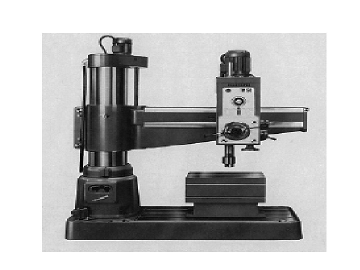
Drilling Machine…

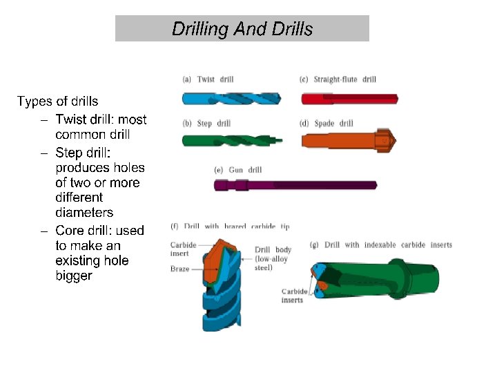
Drilling • Drilling is the operation of producing circular hole in the work-piece by using a rotating cutter called DRILL. • The machine used for drilling is called drilling machine. • The drilling operation can also be accomplished in lathe in which the drill is held in tailstock and the work is held by the chuck. • The most common drill used is the twist drill.

Drilling Machine • • • It is the simplest and accurate machine used in production shop. The work piece is held stationary ie. Clamped in position and the drill rotates to make a hole. Types : a) Based on construction: Portable, Sensitive, Radial, up-right, Gang, Multi-spindle b)Based on Feed: Hand Power driven

Sensitive Drilling Machine • Drill holes from 1. 5 to 15 mm • Operator senses the cutting action so sensitive drilling machine

Up-Right Drilling Machine • Drill holes upto 50 mm • Table can move vertically and radially

Drill Materials The two most common types are 1. HSS drill - Low cost 2. Carbide- tipped drills - high production and in CNC machines Other types are Solid Carbide drill, Ti. N coated drills, carbide coated masonry drills, parabolic drills, split point drill

Tool Nomenclature

Operations in drilling machine

Operations in drilling machine

Types of cutters Reamers : Multi tooth cutting tool Accurate way of sizing and finishing the preexisting hole. Accuracy of 0. 005 mm can be achieved Boring Tool: Single point cutting tool. Boring tool is held in the boring bar which has the shank. Accuracy of 0. 005 mm can be achieved.

Types of cutters Countersinks : Special angled cone shaped enlargement at the end of the hole Cutting edges at the end of conical surface. Cone angles of 60°, 82°, 90°, 100°, 110°, 120° Counter Bore Tool: Special cutters uses a pilot to guide the cutting action. Accommodates the heads of bolts.

Counter bore and spot facing

Types of cutters Combined Countersinks and central drill : Special drilling tool to start the hole accurately. At the end it makes countersinks in the work piece. Gun drill : Machining of lengthy holes with less feed rates. To overcome the heating and short life of the normal drill tool

Types of cutters Tapping: For cutting internal thread Multi cutting edge tool. Tapping is performed either by hand or by machine. Minor dia of the thread is drilled and then tapping is done.
: - It’s the peripheral speed of the drill v")
Definitions • Cutting Speed (v): - It’s the peripheral speed of the drill v = *D*N where D = dia of the drill in m N = Speed of rotation in rpm Feed Rate (f): It’s the movement of drill along the axis (rpm) Depth of Cut (d): The distance from the machined surface to the drill axis d = D / 2

Material Removal Rate: It’s the volume of material removed by the drill per unit time MRR = ( D 2 / 4) * f * N mm 3 / min Machining Time (T) : It depends upon the length (l) of the hole to be drilled , to the Speed (N) and feed (f) of the drill t = L / f N min

Precautions for Drilling machine • Lubrication is important to remove heat and friction. • Machines should be cleaned after use • Chips should be removed using brush. • T-slots, grooves, spindles sleeves, belts, pulley should be cleaned. • Machines should be lightly oiled to prevent from rusting

Safety Precautions • Do not support the work piece by hand – use work holding device. • Use brush to clean the chip • No adjustments while the machine is operating • Ensure for the cutting tools running straight before starting the operation. • Never place tools on the drilling table • Avoid loose clothing and protect the eyes. • Ease the feed if drill breaks inside the work piece.
8c06e8695a8fc8a1c7c0f6dc957b1fe8.ppt