

c2484a10522f96a290833164feebe5d2.ppt
- Количество слайдов: 49
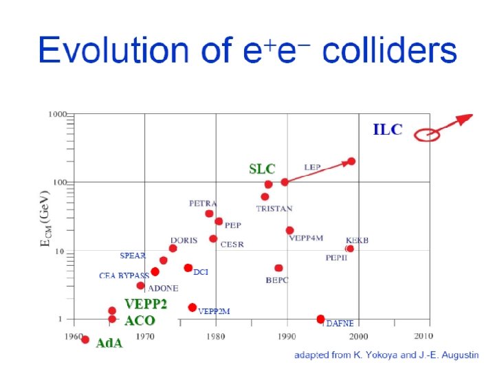
 ATF 2: the linear collider final focus prototype at KEK - an international telescope for nanometre size beams - Philip Bambade Laboratoire de l’Accélérateur Linéaire Université Paris 11, Orsay, France Seminar at Wayne State University, Michigan 11 January 2011
 KEK High Energy Accelerator Research Organization, Tsukuba site, Japan Photon Factory: science with photons STF + ATF : R&D for future high energy e e linear colliders + plans intense laser physics KEKB super. KEKB
 Accelerator Test Facility @ KEK ATF 2 final focus x = 2. 8 -10 m y = 20 -50 nm Damping Ring S-band Linac x = 1. 2 -2 nm y ~ 4 -10 pm
 LAPP LLR
 for") Higgs boson production at threshold Proposal to run near threshold (√s=230 Ge. V) for a light Higgs (120 Ge. V) Reason Higgs mass resolution determined from Higgs-strahlung process e+e- HZ (Z + -, e+e-) with the recoil mass method: LAL 07 -03 is the best due to - better momentum resolution of m±, e± at low energy - larger cross section at 230 Ge. V than at e. g. 350 Ge. V 230 Ge. V 350 Ge. V m. H F. Richard et al.
Higgs boson production at threshold Proposal to run near threshold (√s=230 Ge. V) for a light Higgs (120 Ge. V) Reason Higgs mass resolution determined from Higgs-strahlung process e+e- HZ (Z + -, e+e-) with the recoil mass method: LAL 07 -03 is the best due to - better momentum resolution of m±, e± at low energy - larger cross section at 230 Ge. V than at e. g. 350 Ge. V 230 Ge. V 350 Ge. V m. H F. Richard et al.
 Higgs boson reconstruction at threshold Detailed full MC simulation studies being performed with both Z + -, e+e- channels Improving previous studies with - optimal beam energy choice - realistic beamstrahlung effect (parameterization full simulation) - more efficient e / ID - better background rejection - model independent analysis (not using H decay final state & e / isolation) Preliminary result with channel : Reconstructed spectra for different beam m. H = 120. 010 ± 0. 036 Ge. V (model energies – includes realistic scaling of IP to maintain collimation depth independent) gggg √s = 230 Ge. V L = 500 fb-1 m. H = 120 Ge. V LHC : L=30 fb-1 m. H=120 ± 0. 2 Ge. V


 R&D deliverables from Test Facilities for ILC BDS and DR Test Facility Deliverable Date Hardware development, Optics and stabilisation demonstrations: ATF Demo. of reliable operation of fast kickers meeting the 2010 successful in Oct. 2009 ! specifications for the ILC damping ring. y ~4 -10 pm Generation of y = 1 pm-rad emittance beam < ILC&CLIC spec. 2009 Demo. of compact Final Focus optics (design demagnification, resulting in a nominal 35 nm beam size at focal point). 2010 Demo. of prototype SC and PM final doublet magnets 2012 Stabilisation of 35 nm beam over various time scales. 2012 ATF 2 Electron cloud mitigation studies: Re-config. (re-build) of CESR as low-emittance e-cloud test facility. First meas. of e-cloud build-up using instrumented sections in dipoles and drifts sections (large emittance). CESR-TA 2008 Achieve lower emittance beams. Meas. of e-cloud build up in wiggler chambers. 2009 Characterisation of e-cloud build-up and instability thresholds 2010 as a func. of low vertical emittance (≤ 20 pm) DAΦNE Fast kicker design and pulser reliability check 2010 Characterisation of e-cloud build-up and instability thresholds 2010 15
 Horizontal & vertical emittances at present & planned electron rings ATF meets ILC normalised emittance challenge
 17
17

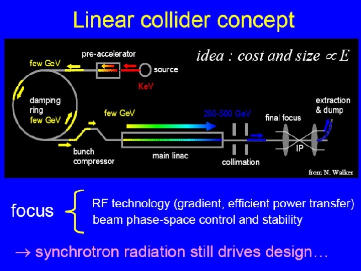
 ATF 2 R&D for linear colliders efficiency Pelec Luminosity ~ E cm efficiency Pelec Ne x y beamstrahlung y, normalised Ecm Parameters ATF 2 ILC CLIC Beam Energy [Ge. V] 1. 3 250 1 3. 5 - 4. 5 5 E-6 / 3 E-8 1 E-5 / 4 E-8 6. 6 E-7 / 2 E-8 IP x/y [mm] 4 / 0. 1 21 / 0. 4 6. 9 / 0. 07 IP ’ [rad] 0. 14 0. 0094 0. 00144 E [%] ~ 0. 1 ~ 0. 3 Chromaticity ~ 1 E 4 ~ 5 E 4 Number of bunches 1 -3 (goal 1) ~ 3000 312 Number of bunches 3 -30 (goal 2) ~ 3000 312 Bunch population 1 -2 E 10 3. 7 E 9 IP y [nm] 37 5. 7 0. 7 beam size control & stability 3. 5 x/y [m. rad] trade-off 1500 L* [m] linac RF + sources cost & feasibility

 ATF 2 = scaled ILC & CLIC final focus new local chromaticity correction P. Raimondi and A. Seryi, Phys. Rev. Lett. 86, 3779 (2001)
 ATF 2 final focus prototype Goal A : nanometer beam size Goal B : trajectory stabilization - obtain y ~ 35 nm at focal point - 1 -2 nm at focal point - reproduce reliably y , maintain in time - intra-train feedback (ILC-like trains) • 2008 construction & installation • 2009 / 2010 commissioning • 2011 / 2012 goals 1 & 2 + instr. R&D • after 2013 continue Linear Collider R&D + new science projects with intense laser 1. Expert training on real system 2. Instrumentation for nano-beams 3. Accelerator RD & operation by multi-partner collaboration ATF 2 COST : ~ 3 + 1 M$ shared by Asia, EU, US

 ATF 2 operation & instrumentation R&D 2 nd order telescope Match optics into FF fine tuning of local errors buffer section for input errors DR extraction setup, stability
 Daily operation meeting in control room 25
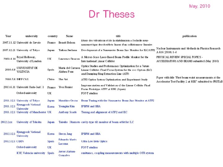
 Jan. – Jun. 2010") Commissioning periods Dec. 2008 3 weeks 2009 21 weeks (=1+2+4+3+3+1+2+2+3) Jan. – Jun. 2010 14 weeks (=3+2+2+3+2+1+1) 1 st cont. week Autumn 2010 7 weeks (=2+2+3) 2 nd continuous week Beam time scheduling 50% fraction for ATF 2 & 4 days per week operation Individual RD tasks & common goals KEK, KNU, Tokyo, Sendai, SLAC, IHEP, UK, France, Spain, CERN, … ATF 2 educational function Several Ph. D & young post-doc researchers in accelerator science
Commissioning periods Dec. 2008 3 weeks 2009 21 weeks (=1+2+4+3+3+1+2+2+3) Jan. – Jun. 2010 14 weeks (=3+2+2+3+2+1+1) 1 st cont. week Autumn 2010 7 weeks (=2+2+3) 2 nd continuous week Beam time scheduling 50% fraction for ATF 2 & 4 days per week operation Individual RD tasks & common goals KEK, KNU, Tokyo, Sendai, SLAC, IHEP, UK, France, Spain, CERN, … ATF 2 educational function Several Ph. D & young post-doc researchers in accelerator science
 reduction paced by beam tuning instrumentation (BSM / other)") Commissioning gradual x, y* (demagnification) reduction paced by beam tuning instrumentation (BSM / other) background study
Commissioning gradual x, y* (demagnification) reduction paced by beam tuning instrumentation (BSM / other) background study
 Variable IP at ATF 2 nominal value y = 0. 0001 m x = 0. 004 m ultra-low upgrade since january 2010 y = 0. 001 m x = 0. 04 m ultra-low upgrade factors 2 -4 10 times nominal values y [m] April - December 2009 March 2009 Now nominal y nominal x 2. 5
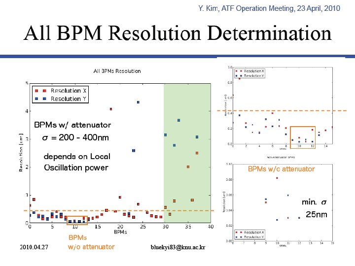
 Instrumentation preparation and R&D • Stripline BPMs, C and S band cavity BPMs, BSM “Shintake”, wire-scanners in most part commissioned and operating satisfactorily (few improvements underway) • IP-cavity BPMs, tilt monitor, OTR profile, LW, FONT actively studied as R&D in preparation for goal 2 (and 1) • Background monitors: PLIC optical fibre + dedicated instrumentation simulation effort coupled to measurements needed to assess ultra low * feasibility


![Reconstructing variations at injection (during dispersion measurements) f. RF [k. Hz] = off 0](https://present5.com/presentation/c2484a10522f96a290833164feebe5d2/image-33.jpg "Reconstructing variations at injection (during dispersion measurements) f. RF [k. Hz] = off 0") Reconstructing variations at injection (during dispersion measurements) f. RF [k. Hz] = off 0 +3 +2 +1 0 -1 -2 -3 -2 -1 0 +1 +2 +3 off Y. Renier et al.
Reconstructing variations at injection (during dispersion measurements) f. RF [k. Hz] = off 0 +3 +2 +1 0 -1 -2 -3 -2 -1 0 +1 +2 +3 off Y. Renier et al.
 Measure X dispersion by changing DR energy Y dispersion from energy fluctuations < 1 e-4 X dispersion from energy fluctuations IP DR Y. Renier et al.

 “Shintake” beam size monitor at IP Sensitivity ranges of crossing angles
 Tuning steps for 1 st ATF 2 continuous tuning run 1. Startup 2. DR tuning 3. EXT & FFS C-band BPM calibration 4. FFS S-band BPM calibration 5. Initial EXT & FFS setup 6. EXT dispersion measurement and correction (x & y) 7. EXT Twiss + emittance calculation at IEX match point (x & y) 8. EXT coupling correction 9. IPBSM preparation 10. Horizontal IP diagnostics 11. Horizontal IP re-matching (if required) 12. Vertical IP diagnostics 13. Vertical re-matching (if required) 14. FFS Model diagnostics (if required) 15. IP multiknob tuning with IPBSM vertical beam size mode - IP y waist, dispersion, coupling scans - IP x waist, dispersion scans - Higher-order terms with d. K / tilts 16. IPBSM study - Study required at changeover points between crossing modes - 2/8 degree mode >~350 nm - 100 nm ~< 30 degree mode ~< 350 nm
 Automated IP waist scans & Twiss measurements
 Multiknobs for
 + systematics…
 Conclusions and prospects • ATF = only fully open facility for R&D in accelerator physics and instrumentation • International training of young Post-Docs, Ph. D and Master students, many through co-supervision • Excellent progress with beam instrumentation, especially BPMs (striplines and cavities), BSM and several other ATF 2 R&Ds • 1 st and 2 nd ATF 2 continuous beam tuning run in May & December Need to plan and support set of regular “goal 1 dedicated” shift blocks for success in 2011 • 300 nm vertical spot (target ~ 100 nm) • ATF operation guaranteed for dedicated LC R&D guarantied to end 2012 – program should continue for LC and extend to other science goals (e. g. strong field physics with intense laser) beyond
 T. Tauchi 1.") Tentative research schedule for 2010 -2015 R&D for ILC (and CLIC) T. Tauchi 1. Continued ILC/CLIC R&D 2. Physics with intense laser not funded, to be reviewed
Tentative research schedule for 2010 -2015 R&D for ILC (and CLIC) T. Tauchi 1. Continued ILC/CLIC R&D 2. Physics with intense laser not funded, to be reviewed
 Additional slides


 Main parameters • • Luminosity ∫Ldt = 500 fb-1 in 4 years • Ability to scan between 200 and 500 Ge. V • Energy stability and precision below 0. 1% • Electron polarization of at least 80% • Present outlook Ecm adjustable from 200 – 500 Ge. V The machine must be upgradeable to 1 Te. V Technical design phased to 2010 -2012 Also developing CLIC ILC
 1 st ATF 2 continuous tuning run May 17 -21, 2010 Day Owl Shift Swing Shift [2] MON Day Shift [2, 3] Kubo / Akagi Woodley, Edu Araki / Miyoshi TUE [3, 4] Hayano / Kim White [5, 6] Furuta / Bambade White, Nelson, Edu, Bambade [6, 7, 8] Omori / Woodley Wang, Seryi, Bolzon, Jones WED [7, 8] Okugi / Shimizu White, Edu, Wang, Jones [8, 9] Mitsuhashi / White Bambade, Nelson, Kamiya, Yamaguchi [10, 11, (14)] Terunama / Bolzon Woodley, Seryi, Oroku, Edu THURS [12, 13, (14)] Fukuda / Sugiyama Woodley, Wang, Jones, Yamaguchi [15, 16] Toge / Aryshev Okugi, Neslon, Bambade, Jones, Kamiya, Edu [15, 16] Naito / Abhay Seryi, White, Bolzon, Oroku, Tauchi FRI [15, 16] Kuroda / Kurihara Woodley, Edu, Wang, Kamiya [15, 16] Sato / Oroku Okugi, White, Nelson, Bambade, Jones, Oroku [15, 16] Okugi / Yamaguchi White, Bolzon, Seryi, Jones, Yamaguchi
 Software tasks organized following “HEP experiment” model are em + appl. softw -Syst Original ATF V : 2 environments control system rtable ht Simulator po Flig