e5d807c640310d0a3591952c315536d9.ppt
- Количество слайдов: 43


Assembly Language Lecture By Shery khan 24 -25 -26 sherykhan 186@gmail. com www. sherykhan. jimdo. com

Agenda n n n n What are Real time Interrupts & Hardware Interfacing? What are I/O Ports? What are IN/OUT Instruction? What are PIC Port? What is Interrupt Chaining? What are TSR? Lastly we study Programmable Interval timer?

Hardware Interrupts n n Single pin outside the processor Called INT PIN that are used for External hardware to generate Interrupt There are many devices that need processor Attention like keyboard , Hard disk , Floppy Disk etc If processor actively monitor all devices instead of being automatically interrupted then Processor cant do any meaningful work

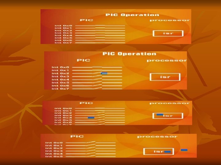
Continue n n n Since there are many devices generating interrupts there is going one pin inside the processor & one pin cannot be technically derived by more than one source a controller is used b/w called programmable Interrupt controller (pic) It has Eight input & single Output The Eight Input signal to Pic are called Interrupt Request

Hardware Interrupt n n Hence “ A hardware Interrupt is a signal Received by the CPU that Tells it to Interrupt Its Current Sequence of Instruction &branch to a new Location. cpu supports 256 Interrupts numbered 0 -FF Hexa decimal “ IRQ Level: Interrupt can be triggered by a number of different devices on PC. Each Device has Priority based on Interrupt level or IRQ level. Level 0 has Highest Priority

What is IRQ? ? n n n There are 8 Sources in Programmable Interrupt Controller You See in BIOS Parallel Port IRQ 3 etc These are 8 input Lines in IBM PC which ar connected to Different Devices The 8 Input signal to Programmable Interrupt are called IRQ Below Table is Explained Highest priority IRQ 0 which is Timer IRQ 1 for Keyboard etc

IRQ vs. INT Mapping n n n Each IRQ is Mapped to specific Interrupt in the system This is Called IRQ & INT Mapping IRQ 0 to 7 consecutively mapped on Int 8 to F This Mapping is Done by PIC not the Processor The Actual Mechanism Fetches one Instruction from PIC whenever an INT PIN is Signaled instead of Memory We can program the pic to generate a different set of INTERRUPT on the same Interrupt Request IRQ 0 is translated to INT 8

Table of IRQ and Interrupts

Table IRQ 0 Interrupt Num 8 1 2 9 0 Ah=10 3 4 5 0 Bh=11 0 Ch=12 0 Dh Description System Timer 18. 2 time/sec Keyboard Programmable Interrupt Controller Serial Port 2 Serial Port 1 LPT 2 (parallel

Priority n n IRQ 0 the Highest Priority Interrupt is generated by the Timer chip frequency and Handler at INT 8 is Invoked which Update the System Time. A key Press generated IRQ 1 and the INT 9 handler is invoked which store this Key

What is IRQ Conflict? ? ? n When Network Card and Sound Card is Fit in the Motherboard of the System and Connected to Processor through IRQ 5 both have Same IRQ at that Situation when 2 outputs sources drive one Input source then we say that IRQ conflict

Working /Mechanism of IRQ & EOI n n when a key is Pressed IRQ 1 is generated and INT 9 Handler which stores the key. When an Interrupt comes Outside the Processor or From a Device it Reaches to PIC as then Processor and Processor Invoke the software related routine now this Routine is working after some time it Tells to PIC that I finish my work so we Acknowledge the PIC BY END OF INTERRUPT so that the Switches which are Open that they Closed and Other Waiting Interrupts Are Come that Processor Serve Them

I/O PORTS n n n Around the Processor the Different Devices like Printer , Video , Keyboard Port , etc How the Processor Communicate with these Devices if Processor Don’t Communicate with These Devices don’t send or Receive data then there no function is performed. So the Processor must Communicate with these Devices these Peripheral Devices are called I/O PORTS

continue n n Processor Communicate with Peripheral devices is Similar as it can Communicate with MEMORY Similar to Memory Operation it can Either Read or Write. Some thing is Happen when Processor Read or Write on I/O PORTS

Separation of Peripheral address &Memory Address Space IBM PC or IAPX 8088 Processor Separate Peripheral Address space from the Memory Address Space n Another Concept is there MEMORY MAPPED I/O: Designated Memory cell Work as a Port for specific devices. (wo input devices jo memory address ka ander hi periphiral adress ko bhe rakhta hain) n

continue n n Processor see only Data Bus & Address Bus Iapx 8088 divides in two parts First is MEMORY Operation (Move is Valid) Secondly one Signal tells that at this Particular time what was the Interest of Processor whether it is Interested in Outside World I/O Ports or whether it is Interested in Memory world

Continue n n n For this Purpose it uses a number which is on Address Bus that Tells the Interest of Processor Iapx 8088 uses a PIN we called as I/O by n bar When this PIN is Level 0 processor Access Memory When this Pin is Level 1 it can Access I/o port Basically the num is on Address bus which indicate that it is of I/O world or Memory world

continue n n n Read & write operation are performed by using same data Bus and Address bus PIN I/O by n bar Differentiate that from which world data is expected So by this way it can read or write the Peripheral Register The I/O space is of 16 bits which mean 64 K Different I/O ports connect to it Which we say that 65536 I/O PORTS are connected to Processor

Continue n n n Keyboard is mapped to I/O ports in this I/o space PIC is mapped , sound card etc ……… There are port address through which communication is done

IN /OUT INSTRUCTION n n n There are two special instruction for read and write I/o ports For read we use IN (port to processor) For Write we use OUT (processor to port) When we use IN/out instead of MOV the Processor Automatically indicate I/O by n bar Indicate that it is read or Write from I/O port There also two variant in BYTE & WORD

Address of the Ports n n n n Port 21 is for PIC (Prog Interrupt controller) Port 61 is for Keyboard Port 378 H is for Parallel Port so on……. . IN: in this Instruction we use a destination Register in which data comes while read from port to processor in Byte case we use AL In Word case we AX Port address is not in segment and Offset form It is Just a NUM and it is Destination so it is DX register

Continue n n n If the port num is less than 255 or it can fit in 8 bit so we cannot use DX or not store in DX register it is written directly in instruction Port num tells us that at some particular time Processor talk to which specific device/ port IN : we can first read and then fetched so register is first written OUT: at there the data is written on port so the destination is port so port number is first written in the instruction All the Rules of MOV instruction are followed ………

Sample

Lecture 25 n n n Keyboard Controller: Keyboard is the collection of labeled button and every button is designated a number (not the Asc. II Code) The number is send to the processor when the Key is Pressed from this number called Scan Code the processor understand which Key was Pressed

Scan Code n n n For Each Key Scan Code comes Twice once the Key press and once for key release Both Scan code are differ in one bit The lower seven bit contain the key number While the Most Significant bit is clear in the Press code and Set in the Release Code If we write Capital A so we First Press Shift Key the Scan Code is Sent then We Pressed A Scan Code is Sent then the Release code of A & release code of Shift Key and Interrupt Handler Understand That Sequence Should Result in ASCII Code of A Interrupt handler REMEMBER the Sequence.

Keyboard Port n n The Keyboard Port is 60 the Keyboard Generate IRQ 1 when Ever Key is Pressed so if we Hooked INT 9 inside the it read Port 60 so we can tell Which Key is Pressed Scan code table is Given Below

Scan code KEYS 1 2 3 4 5 6 7 8 9 10 Scan Code 78 79 7 A 7 B 7 C 7 D 7 E 7 F 80 81

SCAN CODE KEY A B C D E F G H I SCAN CODE 1 E 30 2 E 20 12 21 22 23 17

SCAN CODE KEY J K L M N O P Q R SCAN CODE 24 25 26 32 31 18 19 10 13

SCAN CODE KEYS S T U V W X Y Z SCAN CODE IF 14 16 2 F 11 2 D 15 2 C

SCAN CODE KEYS HOME END Page up Page. Down Left arrow Right Arrow uparrow Dn arrow insert alone 47 4 F 49 51 4 B 4 D 48 50 52 With CTRL KEY 77 75 84 76 72 73 74

USING SCAN CODE PROGRAM n n n in al, 0 x 60 ; Keyboard Port cmp al, 0 x 47……………HOME KEY jne nextcmp: cmp al, 0 x 4 B ; Left arrow …………. . LEFT jne nomatch
![THAT’S PROGRAM n n n n [org 0 x 0100] jmp start keyboard. ISR:](https://present5.com/presentation/e5d807c640310d0a3591952c315536d9/image-34.jpg "THAT’S PROGRAM n n n n [org 0 x 0100] jmp start keyboard. ISR:")
THAT’S PROGRAM n n n n [org 0 x 0100] jmp start keyboard. ISR: push ax push es mov ax, 0 xb 800 mov es, ax in al, 0 x 60 ; Keyboard Port………………. . cmp al, 0 x 47………………………. . jne nextcmp mov byte [es: 0], 'H' jmp nomatch nextcmp: cmp al, 0 x 4 B ; Left arrow……………………. . jne nomatch mov byte [es: 0], 'L'

continue n n n n nomatch: mov al, 0 x 20 out 0 x 20, al pop es pop ax iret start: xor ax, ax mov es, ax cli mov word [es: 9*4], keyboard. ISR mov [es: 9*4+2], cs sti li: mov ah, 0 int 0 x 16

Lecture 26 Basic OS Understanding In MS DOS Memory point of View we see first IVT then Os Different Things Appear n Then BIOS Data Area , Dos Data Area , IO. sys Then MS Dos. sys and Device driver are loaded Then the MS Dos Command Interpreter is Loaded Lastly the area which is Free for us called Transient Program Area n

What is Meant For Transient? ? n n We say this Area Transient because in this Area our Programs are loaded , Executed and after there Specific Work the Free this Area so that this Area is Utilized by other program so that it is Called Transient Area. Mechanism : Dos maintain a Pointer which is called Free Mem from where the TPA is Started it Dos Pointer is Started and Remember the Position and it is Own word to the RAM 640 K it is there

Free Min Pointer Working n n When Ever a program is Loaded to this Memory the Free Min Pointer gives a Control to Program when the Program Executed Finishes the Last to lines 4 c Terminator Lines Return the Control to Free min Pointer And FREED the Space of TPA Legal control return to DOS

Termination n n One way is to Freed all Memory and Return Control to Dos and Free Min Pointer is Start Pointing start of the TPA Second way is that Free Min Pointer Stop Deallocation at some point were I say and some Part of Program is Retain in this memory and make it Part of OS. or Some part of Program Resident at there leave the some part of program in this Memory. Termination is Done Control Return but some Part of Program Remain there and Pointer start Pointing after that ………….

TSR n n Terminate & stay Resident : above the Phenomena is Explain is Called TSR Control Return to Dos Some Part Is Remain There in we say Resident We say it is Extension of Command Prompt and Not Over written from There Free Min Pointer is Starting New Programs are Executed after my Resident Program

How Much memory we Can Resident? ? ? n n n We Can Resident Memory in Multiples of 16 Byte we say that 32 byte, 48, 64 These are in paragraph which is chunk of 16 Bytes and its Multiples Labeling is Done when we Resident Round. Up is Done And Calculation is Label Offset +15/16=round up We know that 4 shift right is equal to division of 16 so we use SHR while Doing Round UP

Programmable Interval Timer n n n PIT is Important Peripheral Device chip numbered is 8254 Chip has Fixed Frequency 1. 1938 MHZ Inside the chip 16 Bit Divisor which Divide the Input Frequency and output is Connected to IRQ 0 line of PIC 0 means a divisor of 65536 1193180/65536=18. 2 timer per sec this is called Timer TICK In one Sec 55 ms times a IRQ 0 is Coming so these Timer Tick Are Counted and IBM PC maintain His TIME

THAT’S ALL n n n n THANKS FOR LISTENING ME FEED BACKS sherykhan 186@gmail. com www. sherykhan. jimdo. com www. skvu. blogspot. com RESPECT YOUR PARENTS …………. ALLAH HAFIZ
e5d807c640310d0a3591952c315536d9.ppt