

18ded6bfd990e8578a8269f4d5a68018.ppt
- Количество слайдов: 72
 ASME SECT. VIII DIV-I CODES, STANDARDS & SPECIFICATIONS
 ASME Section VIII Division-1, 2 & 3 Historical Development of ASME Section VIII Div- 1, 2 & 3 – In the early 20 th century, explosion of steam boilers in U. S was frequent. Occurring rate 1/day. – 1914: ASME Boiler and pressure vessel code is published. – 1925: First publication of Section VIII – Unfired Pressure Vessels. – 1934: API+ASME jointly published unfired pressure vessel code for petroleum industry. – 1952: These two codes are merged in to single code: ASME Unfired Pressure Vessel Code Section VIII – 1968: ASME Section VIII Div-2 is published and original code became Div-1 – 1997: ASME Sec VIII division 3 is published.
 ASME Section VIII Division-1, 2 & 3 ASME Section VIII codes are most widely used worldwide. Section VIII is divided into three divisions: – Division 1: Rules for construction of pressure vessels – Division 2: Alternative Rules for construction of pressure vessels. – Division 3: Alternative Rules for construction of high pressure vessels. Division 1 is used most often since it contains sufficient requirements for majority of pressure vessels. The main objective of ASME Code rules is to establish the minimum requirements that are necessary for safe construction and operation. ASME Code defines the requirements for material, design, fabrication, inspection and testing which are needed to achieve a safe design.
 ASME Section VIII Division-1 Scope: – Applicable for pressure between 15 psig and 3000 psig. – Code requirements do not apply to non pressure parts, however welds which attach non pressure parts shall meet code rules.
 World Wide Pressure Vessel Codes Different industrial nations, institutions and organizations have developed standards and codes of the pressure vessel for – Design – Fabrication – Inspection These codes and standards help the Design, Fabrication, Inspection engineer to size the vessel properly for its safe operation. Advantages of design codes: – Proven design based on experience. – Inbuilt factor of safety. – Amendments of codes are being done at regular interval based on feed back data, design improvements and technological up gradation in materials and fabrication processes.
 ASME Section VIII Division-1 Scope: – Code identifies specific items for which it is not applicable. This includes: Fired process tubular heaters (e. g. furnaces). Pressure containers which are integral part of mechanical devices (e. g. pumps, turbines). Piping system and their components.
 ASME BOILER & PRESSURE VESSELS CODES I. POWER BOILERS II. MATERIAL SPECIFICATIONS III. NUCLEAR POWER PLANT COMPONENTS IV. HEATING BOILERS V. NONDESTRUCTIVE EXAMINATION VI. RECOMMANDATED RULES FOR CARE & OPERATION OF HEATING BOILERS VII. RECOMMANDATED RULE FOR CARE OF POWER BOILERS VIII. PRESSURE VESSELS –DIVISION-1 , DIVISION-2 & DIVISION-3 IX. WELDING & BRAZING QUALIFICATIONS. X. FIBERGLASS-REINFORCED PLASTIC PRESSURE VESSELS XI. RULES FOR INSERVICE INSPECTION OF NUCLEAR POWER PLANT COMPONENTS XII. RULES FOR CONSTRUCTION AND CONTINUED SERVICE OF TRANSPORT TANKS.
 ASME Section VIII Division-1 Structure of Sec VIII Div-1: It is divided into three subsections: – Subsection A: It consists part UG, general requirements for Method of construction. that apply to all pressure vessel parts, – Subsection B: It covers requirements that apply to various fabrication methods. Subsection B consists of – Part UW for welded construction Part UF forged construction Part UB for brazed construction - Subsection C: It covers requirements for several classes of material.
 Structure of ASME Section VIII Div-1 ASME SEC –VIII DIV- 1 Consists of: – Introduction -U – Subsection A -General Requirements (Part UG) – Subsection B -Specific Requirements - Methods (Parts UW, UF, UB) – Subsection C -Specific Requirements - Materials (Parts UCS, UNF, UHA, UCI, UCL, UCD, UHT, ULW, ULT, UHX) – Mandatory Appendices -Appendix 1 to 33 – Non Mandatory Appendices -Appendix A, C, … FF, GG (20 nos. )
 Subsection A -General Requirements Part UG : General Requirements for all Methods of Construction and all Materials – Materials UG-4 to UG-15 – Design UG-16 to UG-35 – Openings and Reinforcement UG-36 to UG-46 – Braced and stayed surfaces UG-47 to UG-50 – Ligaments UG-53 to UG-55 – Fabrication UG-75 to UG-85 – Inspection and Tests UG-90 to UG-103 – Markings and Reports UG-115 to UG-120 – Pressure Relief Devices UG-125 to UG-137
 Subsection B -Requirements pertaining to methods of Fabrication of Pressure Vessels Part UW : Requirements for Pressure vessels fabricated by Welding – – – – General UW-1 to UW-3 Materials UW-5 Design UW-8 to UW-21 Fabrication UW-26 to UW-42 Inspection and Tests UW-46 to UW-53 Markings and Reports UW-60 Pressure Relief Devices UW-65 Part UF : Requirements for Pressure vessel fabricated by Forging Part UB : Requirements for Pressure vessel fabricated by Brazing
 Subsection C -Requirements pertaining to Classes of Materials Part UCS – Requirements for Pressure Vessels Constructed of Carbon and Low Alloy Steels Part UNF – Requirements for Pressure Vessels Constructed of Non Ferrous Materials Part UHA – Requirements for Pressure Vessels Constructed of High Alloy Steel Part UCI – Requirements for Pressure Vessels Constructed of Cast Iron Part UCL – Requirements for Welded Pressure Vessels Constructed of Material non corrosion resistant, Integral Cladding, Weld Metal Overlay, Cladding or with Applied Linings Part UCD – Requirements for Pressure Vessels Constructed of Cast Ductile Iron
 Part UHT – Requirements for Pressure") Subsection C -Requirements pertaining to Classes of Materials(Continued) Part UHT – Requirements for Pressure Vessels Constructed of Ferritic Steels with Tensile Properties enhanced by Heat Treatment Part ULW – Requirements for Pressure Vessels Constructed of Layered Construction Part ULT – Alternative Rules for Pressure Vessels Constructed of Material having higher allowable stresses at lower temperatures Part UHX – Rules for Shell and Tube Heat Exchangers
Subsection C -Requirements pertaining to Classes of Materials(Continued) Part UHT – Requirements for Pressure Vessels Constructed of Ferritic Steels with Tensile Properties enhanced by Heat Treatment Part ULW – Requirements for Pressure Vessels Constructed of Layered Construction Part ULT – Alternative Rules for Pressure Vessels Constructed of Material having higher allowable stresses at lower temperatures Part UHX – Rules for Shell and Tube Heat Exchangers
 ASME SEC VIII DIV 1 COVERS THE DESIGN OF PRESSURE COMPONENTS AS LISTED BELOW --------------------------------------------------UG-27 ----- THK OF SHELLS UNDER INTERNAL PRESSURE UG-28 ----- THK OF SHELLS UNDER EXTERNAL PRESSURE UG-29 -----STIFFENING RINGS OF CYLINDRICAL SHELLS UNDER EXTERNAL PRESSURE 4. UG-32 & 33 ---- FORMED HEAD , COVERS ELLIPSOIDAL, TORISHERICAL, HEMISHERICAL, CONICAL & TORICONICAL HEADS. 5. UG-34 ---- UNSTAYED FLAT HEADS & COVERS 6. UG-36 & 37 ---- OPENING IN PRESSURE VESSELS & REINFORCEMENTS 7. UG-41 ---- STRENGTH OF REINFORCEMENTS 8. UG -47 ----- BRACED & STAYED SURFACE 9. UG – 53 – LIGAMENT 10. UW-12 & 15 – WELD EFFICIENCY & WELDED CONNECTION DESIGN 11. UCS -56 – REQUIRMENT OF PWHT 12. UG -99 & 100 – HYDROTEST & PNUMATIC TEST REQUIREMENT 1. 2. 3.
 PRESSURE VESSEL ASME SEC VIII DIV 1 --------------------------------------------------UG-27 ----- THK OF SHELLS UNDER INTERNAL PRESSURE UG-28 ----- THK OF SHELLS UNDER EXTERNAL PRESSURE UG-29 -----STIFFENING RINGS OF CYLINDRICAL SHELLS UNDER EXTERNAL PRESSURE UG-32 & 33 ---- FORMED HEAD , COVERS ELLIPSOIDAL, TORISHERICAL, HEMISHERICAL, CONICAL & TORICONICAL HEADS. UG-34 ---- UNSTAYED FLAT HEADS & COVERS UG-36 & 37 ---- OPENING IN PRESSURE VESSELS & REINFORCEMENTS UG-41 ---- STRENGTH OF REINFORCEMENTS UG -47 ----- BRACED & STAYED SURFACE UG – 53 – LIGAMENT
 UW-12 & 15 – WELD EFFICIENCY & WELDED CONNECTION DESIGN UCS -56 – REQUIRMENT OF PWHT UG -99 & 100 – HYDROTEST & PNUMATIC TEST REQUIREMENT
 ASME Section VIII Division-1 Division 1 also consists mandatory and non mandatory appendices: – Mandatory Appendices: It addresses the subjects that are not covered elsewhere in the code. Requirements of this appendices are mandatory. – Nonmandatory Appendices: It provides information and suggested good practices. Requirements of these appendices are not mandatory unless specified in purchase order.
 ASME Section VIII Division-2 – Scope of division 2 is identical to that of division 1, however there is no limitation on higher pressure. – Allowable stress values are higher for division 2 that division 1, hence division 2 vessels are thinner – Vessels constructed with division 2 are economical over division 1 when saving in material cost is higher than the additional cost required to meet stringent requirements of division 2. – Economical for higher pressure applications and for more expensive alloy materials.
 ASME Section VIII Division 1 and 2
 ASME Section VIII Division-3 – Applied to vessels operating at internal or external design pressure is generally above 10000 psig. – Design rules: Maximum shear stress Elastic plastic analysis Fracture mechanics evaluation – Material and NDE requirements more stringent than division 1 and 2
 PARTS OF THE PRESSURE VESSELS 1. HEADS/END CLOSURES 2. SHELL 3. NOZZLES 4. SUPPORTS 5. NOZZLE REINFORCEMENT PADS 6. INTERNALS & EXTERNAL ATTACHMENTS
 Design considerations FOLLOWING LOADINGS TO BE CONSIDERED IN DESIGNING THE VESSELS AS PER ASME SEC. VIII DIV. I ( CLAUSE UG-22) 1. INTERNAL DESIGN PRESSURE AT DESIGN TEMPRATURE. 2. EXTERNAL DESIGN PRESSURE AT DESIGN TEMPRATURE. 3. WEIGHT OF THE VESSEL AT OPERATING AND TEST CONDITION. 4. LOAD DUE TO ATTACHED EQUIPMENTS. 5. WELD JOINT EFFICIENCY. 6. EXTERNAL / INTERNAL ATTACHMENT 7. SEISMIC LOADING. 8. WIND LOADING. 9. FATIGUE LOADING DUE TO THERMAL AND PRESSURE VARIATIONS. 10. CORROSION ALLOWANCES.
 WHAT IS PRESSURE VESSEL ? • PRESSURE VESSEL IS CONTAINER FOR THE CONTAINMENT OF PRESSURE, EITHER INTERNAL OR EXTERNAL. THIS PRESSURE MAY BE OBTAINED FROM AN EXTERNAL SOURCE, OR BY THE APPLICATION OF HEAT FROM A DIRECT OR INDIRECT SOURCE, OR ANY COMBINATION THEREOF. • TYPE OF VESSELS DEPENDING UPON THE ORIENTATION: 1. HORIZONTAL VESSEL 2. VERTICAL VESSEL • TYPE OF VESSEL DEPENDING UPON THE FUNCTIONS : 1. STORAGE VESSEL 2. COLUMNS / ADSORBERS 3. SHELL & TUBE HEAT EXCHANGER
 SHELL • SHELL IS THE MAIN PART OF THE VESSEL. • TYPES OF THE SHELL 1. CYLINDRICAL SHELL 2. SPHERICAL SHELL • DESIGN OF CYLINDRICAL SHELL UNDER INTERNAL PRESSURE AS PER ASME SEC-VIII DIV-1, CL. UG-27. • FOR EXTERNAL DESIGN PRESSURE, SHELL TO BE DESIGN AS PER ASME SEC-VIII DIV-1 CL. UG-28
 VESSEL CONSTRUCTION Circ. Seam Long. Seam D’end Shell Nozzle
 Typical Vessel BOT SPOOL D-End CIRC. SEAM LONG SEAM D/E SEAM MANWAY NOZZLE D-End SHELL NOZZLE
 HEADS / ENDCLOSURES • HEAD IS THE PART WHICH CLOSES THE END OPENING OF THE CYL. SHELL • TYPES OF THE HEADS : 1. HEMISPHERICAL HEAD 2. ELLIPTICAL HEAD 3. TORISPHERICAL HEAD 4. CONICAL HEAD 5. TORICONICAL HEAD 6. BOLTED BLIND FLANGE • DESIGN OF ELLIPTICAL HEAD UNDER INTERNAL PRESSURE AS PER ASME SEC-VIII DIV-1, CL. UG-32. FOR EXTERNAL DESIGN PRESSURE, HEAD TO BE DESIGN AS PER ASME SEC-VIII DIV-1 CL. UG-33
") Formed Heads (Continued…)
Formed Heads (Continued…)
 SINGLE PIECE DISHEND
 CROWN & PETAL D’END Petals Crown Plate Petal Plate
") TORISPHERICAL DISHEND Seamless(one-piece head)
TORISPHERICAL DISHEND Seamless(one-piece head)
 HEMISPHERICAL DISHEND Spherical seamless head(ID 3. 4 mt. , 92 mm. Thk. , steel SA 387 Gr 11)
") FLAT HEADS Flat Head (OD 4. 1 mt, Knuckle radius 100 mm)
FLAT HEADS Flat Head (OD 4. 1 mt, Knuckle radius 100 mm)
 BOLTED BLIND FLANGE Detail of Manhole
 NOZZLES / CONNECTIONS • NOZZLES ARE THE OPENINGS PROVIDED IN THE SHELL/ HEAD FOR CONNECTING THE EXTERNAL PIPING WITH VESSEL. • NOZZLES CONSISTS OF NOZZLE NECK, FLANGE & RF PAD • TYPES OF THE NOZZLES / CONNECTIONS : 1. PIPE NECK WITH FLANGE CONNECTION 2. FORGED NECK WITH FLANGE CONNECTION NOZZLE NECK TO BE DESIGNED AS PER ASME SEC VIII DIV I CL. UG-45 • RF PAD FOR THE NOZZLE TO BE DESIGNED AS PER ASME SEC VIII DIV I CL. UG-36 • NON STD. FLANGE TO BE DESIGNED AS PER ASME SEC VIII DIV I, APPX-2 & STD FLANGE TO BE SELECTED AS PER UG-44/ASME B 16. 5
 Nozzle Details
 SUPPORTS FOR VESSEL • SUPPORTS ARE REQUIRED FOR THE INSTALLATION OF THE VESSEL ON THE FOUNDATION. • TYPE OF SUPPORTS 1. LEG TYPE SUPPORT 2. SKIRT TYPE SUPPORT (CYLINDRICAL/CONICAL) 3 BRACKET TYPE SUPPORT 4. SADDLE SUPPORT –
 SKIRT DETAIL
 Detail of Skirt
 MATERIAL OF CONSTRUCTION FOR VESSEL • ASME LISTS THE DIFFERENT TYPES OF THE MATERIAL FOR PLATES, FORGINGS, PIPES, TUBES, FLANGES & FITTING. --- ASME SEC II PART A, B, C & D • REFER TABLE UCS-23 FOR CARBON AND LOW ALLOW STEEL • REFER TABLE UHA-23 FOR HIGH ALLOY STEEL.
 FABRICATION REQUIREMENTS 1. WELD JOINT CATEGORIES AS PER UW-3 2. WELD JOINT EFFICIENCY AS PER UW-12 3. WELDING OF NOZZLES WITH SHELL AS PER UW-16 4. WELDING/WELDER QUALIFICATION AS PER ASME SEC IX 5. PWHT REQUIREMENT AS PER ASME SEC VIII DIV. 1 , CL. UG-56 6. IMPACT TEST REQUIREMENT AS PER UCS-65/66
 ASME Section VIII Division-1: Fabrication It covers the fabrication requirements as listed below – – Weld joint categories as per UW-3 Weld joint efficiency as per UW – 12 Welding of nozzles with shell as per UW – 16 Welding/welder qualification as per ASME Sec IX – PWHT requirement as per UG-56 – Impact test requirement as per UCS-65 & UG 84
 ASME Section VIII Division-1: Fabrication Weld Joint Categories UW-3
 NDT TESTING • ALL BUTT JOINTS TO BE RT/UT/MPT/DP TESTED AS PER ASME CODE REQUIREMENT • ALL CORNER JOINTS e. g. NOZZLE TO SHELL JOINT SHALL BE MPT/DP TESTED. • ALL FILLET WELDS SHALL BE DP TESTED. • ACCEPTANCE CRITERIA FOR NDT REQUIREMENT FOR WELD JOINT Appendix 4 Rounded Indications Charts Acceptance Standard for Radiographically Determined Rounded Indication in Welds Appendix 6 Methods for Magnetic Particle Examination (MT) Appendix 8 Methods for Liquid Penetrate Examination (PT) Appendix 12 Ultrasonic Examination of Welds (UT) • EQUIPMENT TEST : - HYDROTEST --> 1. 3 x DESIGN PRESSURE (UG-99) – PNEUMATIC TEST ---> 1. 1 x DESIGN PRESSURE (UG-100) • OFFICIAL STAMP FOR CODED VESSELS – ‘U’ STAMPS --- ASME SEC. VIII DIV. 1
 PREHEATING REQUIREMENT PREHEATING REDUCES THE SUSCEPTIBILTY OF THE WELDMENT TO COLD CTACKING /HYDROGEN CRACKING PREHEATING REQUIREMENTS DEPENDING ON THE CARBON EQUIVALENT (CE) CE % SUGGESTED TEMP UP TO 0. 45 % OPTIONAL 0. 45 % TO 0. 60 % 200 -400 F ABOVE 0. 60 % 400 – 700 F EFFECT OF PREHEATING : 1. ELIMINATES THE DANGER OF CRACK FORMATION 2. MINIMIZES HARD ZONE ADJACENT TO WLED 3. MINIMIZES THE SHRINKAGE STRESS 4. MINIMIZES THE DESTORTION
 POST WELD HEAT TREATMENT OBJETCIVE: 1. TO REDUCE THE RESIDUAL STRESSES AT WELD & HAZ 2. TO MODIFY THE MICRO-STRUCTURE (HAZ) EFFECT: 1. SUSCETIBLITIES TO BRITTLE FAILURE DECREASES. 2. RESISTANCE TO STRESS CORROSION CRACKING INCREASES. 3. DIMENSIONAL STABILITIES INCREASES. PWHT PARAMETER 1. HEATING RATE 2. SOAKING TEMPERATURE 3. COOLING RATE
 UCS-56 – PWHT") Part UCS (Continued…) UCS-56 – PWHT
Part UCS (Continued…) UCS-56 – PWHT
 CODE EXTRACT FOR HEAT TREATMENT
 Code Requirements for PWHT Material Normal Holding Temperatur e °C Minimum holding time at normal temperature for nominal thickness Up to 2’’ Over 2’’ to 5’’ Over 5’’ P - No. 1, P - No. 3 [e. g. SA 516 GR 60/7 0] 595 1 hr / in. 15 minimum 2 hr plus 15 min for each additional inch over 2’’ P - No. 4 [e. g. SA 387 GR 11] 650 1 hr / in. 15 minimum 1 hr / inch 5 hr plus 15 min for each additional inch over 5’’ P - No. 5 A P - No. 5 B P - No. 5 C [Group no. 1 ] [e. g. SA 387 GR 22/ SA 540 Ty. D Cl. 4 a] 675 1 hr / in. 15 minimum 1 hr / inch 5 hr plus 15 min for each additional inch over 5’’ P - No. 5 B Group no. 2 [e. g. SA 387 GR 91] 705 1 hr / in. 15 minimum 1 hr / inch 5 hr plus 15 min for each additional inch over 5’’
 REQUIREMENT OF PRODUCTION CONTROL TESTING- PTC REQUIREMENT PTC SIMULATES THE ACTUAL WELD JOINT WITH THE BASE MATERIAL & WELDING CONSUMABLES FROM THE SAME HEAT & MELT AS THOSE USED IN ACTUL JOINT. THE PTC UNDERGOES IDENTIAL FABRICATION SEQUENCE, DONE BY THE SAME WELDERS, SAME WELDING PARAMETERS WITH SAME CONSTAINTS SIMULATED AS THAT OF JOB. TYPES OF PRODUCTION TEST COUPONS 1. THE SMULATED WELD COUPON – STC 2. THE FINAL TEST COUPON – FTC STC – THIS IS BASICALLY THE TEST COUPON OF THE WELD JOINT, WHICH IS SUBJECTED TO THE SIMULATED HEAT TREATMENT CYCLE, TAKING INTO ACCOUNT OF ALL POSSIBLE EVANTUALITIES LIKE REPAIRE, ADDITIONAL HEAT TREATMENT ETC. FTC – THIS IS BASICALLY THE TEST COUPON OF THE WELDMENT, WHICH IS SUBJECTED TO THE ACTUAL HAET TREATMENT SEEN IN THE JOB. THIS COUPON IS MADE SIMULTANEOUSLY WITH THE JOB.
 HYDRO & PNUMATIC TESTING OF PRESSURE VESSEL HYDROTESTING IS TO DONE AS PER ASME SEC VIII DIV-1 -CL UG-99 HYDROTEST PRESSURE = 1. 3 X (P design) x (allow stress at test temp/ allow stress at design temp) HYDROTEST STRESS SHOULD NOT EXCCED 90 % OF THE YIELD STRESS ---------------------------------------------------------PNUMTAIC TESTING IS TO BE DONE AS PER ASME SEC VIII DIV 1 –CL UG 100 PNUMATIC TEST PRESSURE = 1. 1 X DESIGN PRESSURE THE METAL TEMPERATURE DURING PNUMATIC TESTING SHALL BE MAINTAINED ATLEAT 17 DRG C ABOVE THE MDMT TO MINIMISE THE RISK OF BRITTLE FRACTURE.
 HYDROTEST WATER FILLING, PRESSURISING & INSPECTION
 HYDROTEST WATER FILLING, PRESSURISING & INSPECTION
 Sketch for Hydro test


 ASME BOILER & PRESSURE VESSEL CERTIFICATES OF AUTHORIZATION & CODE SYMBOL STAMPS SYMBOL/STAMP CODE BOOKS REQUIRED ---------------------------------------- 1. “A” ( ASSEBLY BOILER) --- B 31. 1 &SEC- 1 & SEC II –C 2. “U”(PRESSURE VESSEL) ---- ASME SEC VIII DIV -1 3. “U 2”(PRESSURE VESSEL) ---- ASME SEC VIII DIV-2 4. “U 3” (HIGH PV) ----- ASME SEC VIII DIV- 3 4. “S” (POWER BOILER) ------ B 31. 1 & SEC-1 5. “UV” (PV SAFETY VALVE)----ASME SEC VIIII DIV -1 /2 6. “V” (BOILER SAFETY VALVE) ----- SEC -1 7. “qp” (PRESSURE PIPING) ------ B 31. 1 & SEC -1
 PRESSURE VESSEL CODE ASME SECTION VIII DIVISION 1
") Introduction to ASME Codes (Section I to Section XII)
Introduction to ASME Codes (Section I to Section XII)
 A Brief Discussion on ASME Section VIII Divisions 1 and 2 and Division 3 Section VIII Div. 1 “Unfired” Pressure Vessel Rules Section VIII Div. 2 Section VIII Div. 3 Alternative Rules for High Pressure Published <1940 1968 1997 Pressure Limits Normally up to 3000 psig No limits either way, usually 600+ psig No limits, Normally from 10, 000 psig General, Construction Type & Material U, UG, UW, UF, UB, UCS, UNF, UCI, UCD, UHT, ULT General, Material, Design, Fabrication and others AG, AM, AD, AF, AR, AI, AT, AS Organisation Design Factor 3. 5 on tensile and other yield and temperature considerations Design Factor 3 on tensile (lower factor under reviewed) and other yield and temperature considerations Similar to Division 2 KG, KM, KD, KF, KR, KE, KT, KS Yield based with reduction factor for yield to tensile ratio less than 0. 7
 A Brief Discussion on ASME Section VIII Divisions 1 and 2 and Division 3 Section VIII Div. 1 Section VIII Div. 2 Section VIII Div. 3 “Unfired” Pressure Vessel Rules Alternative Rules for High Pressure Design Rules Membrane-Maximum stress Generally Elastic analysis Very detailed design rules with Quality (joint efficiency) Factors. Little stress analysis required, pure membrane without consideration of discontinuities controlling stress concentration to a safety factor of 3. 5 or higher Shell of Revolution – Max. Shear stress Generally Elastic Analysis Membrane + Bending. Fairly detailed design rules. In addition to the design rules, discontinuities, fatigue and other stress analysis considerations may be required unless exempted and guidance provided for in Appendix 4, 5 and 6 Maximum shear stress Elastic/plastic Analysis and more. Some design rules provided; Fatigue analysis required, Fracture mechanics evaluation required unless proven leakbefore-burst, Residual stresses become significant and may be positive factors Experimental stress Analysis Normally not required Introduced and may be required Experimental design verification but may be exempted
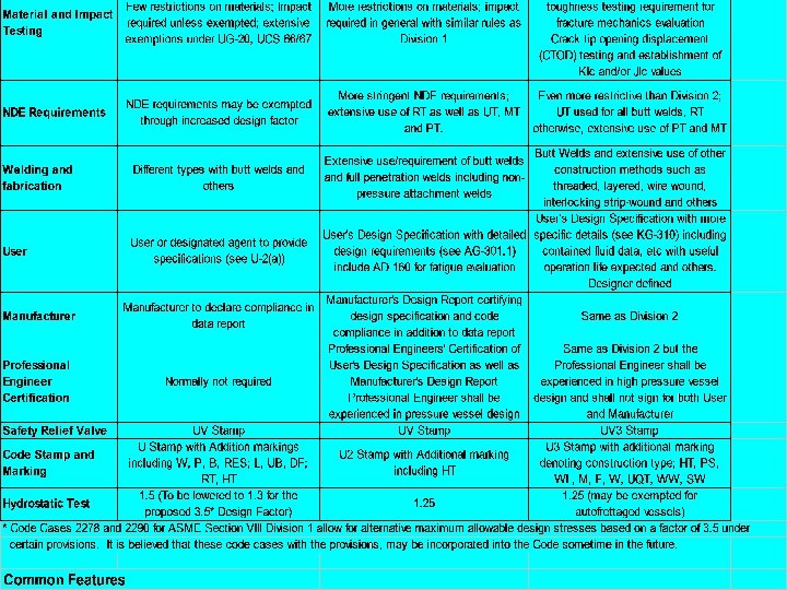
 A Brief Discussion on ASME Section VIII Divisions 1 and 2 and Division 3 Section VIII Div. 1 Section VIII Div. 2 Section VIII Div. 3 “Unfired” Pressure Vessel Rules Alternative Rules for High Pressure Material and Impact Testing Few restriction on materials; Impact required unless exempted, extensive exemptions under UG 20, UCS 66/67 More restriction of materials; impact required in general with similar rules as Division 1 Even more restrictive than Division 2 with different requirements. Fracture toughness testing requirement for fracture mechanics evaluation crack tip opening displacement (CTOD) testing and establishment of Klc and/or Jlc values NDE requirements may be exempted through increased design factor More stringent NDE requirements, extensive use of RT, as well as UT, MT and PT. Even more restrictive than Division 2, UT used for all butt welds, RT otherwise, extensive use of PT and MT NDE Requirements
 A Brief Discussion on ASME Section VIII Divisions 1 and 2 and Division 3 Section VIII Div. 1 Section VIII Div. 2 Section VIII Div. 3 “Unfired” Pressure Vessel Rules Alternative Rules for High Pressure Welding and Fabrication Different types with butt welds and others Extensive use/requirement of butt welds and full penetration welds including non pressure attachment welds Butt welds and extensive use of other construction methods such as threaded, layered, wire-wound, interlocking stripwound and others User or designated agent to provide specifications (see U-2(a)) User’s Design Specification with detailed design requirements (see AG-301. 1) include AD 160 for fatigue evaluation User’s Design specification with more specific details (see KG-310) including contained fluid data, etc. with useful operation life expected and others. Designer defined. User
 A Brief Discussion on ASME Section VIII Divisions 1 and 2 and Division 3 Section VIII Div. 1 Section VIII Div. 2 Section VIII Div. 3 “Unfired” Pressure Vessel Rules Alternative Rules for High Pressure Manufacturer to declare compliance in data report Manufacturer’s Design Report certifying design specification and code compliance in addition to data report Same as Division 2 Normally not required Professional Engineers’ Certification of User’s Design Specification as well as Manufacturer’s Design report Professional Engineer shall be experienced in pressure vessel design Same as Division 2 but the Professional Engineer shall be in high-pressure vessel design and shall not sign for both User and Manufacturer. Professional Engineer Certification
 A Brief Discussion on ASME Section VIII Divisions 1 and 2 and Division 3 Section VIII Div. 1 “Unfired” Vessel Rules Safety Relief Valve Pressure UV Stamp Section VIII Div. 2 Alternative Rules UV Stamp Section VIII Div. 3 Alternative Rules for High Pressure UV 3 Stamp Code Stamp and Marking U Stamp with Addition marking including W, P, RES, L, UB, DF, RT, HT U 2 Stamp with Additional marking including HT U 3 Stamp with additional marking denoting construction type, HT, PS, WL, M, F, W, UQT, WW, SW Hydrostatic Test 1. 3 (was 1. 5 before the use of the 3. 5 Design factor in the 1999 Addenda) 1. 25
 Mandatory Appendices Appendix 1 Supplementary Design Formulas Appendix 2 Rules for Bolted Flange Connections With Ring Type Gaskets Appendix 3 Definitions Appendix 4 Rounded Indications Charts Acceptance Standard for Radiographically Determined Rounded Indication in Welds Appendix 5 Flanged and Flued or Flanged Only Expansion Joints Appendix 6 Methods for Magnetic Particle Examination(MT) Appendix 7 Examination of Steel Castings Appendix 8 Methods for Liquid Penetrate Examination (PT) Appendix 9 Jacketed Vessels Appendix 10 Quality Control System Appendix 11 Capacity Conversion for Safety Valves Appendix 12 Ultrasonic Examination of Welds (UT)
 Appendix 13 Vessels of Noncircular Cross Section Appendix 14 Integral Flat") Mandatory Appendices (continued) Appendix 13 Vessels of Noncircular Cross Section Appendix 14 Integral Flat Heads With a Large, Single, Circular, Centrally Located Openings Appendix 16 Submittal of Technical Inquiries to the Boiler and Pressure Vessel Committee Appendix 17 Dimpled or Embossed Assemblies Appendix 18 Adhesive Attachments of Name Plates Appendix 19 Electrically Heated or Gas Fired Jacketed Steam Kettles Appendix 20 Hubs Machined From Plates Appendix 21 Jacketed Vessels Constructed of Work-Hardened Nickel Appendix 22 Integrally Forged Vessels Appendix 23 External Pressure Design of Copper, Copper Alloy, Titanium Alloy condenser and Heat Exchanger Tubes With Integral Fins
Mandatory Appendices (continued) Appendix 13 Vessels of Noncircular Cross Section Appendix 14 Integral Flat Heads With a Large, Single, Circular, Centrally Located Openings Appendix 16 Submittal of Technical Inquiries to the Boiler and Pressure Vessel Committee Appendix 17 Dimpled or Embossed Assemblies Appendix 18 Adhesive Attachments of Name Plates Appendix 19 Electrically Heated or Gas Fired Jacketed Steam Kettles Appendix 20 Hubs Machined From Plates Appendix 21 Jacketed Vessels Constructed of Work-Hardened Nickel Appendix 22 Integrally Forged Vessels Appendix 23 External Pressure Design of Copper, Copper Alloy, Titanium Alloy condenser and Heat Exchanger Tubes With Integral Fins
 Appendix 24 Design Rules for Clamp Connections Appendix 25 Acceptance of") Mandatory Appendices (continued) Appendix 24 Design Rules for Clamp Connections Appendix 25 Acceptance of Testing Laboratories and Authorized Observer for Capacity Certification of Pressure Relief Valves Appendix 26 Pressure Vessels and Heat Exchangers Expansion Joints Appendix 27 Alternative Requirements for Glass-Lined Vessels Appendix 28 Alternative Corner Weld Joint Detail for Box Headers for Air Cooled Heat Exchangers Appendix 30 Rules for Drilled Holes Not Penetrating to Vessel Wall Appendix 31 Rules for Cr-Mo steels With Additional Requirements for Welding and Heat Treatment Appendix 32 Local Thin Areas in Cylindrical Shell and in Spherical Segments of Shells Appendix 33 Standard Units for Use in Equations
Mandatory Appendices (continued) Appendix 24 Design Rules for Clamp Connections Appendix 25 Acceptance of Testing Laboratories and Authorized Observer for Capacity Certification of Pressure Relief Valves Appendix 26 Pressure Vessels and Heat Exchangers Expansion Joints Appendix 27 Alternative Requirements for Glass-Lined Vessels Appendix 28 Alternative Corner Weld Joint Detail for Box Headers for Air Cooled Heat Exchangers Appendix 30 Rules for Drilled Holes Not Penetrating to Vessel Wall Appendix 31 Rules for Cr-Mo steels With Additional Requirements for Welding and Heat Treatment Appendix 32 Local Thin Areas in Cylindrical Shell and in Spherical Segments of Shells Appendix 33 Standard Units for Use in Equations
 Non mandatory Appendices Appendix A Basis for Establishing Allowable Loads for Tube-to- Tubesheet Joints Appendix C Suggested Methods for Obtaining the Operating Temperature of Vessel Walls in Service Appendix D Suggested Good Practice Regarding Internal Structures Appendix E Suggested Good Practice Regarding Corrosion Allowance Appendix F Suggested Good Practice Regarding Linings Appendix G Suggested Good Practice Regarding Piping Reactions and Design of Supports and Attachments Appendix H Guidance to Accommodate Loading Produced by Deflagration Appendix K Sectioning of Welded Joints Appendix L Examples Illustrating the Application of Code Formulas and Rules Appendix M Installation and Operation
 Appendix P Basic for Establishing Allowable Stress Values Appendix R") Non mandatory Appendices (Continued) Appendix P Basic for Establishing Allowable Stress Values Appendix R Preheating Appendix S Design Considerations for Bolted Flange Connections Appendix T Temperature Protection Appendix W Guide for Preparing Manufacturer’s Data Reports Appendix Y Flat Faced Flanges With Metal-to-Metal Contact Outside the Bolt Circle Appendix DD Guide to Information Appearing on Certificate of Authorization (See Fig. DD-1) Appendix EE Half-Pipe Jackets Appendix FF Guide For the Design and Operation of Quick Actuating (Quick-Opening) Closures Appendix GG Guidance for the Use of U. S. Customary and SI Units in the ASME Boiler and Pressure Code
Non mandatory Appendices (Continued) Appendix P Basic for Establishing Allowable Stress Values Appendix R Preheating Appendix S Design Considerations for Bolted Flange Connections Appendix T Temperature Protection Appendix W Guide for Preparing Manufacturer’s Data Reports Appendix Y Flat Faced Flanges With Metal-to-Metal Contact Outside the Bolt Circle Appendix DD Guide to Information Appearing on Certificate of Authorization (See Fig. DD-1) Appendix EE Half-Pipe Jackets Appendix FF Guide For the Design and Operation of Quick Actuating (Quick-Opening) Closures Appendix GG Guidance for the Use of U. S. Customary and SI Units in the ASME Boiler and Pressure Code
 THANK YOU