An Overview of Japanese Space Robots Development




- Размер: 34.3 Mегабайта
- Количество слайдов: 87
Описание презентации An Overview of Japanese Space Robots Development по слайдам
 An Overview of Japanese Space Robots Development March 14, 2013 by Shinichi Tsuda Department of Aeronautics and Astronautics School of Engineering Tokai Universty
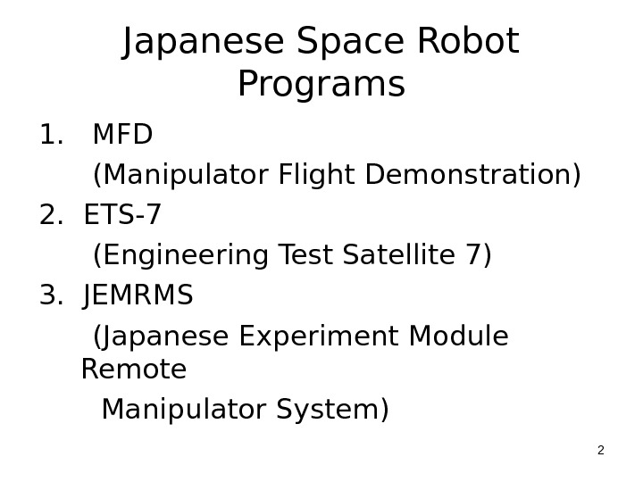
 Japanese Space Robot Programs 1. MFD (Manipulator Flight Demonstration) 2. ETS-7 (Engineering Test Satellite 7) 3. JEMRMS (Japanese Experiment Module Remote Manipulator System)
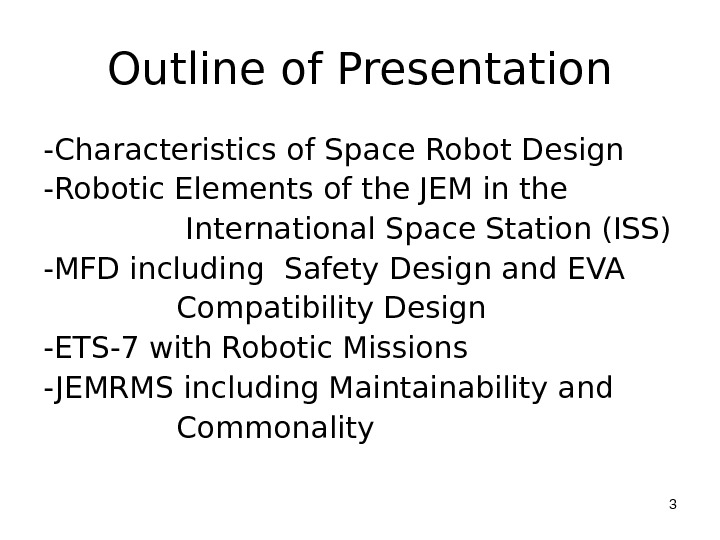
 Outline of Presentation -Characteristics of Space Robot Design -Robotic Elements of the JEM in the International Space Station (ISS) -MFD including Safety Design and EVA Compatibility Design -ETS-7 with Robotic Missions — JEMRMS including Maintainability and Commonality
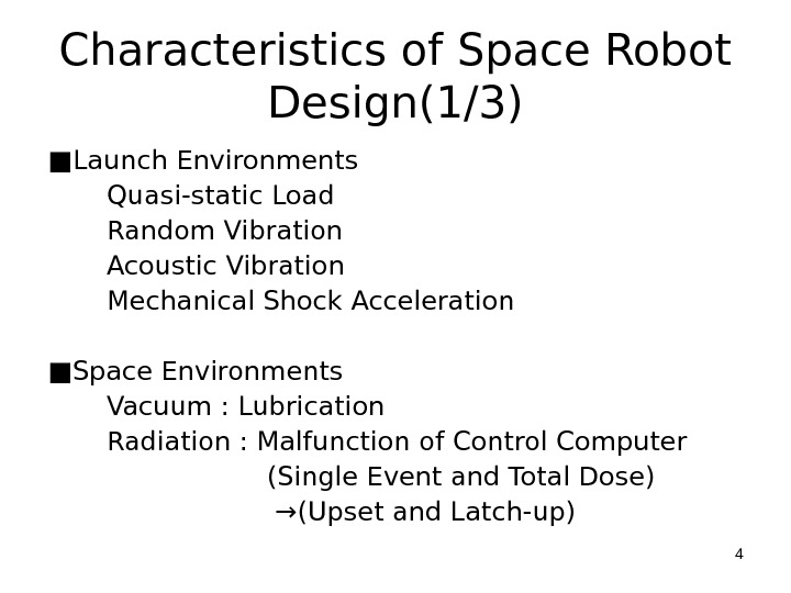
 Characteristics of Space Robot Design(1/3) ■ Launch Environments Quasi-static Load Random Vibration Acoustic Vibration Mechanical Shock Acceleration ■ Space Environments Vacuum : Lubrication Radiation : Malfunction of Control Computer (Single Event and Total Dose) → (Upset and Latch-up)
 Characteristics of Space Robot Design(2/3) Space Debris : Structural Failure, Bamper Weightless Environment : Massive Payload Handling, No Ground Test and Flexibility of the Robot Arm Thermal Cycle : Sunlit/Eclipse and Thermal Expansion (Material Selection)
 Characteristics of Space Robot Design(3/3) Atomic Oxygen Erosion: Degradation of Thermal Surface Nonholonomic System : Depending on the trajectory, the attitude change of spacecraft due to the Robot Arm Motion will be different. ■ Manned Space System Safety Design Consideration: Fault Tolerance Maintainability: EVA (Extravehicular Activities) Compatibility Design Commonality: Human Machine Interface
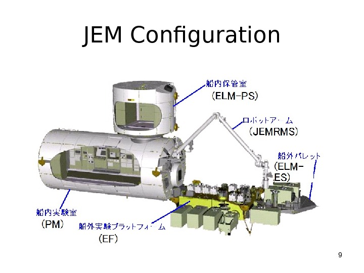
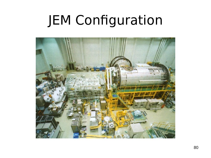
 Robotic Elements of the JEM in the International Space Station(1/3) ■ The Japanese Experiment Module (JEM) is the first Japanese laboratory in space. ■ The JEM Exposed Facility (JEM-EF) is one of the most unique elements not only of the JEM but also of the International Space Station, as an area which is exposed constantly to the space environment.
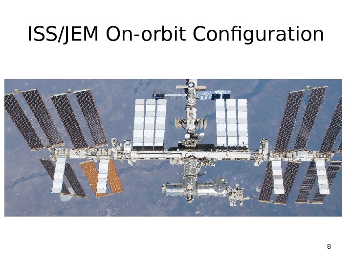
 ISS/JEM On-orbit Configuration
 JEM Configuration
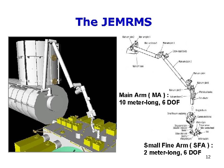
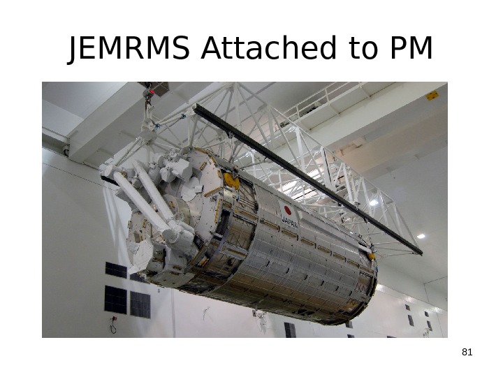
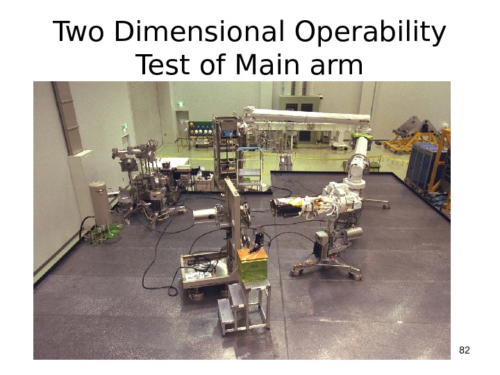
 Robotic Elements of the JEM in the International Space Station(2/3) ■ Replacement or handling of the experiments, materials and Orbital Replacement Units (ORU) mounted on the JEM-EF will be done by a robot arm system (JEM Remote Manipulator System : JEMRMS). ■ The JEMRMS consists of a main arm which is about 10 meters long and a small fine arm which is about 2 meters long and grappled by the main arm in use.
 Robotic Elements of the JEM in the International Space Station(3/3) ■ Both arms have 6 joints (6 degrees-of- freedom) and can move like a human’s arm. ■ Crews in the JEM Pressurized Module operate these arms using hand controllers. ■ The JEMRMS is one of functionally important and technically advanced components of the JEM.

 1. MFD ( M ANIPULATOR F LIGHT D EMONSTRATION)
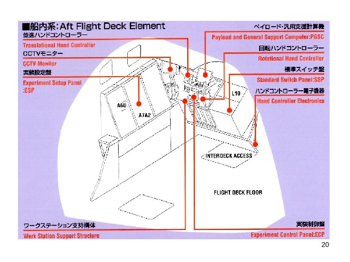
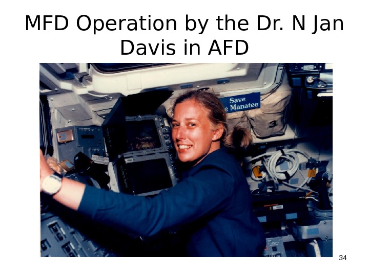
 MFD (Manipulator Flight Demonstration) Experiment (1/2) ■ Manipulator Flight Demonstration was planned to demonstrate the functions and the performances of the Robot Arm similar to the JEMRMS Small Fine Arm using the Space Shuttle prior to JEM launch. ■ The robot arm was installed in the Shuttle Orbiter Payload Bay and operated by IVA crews in the Aft Flight Deck of the Shuttle orbiter using hand controllers.
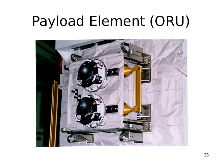
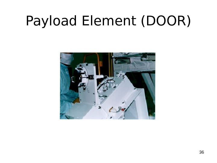
 MFD (Manipulator Flight Demonstration) Experiment (2/2) ■ The functions and the performances of the Robot Arm in the space environment were confirmed, and the Orbital Replacement Unit (ORU) detachment/attachment function and the hinged door open/close function were demonstrated. ■ Also the advanced experiment of the Robot Arm control from the ground was conducted in cooperation with NASA.
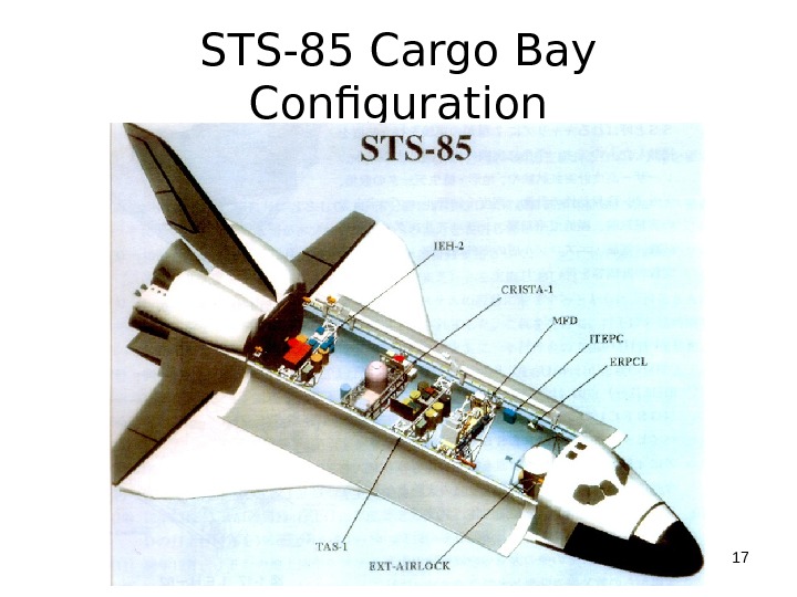
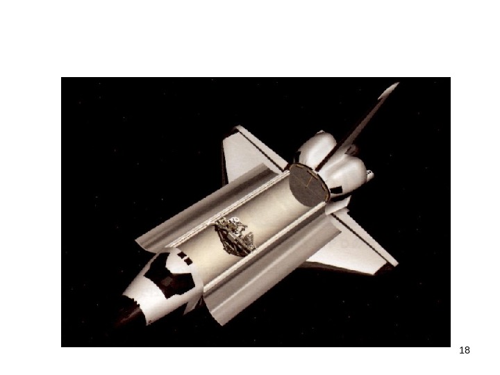
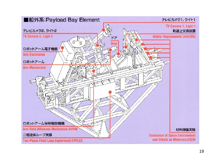
 MFD MISSION ■ STS Launch STS-85 Discovery ■ Launch Date August 7, 1997 GMT ■ Orbit Altitude 270 km ■ Inclination 57 deg ■ Payload Bay Element Mounted on MPESS ■ AFD Element: Robotic Workstation
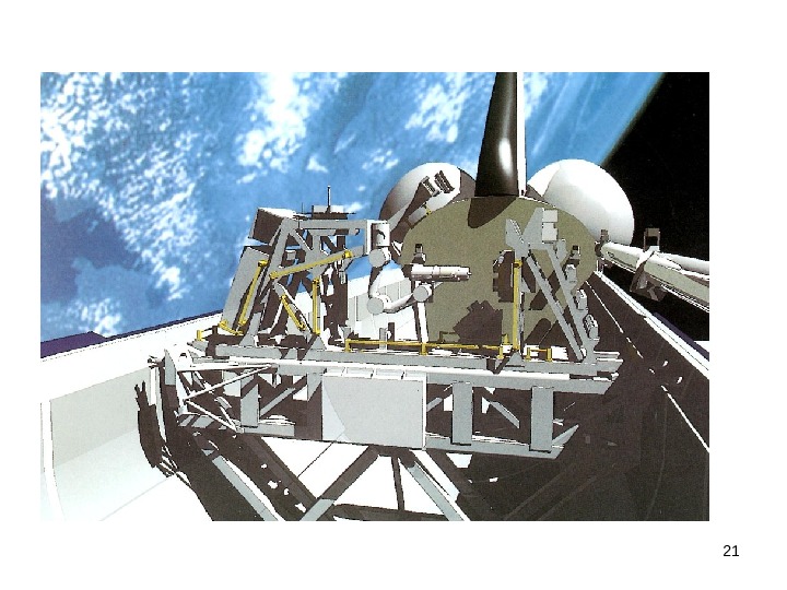
 STS-85 Cargo Bay Configuration


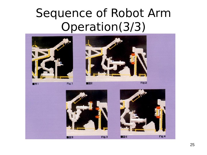
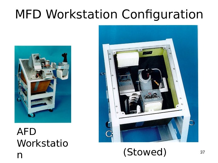
 Sequence of Robot Arm Operation(1/3) ■ The flight test of the Robot Arm was conducted as follows: (1) During the launch the Robot Arm was held by the Arm Hold and Release Mechanism (AHRM). (Fig. 1) (2)Crews assembled the workstation in the Aft Flight Deck, activated the MFD onboard system, released the Robot Arm from the AHRM and Then, performance of the Robot Arm was verified. (Fig. 2)
 Sequence of Robot Arm Operation(2/3) (3) Demonstration of an Orbital Replacement Unit (ORU) detachment/attachment and a Door open/close were conducted, and the functions and performances of the Robot Arm were evaluated. (Figs. 3 and 4) (4)After the completion of the tests by the crew, the NASA ground station sent commands to the Robot Arm through the Shuttle Orbiter to remotely control the Robot Arm.
 Sequence of Robot Arm Operation(3/3) (5)The Robot Arm was held by the AHRM for Shuttle Orbiter return to the earth. (fig. 1) (6)Crews deactivated the MFD onboard system, and disassembled and stowed the workstation in the Aft Flight Deck. ■ EVA compatibility design and its demonstration in the NASA WET
 Sequence of Robot Arm Operation(3/3)
 Safety Design(1/3) ■ The unique nature of the Manned Space System is the Safety Design Consideration. ■ In general Fault Tolerances are the basic design approach to secure the safety. ■ All the hazards are analyzed and the following hazards must be identified: (1)Critical Hazard (2) Catastrophic Hazard
 Safety Design(2/3) (1)Critical Hazard may cause damage to equipment, non-disabling injury, and requires unscheduled safing of orbiter, and affects operations no single failure should result in a critical hazard ==> 2 controls (i. e. , redundant) to prevent critical hazard (1 FT)
 Safety Design(3/3) (2)Catastrophic Hazard: disabling / fatal personal injury, loss of orbiter. No combination of two failures should result in a catastrophic hazard ==> 3 controls (i. e. , dual redundant) to prevent critical hazard (2 FT) Ex) Inadvertent Release of Payload, Collision with other structures or payload
 EVA ■ EVA was one of the means to secure the Payload for Safety Return of the Orbiter. ■ Therefore the EVA could be taken into account as a redundancy. ■ In the case that enough time is not left for securing the Payload Elements, Jettison of the Payload (MPESS) was also available.
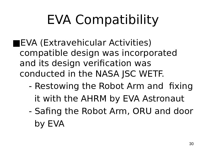
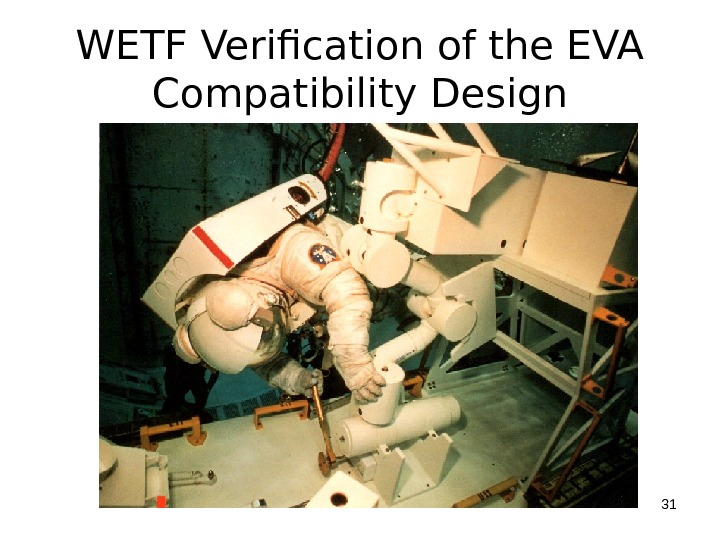
 EVA Compatibility ■ EVA (Extravehicular Activities) compatible design was incorporated and its design verification was conducted in the NASA JSC WETF. — Restowing the Robot Arm and fixing it with the AHRM by EVA Astronaut — Safing the Robot Arm, ORU and door by EV
 WETF Verification of the EVA Compatibility Design
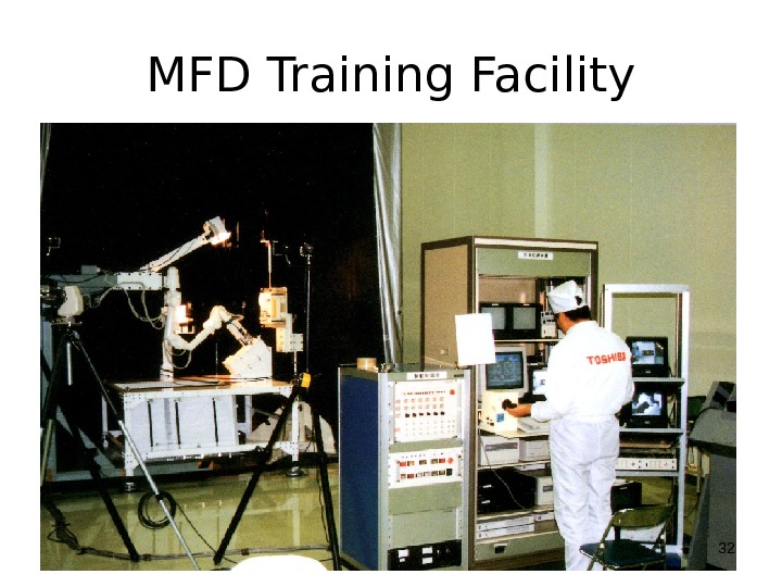
 MFD Training Facility
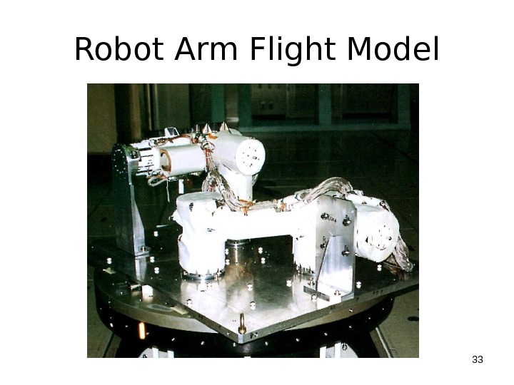
 Robot Arm Flight Model
 MFD Operation by the Dr. N Jan Davis in
 Payload Element (ORU)
 Payload Element (DOOR)
 MFD Workstation Configuration AFD Workstatio n (Stowed)
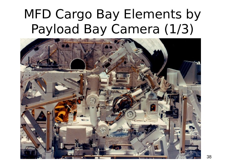
 MFD Cargo Bay Elements by Payload Bay Camera (1/3)
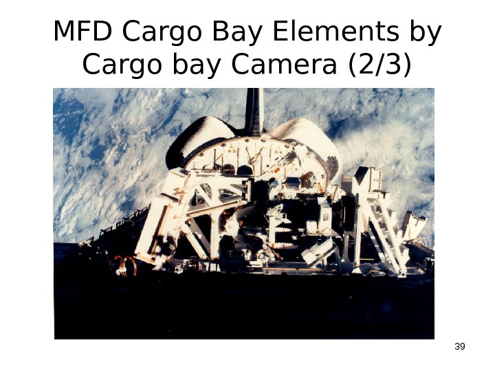
 MFD Cargo Bay Elements by Cargo bay Camera (2/3)
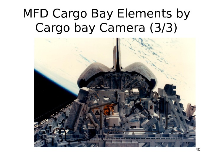
 MFD Cargo Bay Elements by Cargo bay Camera (3/3)
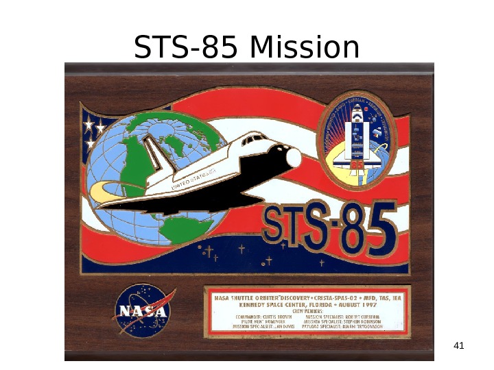
 STS-85 Mission
 2. ETS-7 (Engineering Test Satellite 7)
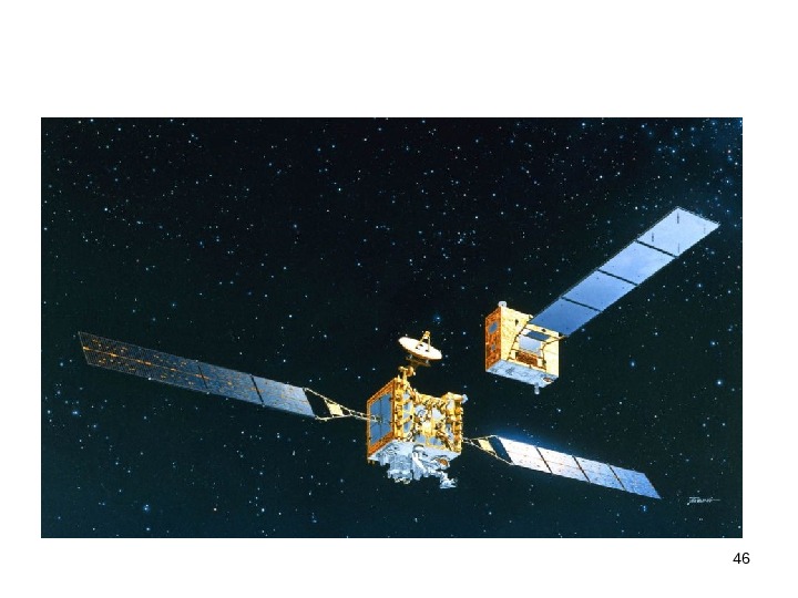
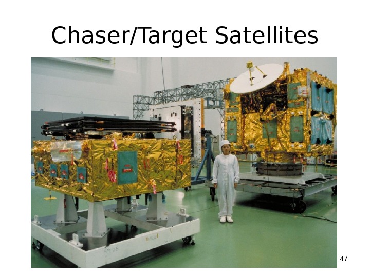
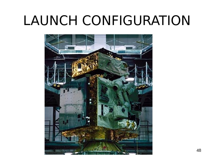
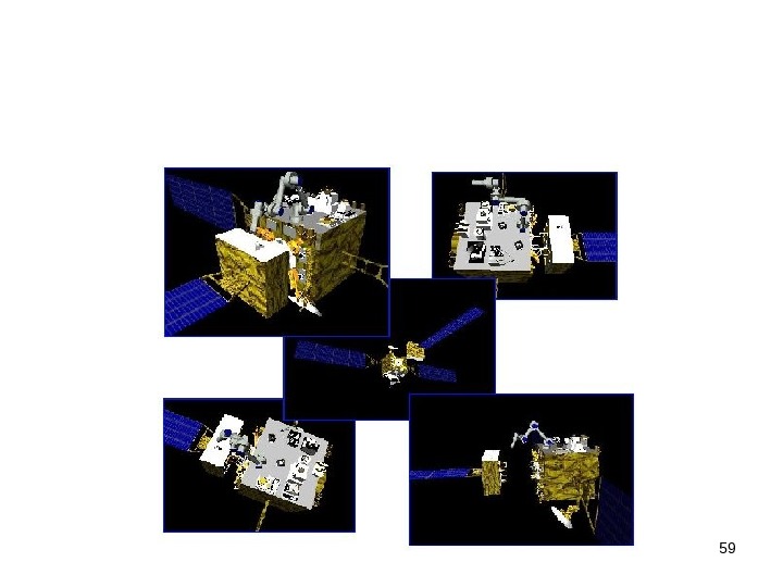
 ETS-7 was launched from Tanegasima launch pad in November 26 1997 by H II-6 Launcher. Two spacecrafts latched together were injected into the orbit and released on orbit. These spacecrafts were chaser and target satellites:
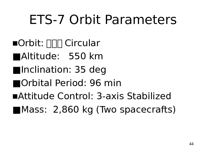
 ETS-7 Orbit Parameters ■ Orbit: Circular ■ Altitude: 550 km ■ Inclination: 35 deg ■ Orbital Period: 96 min ■ Attitude Control: 3 -axis Stabilized ■ Mass: 2, 860 kg (Two spacecrafts)
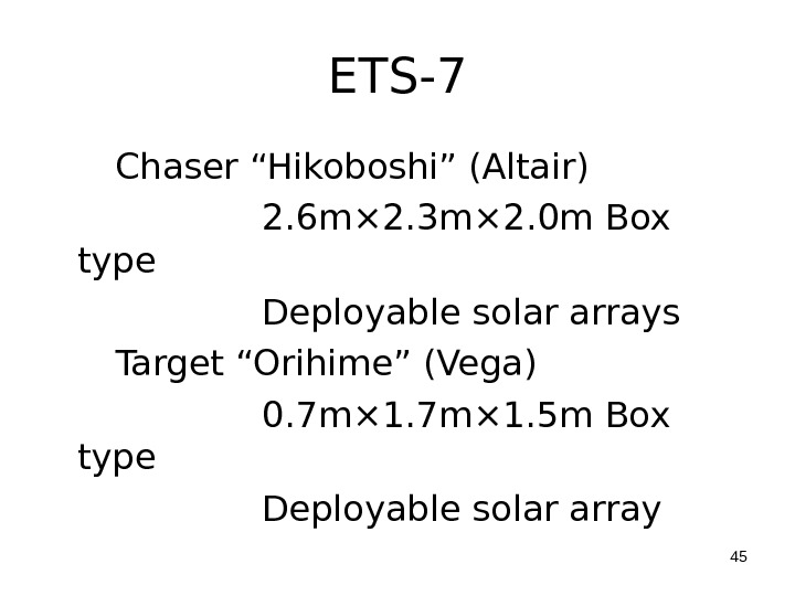
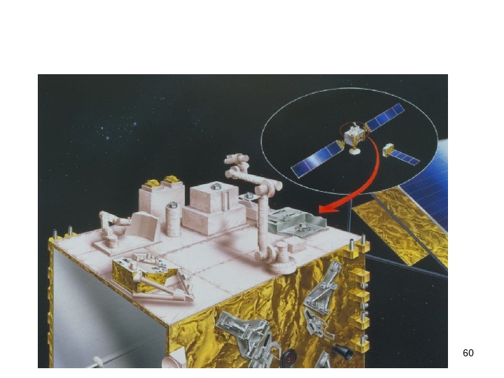
 ETS-7 Chaser “Hikoboshi” (Altair) 2. 6 m× 2. 3 m× 2. 0 m Box type Deployable solar arrays Target “Orihime” (Vega) 0. 7 m× 1. 5 m Box type Deployable solar array

 Chaser/Target Satellites
 LAUNCH CONFIGURATION
 ETS-7 Missions Space Robot Experiments Tele-operation Truss Assembling ORU Handling Refueling dummy propellant
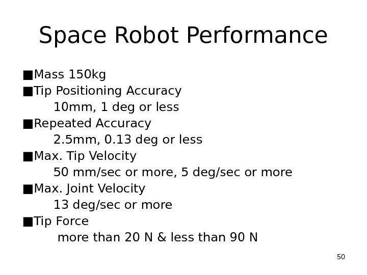
 Space Robot Performance ■ Mass 150 kg ■ Tip Positioning Accuracy 10 mm, 1 deg or less ■ Repeated Accuracy 2. 5 mm, 0. 13 deg or less ■ Max. Tip Velocity 50 mm/sec or more, 5 deg/sec or more ■ Max. Joint Velocity 13 deg/sec or more ■ Tip Force more than 20 N & less than 90 N
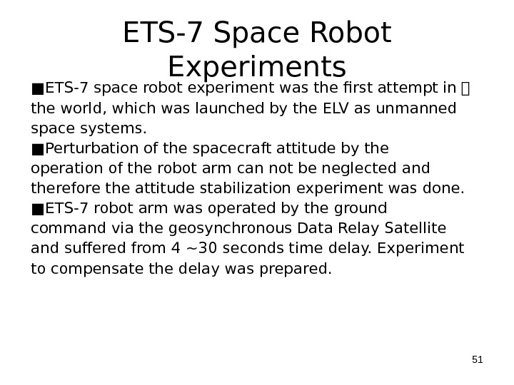
 ETS-7 Space Robot Experiments ■ ETS-7 space robot experiment was the first attempt in the world, which was launched by the ELV as unmanned space systems. ■ Perturbation of the spacecraft attitude by the operation of the robot arm can not be neglected and therefore the attitude stabilization experiment was done. ■ ETS-7 robot arm was operated by the ground command via the geosynchronous Data Relay Satellite and suffered from 4 ~30 seconds time delay. Experiment to compensate the delay was prepared.
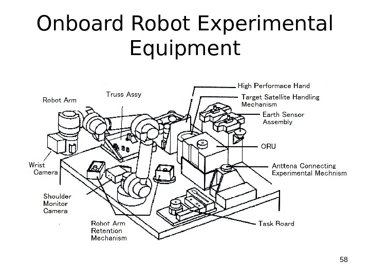
 System Elements of Space Robot Experiment(1/6) (1) Robot Arm 6 degrees of freedom Approximately 2 m long Each joint is driven by DC brushless motor with harmonic drive gear. Control mode 1) Joint position/Rate control mode 2) Cartesian position/Rate Control mode 3) Cartesian compliance control mode
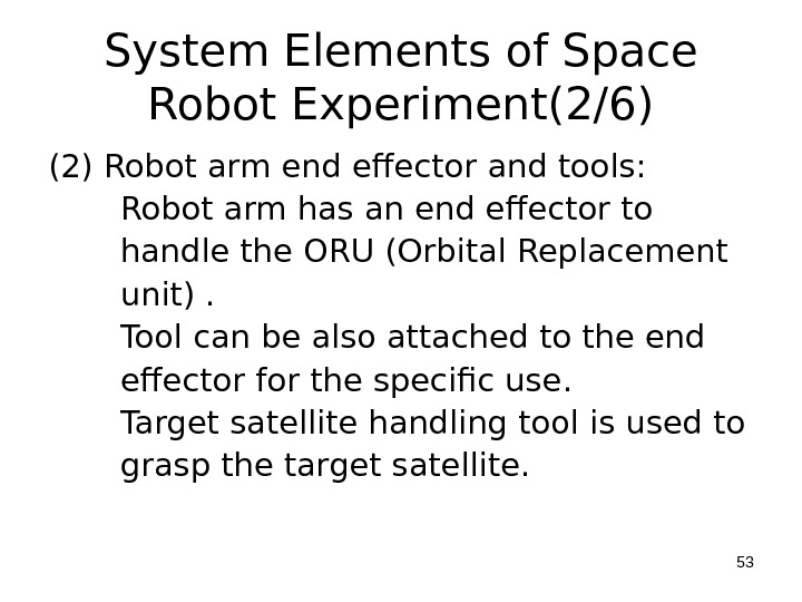
 System Elements of Space Robot Experiment(2/6) (2) Robot arm end effector and tools: Robot arm has an end effector to handle the ORU (Orbital Replacement unit). Tool can be also attached to the end effector for the specific use. Target satellite handling tool is used to grasp the target satellite.
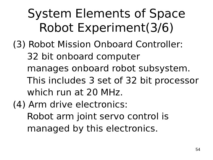
 System Elements of Space Robot Experiment(3/6) (3) Robot Mission Onboard Controller: 32 bit onboard computer manages onboard robot subsystem. This includes 3 set of 32 bit processor which run at 20 MHz. (4) Arm drive electronics: Robot arm joint servo control is managed by this electronics.
 System Elements of Space Robot Experiment(4/6) (5) ORU Experimental ORU is mounted on the robot experiment platform. Grasping, removing and restoring operations are done. A fuel supply experiment is done to demonstrate a liquid QD(Quick Disconnect) for the fuel transfer.
 System Elements of Space Robot Experiment(5/6) (6) Taskboard is used for evaluation of the robot arm performance. The taskboard consists of Force Torque Sensor Calibration mechanism, Peg-in- hole mechanism, slide handle and others.
 System Elements of Space Robot Experiment(6/6) (7) Vision System A pair of Arm Hand Camera are mounted on the robot arm endeffector and used to measure attitude and distance between the robot arm and payloads. Also a pair of Arm monitor camera are mounted to observe robot arm motion. The above pairs of cameras can produce the stereoscopic images.
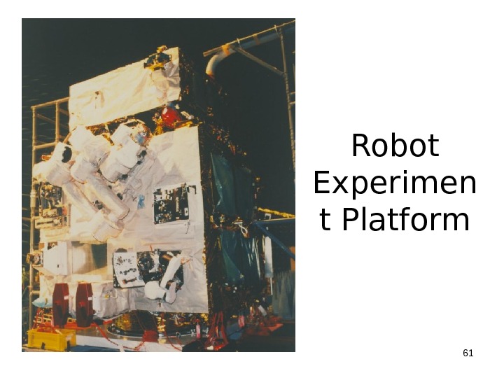
 Onboard Robot Experimental Equipment


 Robot Experimen t Platform
 3. JEMRMS (Japanese Experiment Module Remote Manipulator System)
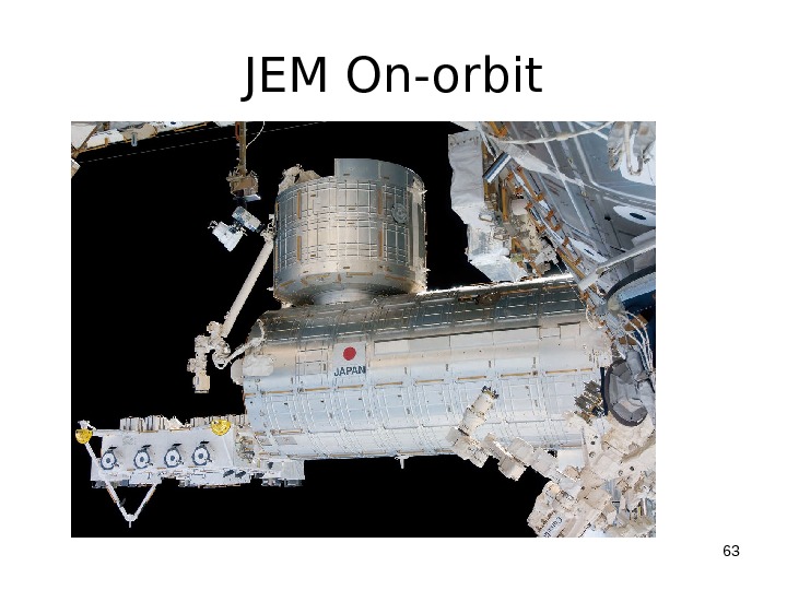
 JEM On-orbit
 JEMRMS ■ The JEMRMS (JEM Remote Manipulator System) is remotely manipulated system to reduce the crew EVA (Extravehicular Activities) task and its work loads. ■ The following tasks are performed by JEMRMS: -Berthing of JEM Elements -Exchange of Payloads and ORU (Orbital Replacement Unit) on the Experimental Platform (EF) -Support of Experiments -Maintenance Tasks
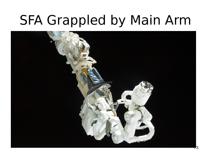
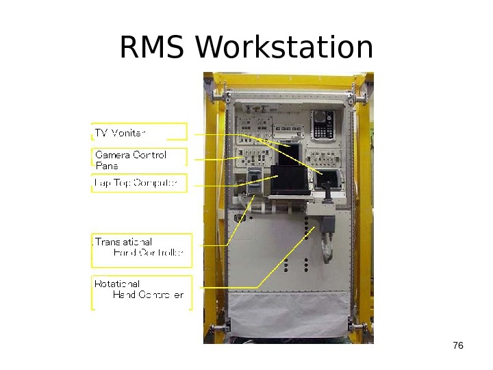
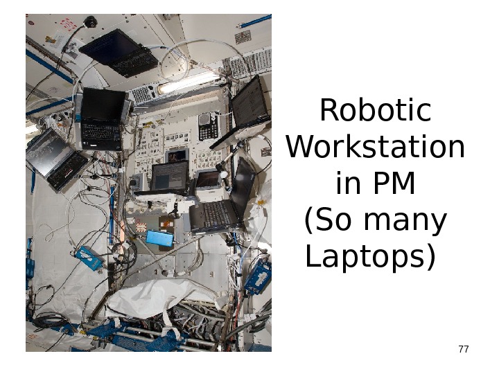
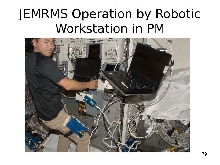
 JEMRMS ■ Main Elements of JEMRMS -a main arm, -a small fine arm (SFA) which is grappled by the main arm Endeffector and -RMS Console in PM.
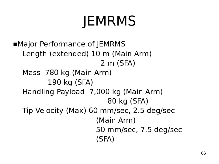
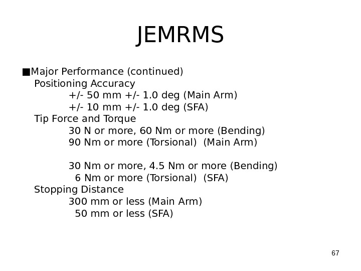
 JEMRMS ■ Major Performance of JEMRMS Length (extended) 10 m (Main Arm) 2 m (SFA) Mass 780 kg (Main Arm) 190 kg (SFA) Handling Payload 7, 000 kg (Main Arm) 80 kg (SFA) Tip Velocity (Max) 60 mm/sec, 2. 5 deg/sec (Main Arm) 50 mm/sec, 7. 5 deg/sec (SFA)
 JEMRMS ■ Major Performance (continued) Positioning Accuracy +/- 50 mm +/- 1. 0 deg (Main Arm) +/- 10 mm +/- 1. 0 deg (SFA) Tip Force and Torque 30 N or more, 60 Nm or more (Bending) 90 Nm or more (Torsional) (Main Arm) 30 Nm or more, 4. 5 Nm or more (Bending) 6 Nm or more (Torsional) (SFA) Stopping Distance 300 mm or less (Main Arm) 50 mm or less (SFA)
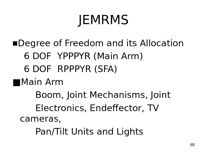
 JEMRMS ■ Degree of Freedom and its Allocation 6 DOF YPPPYR (Main Arm) 6 DOF RPPPYR (SFA) ■ Main Arm Boom, Joint Mechanisms, Joint Electronics, Endeffector, TV cameras, Pan/Tilt Units and Lights
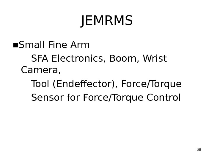
 JEMRMS ■ Small Fine Arm SFA Electronics, Boom, Wrist Camera, Tool (Endeffector), Force/Torque Sensor for Force/Torque Control
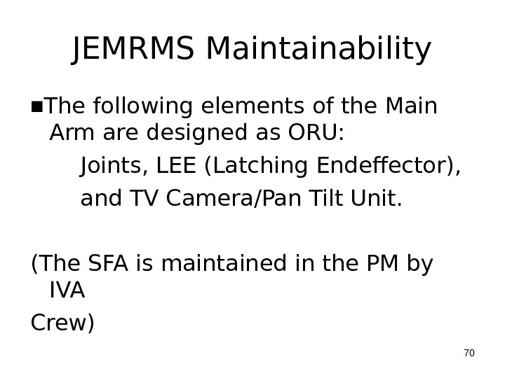
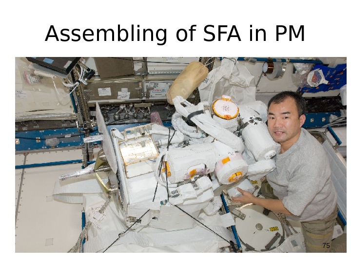
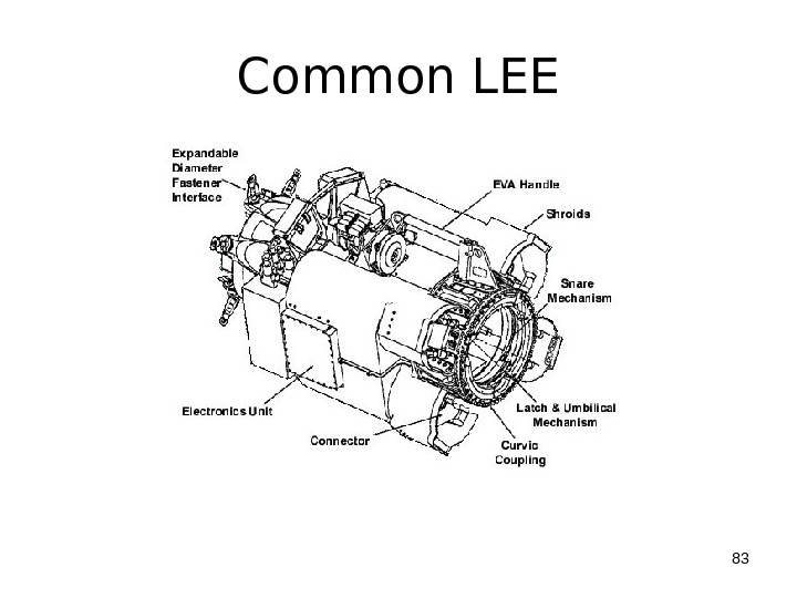
 JEMRMS Maintainability ■ The following elements of the Main Arm are designed as ORU: Joints, LEE (Latching Endeffector), and TV Camera/Pan Tilt Unit. (The SFA is maintained in the PM by IVA Crew)
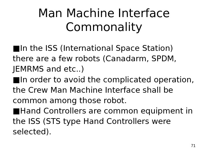
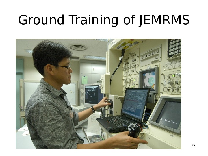
 Man Machine Interface Commonality ■ In the ISS (International Space Station) there a few robots (Canadarm, SPDM, JEMRMS and etc. . ) ■ In order to avoid the complicated operation, the Crew Man Machine Interface shall be common among those robot. ■ Hand Controllers are common equipment in the ISS (STS type Hand Controllers were selected).
 JEMRMS Main Arm Operation
 SFA Grappled by Main Arm
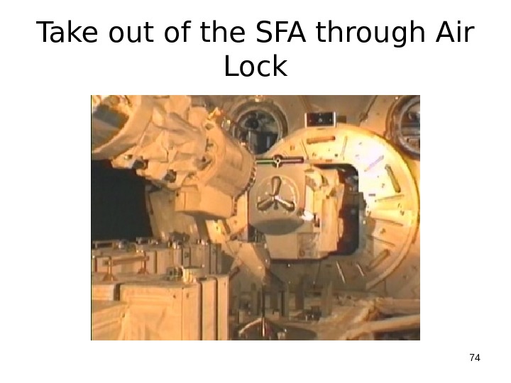
 Take out of the SFA through Air Lock
 Assembling of SFA in PM
 RMS Workstation
 Robotic Workstation in PM (So many Laptops)
 Ground Training of JEMRMS
 JEMRMS Operation by Robotic Workstation in PM
 JEM Configuration
 JEMRMS Attached to PM
 Two Dimensional Operability Test of Main arm
 Common L
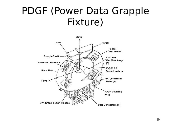
 PDGF (Power Data Grapple Fixture)
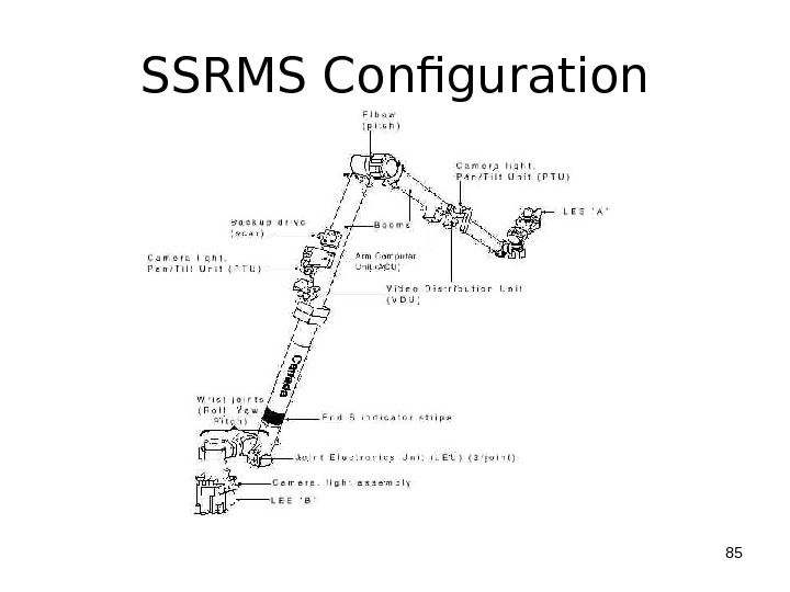
 SSRMS Configuration
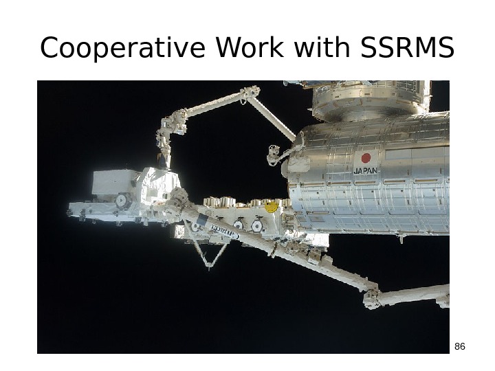
 Cooperative Work with SSRMS
 Summary ■ In summary the Space Robot Development in Japan has been successful so far. ■ A lot of experimental results have been obtained for unmanned and manned Space Robot Systems. ■ Future application of the above result will be expected.

