

dcbffa243353543abb7e591597010d34.ppt
- Количество слайдов: 29
 Agenda – Day 1 8: 00 am – 8: 15 am – 8: 45 am – 9: 30 am – 9: 45 am – 11: 45 am – 12: 00 pm – 1: 00 pm – 2: 30 pm – 2: 45 pm – 3: 45 pm – 4: 00 pm Introductions and House Keeping Session 1: Load Rating Basics Session 2: Basic Load Rating Calculations Break Session 3: Example – Load Rating Concrete Slab Bridge Questions Lunch Session 4: Example – Load Rating Steel Beam Bridges Break Session 4: Example – Load Rating Steel Beam Bridges (Con’t) Questions Load Rating Seminar 1
 • Dead Load Calculations") Session 2: Basic Load Rating Calculations • Capacity Calculations (C) • Dead Load Calculations (DL) • Live Load Calculations (LL + I) • Rating Factor (RF) LFR: RF = Capacity – A 1 (DL) A 2 (LL + I)
Session 2: Basic Load Rating Calculations • Capacity Calculations (C) • Dead Load Calculations (DL) • Live Load Calculations (LL + I) • Rating Factor (RF) LFR: RF = Capacity – A 1 (DL) A 2 (LL + I)
 depends on material, shape, & Condition • Generally for") Capacity Calculations • Capacity (C) depends on material, shape, & Condition • Generally for normal bridges, bending controls the load rating of the bridge. • Section loss at beam ends may make shear or bearing control the bridge capacity • Examples will show to calculate C
Capacity Calculations • Capacity (C) depends on material, shape, & Condition • Generally for normal bridges, bending controls the load rating of the bridge. • Section loss at beam ends may make shear or bearing control the bridge capacity • Examples will show to calculate C
 Capacity Calculations • What to do when you don’t know material properties • ODOT BDM Figures 904 and 905 give material properties based on year built. • Be careful during transition years. • See Appendix A
 Capacity Calculations • What to do when you don’t know Section properties • Steel Members: • AISC Manual of Steel Construction give section properties • See Appendix B for section properties for shapes rolled between 1873 and 1952 (Thank you B&N) • Measure the beams in the field – beam depth, flange width, web thickness, flange thickness (be careful with I and S shapes – bottom flanges are sloped)
 Capacity Calculations • What to do when you don’t know Section properties • Concrete Members: • Need to know reinforcing steel in member. • Reinforcing steel can come from bridge plans, design data sheet, or standard drawing. • If don’t know the reinforcing steel in member, then “engineering judgment” is acceptable.
 Dead Load Calculations • Many bridges – DL can be applied as a uniform load (w k/ft) • Cross frames • Steel guardrail • Standard references are available for unit weights for example: • Concrete = 150 lb/cf • Steel = 490 lb/cf • Asphalt = 144 lb/cf
 Dead Load Calculations • Do not include Future Wearing Surface in this calculation. Only include the dead load that is currently on the bridge. • Any superimposed dead load that is placed after deck is poured, may be distributed to all beams. An example would be railing. • Moment (M) for uniform load: M = w. L 2/8 w = uniform load (k/ft. ) L = length of beam (ft. )
 Dead Load Calculations • If Dead Load includes concentrated items calculate dead load moment via shear and moment diagrams. • Diaphrams on pre-stressed box beams
 A 2 (LL +") Dead Load Calculations RF = Capacity – A 1 (DL) A 2 (LL + I) Rating Type A 1 = Factor for A 2 = Factor for live load Inventory 1. 3 * Design level Operating 1. 3 2. 17 dead loads 1. 3 Ref: AASHTO Manual for Condition Evaluation of Bridges 1994 Load Rating Seminar 10
Dead Load Calculations RF = Capacity – A 1 (DL) A 2 (LL + I) Rating Type A 1 = Factor for A 2 = Factor for live load Inventory 1. 3 * Design level Operating 1. 3 2. 17 dead loads 1. 3 Ref: AASHTO Manual for Condition Evaluation of Bridges 1994 Load Rating Seminar 10
 Live Load Calculations • Items to discuss • Shear and Moment diagrams • Live load moment equations • Live load distribution factors • Wheel vs. Axle • Impact factor
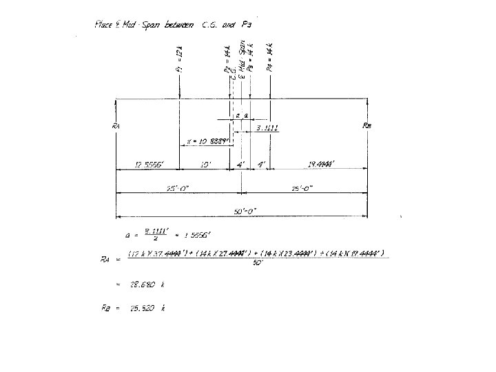
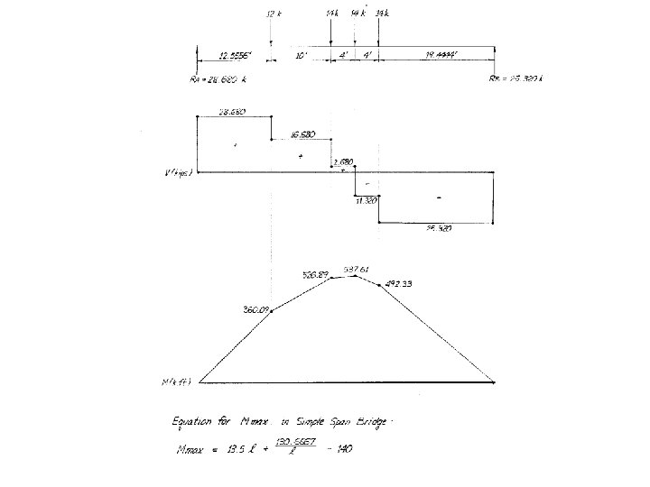
 Live Load Calculations • Shear and Moment Calculations • Sample set of calculations to determine maximum moment for a 4 F 1 truck • Moment from any truck configuration can be determined this way
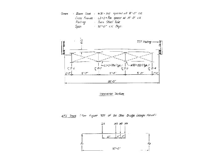
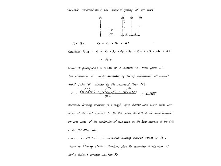
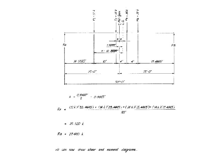
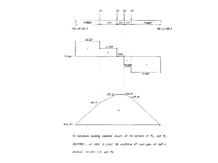
 Live Load Calculations • Live Load Moment Calculations • See Appendix C for live load moment equations for the Ohio load rating trucks. • These are axle (full truck) live load moments
 • How much truck is") Live Load Calculations • Live Load Distribution Factors (LLDF) • How much truck is carried by each beam or strip of slab. • One Axle = 2 wheels • Be careful with wheel vs. axle • Be consistent with LLDF and Live load moment • See Section 3. 23 AASHTO Standard Specifications for Highway Bridges for wheel live load distribution factors.
Live Load Calculations • Live Load Distribution Factors (LLDF) • How much truck is carried by each beam or strip of slab. • One Axle = 2 wheels • Be careful with wheel vs. axle • Be consistent with LLDF and Live load moment • See Section 3. 23 AASHTO Standard Specifications for Highway Bridges for wheel live load distribution factors.
 - Examples • Longitudinal interior") Live Load Calculations § Live Load Distribution Factors (LLDF) - Examples • Longitudinal interior steel or concrete beam w/ concrete deck and two or more lanes on bridge • LLDF (wheel) = S / 5. 5 S = average beam spacing • Longitudinal interior steel or concrete beam w/ 4 in. thick wooden deck and two or more lanes on bridge • LLDF (wheel) = S / 4. 0 S = average beam spacing
Live Load Calculations § Live Load Distribution Factors (LLDF) - Examples • Longitudinal interior steel or concrete beam w/ concrete deck and two or more lanes on bridge • LLDF (wheel) = S / 5. 5 S = average beam spacing • Longitudinal interior steel or concrete beam w/ 4 in. thick wooden deck and two or more lanes on bridge • LLDF (wheel) = S / 4. 0 S = average beam spacing
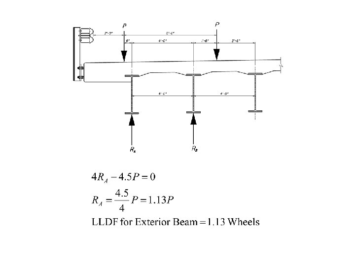
 • Exterior steel or concrete") Live Load Calculations • Live Load Distribution Factors (LLDF) • Exterior steel or concrete beams: • Place wheel load 2 ft. from face of guardrail • Assume deck acts as simple span • Calculate the Reaction of the wheel load
Live Load Calculations • Live Load Distribution Factors (LLDF) • Exterior steel or concrete beams: • Place wheel load 2 ft. from face of guardrail • Assume deck acts as simple span • Calculate the Reaction of the wheel load
 Live Load Distribution Factor – Exterior Beam
 I = 50 L +") Live Load Calculations • Live Load Impact Factor (I) I = 50 L + 125 I Maximum = 30 % L = length of loaded span L = span length for simple spans
Live Load Calculations • Live Load Impact Factor (I) I = 50 L + 125 I Maximum = 30 % L = length of loaded span L = span length for simple spans
 – Example Beam is 55") Live Load Calculations • Live Load Impact Factor (I) – Example Beam is 55 ft. long L= 55 I = 50 / (125 + 55) I = 0. 28 = 28 % < 30 % I = 28 % Multiply the Live Load Moment by 1. 28
Live Load Calculations • Live Load Impact Factor (I) – Example Beam is 55 ft. long L= 55 I = 50 / (125 + 55) I = 0. 28 = 28 % < 30 % I = 28 % Multiply the Live Load Moment by 1. 28
 A 2 (LL +") Live Load Calculations RF = Capacity – A 1 (DL) A 2 (LL + I) Rating Type A 1 = Factor for A 2 = Factor for live load Inventory 1. 3 * Design level Operating 1. 3 2. 17 dead loads 1. 3 Ref: AASHTO Manual for Condition Evaluation of Bridges 1994 Load Rating Seminar 27
Live Load Calculations RF = Capacity – A 1 (DL) A 2 (LL + I) Rating Type A 1 = Factor for A 2 = Factor for live load Inventory 1. 3 * Design level Operating 1. 3 2. 17 dead loads 1. 3 Ref: AASHTO Manual for Condition Evaluation of Bridges 1994 Load Rating Seminar 27
 to: • Percent Legal Load (Legal") Rating Factor Calculations • Converting Rating Factor (RF) to: • Percent Legal Load (Legal Load Vehicles) • RF X 100 = % Legal Load • Tons (Legal Load Vehicles) • RF X # tons of Truck used (GVW in tons) • For 5 C 1 Truck (GVW = 40 tons) with a RF = 1. 23 • Load Rating Tons = 1. 23 X 40 = 49 tons • HS Rating (HS 20 truck used) • RF X 20 = HS rating • RF = 1. 56 then 1. 56 X 20 = HS 31. 2
Rating Factor Calculations • Converting Rating Factor (RF) to: • Percent Legal Load (Legal Load Vehicles) • RF X 100 = % Legal Load • Tons (Legal Load Vehicles) • RF X # tons of Truck used (GVW in tons) • For 5 C 1 Truck (GVW = 40 tons) with a RF = 1. 23 • Load Rating Tons = 1. 23 X 40 = 49 tons • HS Rating (HS 20 truck used) • RF X 20 = HS rating • RF = 1. 56 then 1. 56 X 20 = HS 31. 2
 Questions ? ?