b1ad69ba85dfb0a4c84739749ddc48f5.ppt
- Количество слайдов: 200


AE 2401 AVIONICS Notes of Lesson Prepared by, Magesh Mani, Lecturer, Aeronautical Department, Rajalakshmi Engineering College

UNIT -I


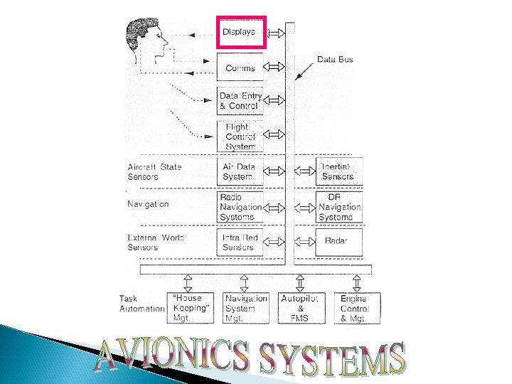
Combination of aviation and electronics Avionics system or Avionics sub-system dependent on electronics Avionics industry- a major multi-billion dollar industry world wide Avionics equipment on a modern military or civil aircraft account for around Ø 30% of the total cost of the aircraft Ø 40% in the case of a maritime patrol/anti-submarine aircraft (or helicopter) Ø Over 75% of the total cost in the case of an airborne early warning aircraft Ø such as an AWACS

To enable the flight crew to carry out the aircraft mission safely and efficiently Mission is carrying passengers to their destination (Civil Airliner) Intercepting a hostile aircraft, attacking a ground target, reconnaissance or maritime patrol (Military Aircraft)

To meet the mission requirements with the minimum flight crew (namely the first pilot and the second pilot) Economic benefits like Saving of crew salaries Expenses and training costs Reduction in weigh-more passengers or longer range on less fuel
 aircraft is")
IN THE MILITARY CASE ü A single seat fighter or strike (attack) aircraft is lighter ü Costs less than an equivalent two seat version ü ü Elimination of the second crew member (navigator/observer/crew member) Reduction in training costs

OTHER VERY IMPORTANT DRIVERS FOR AVIONICS SYSTEMS ARE Increased safety Air traffic control requirements All weather operation Reduction in fuel consumption Improved aircraft performance and control and handling and reduction in maintenance costs * In the military case, the avionics systems are also being driven by a continuing increase in the threats posed by the

AVIONICS SYSTEM REQUIREMENTS

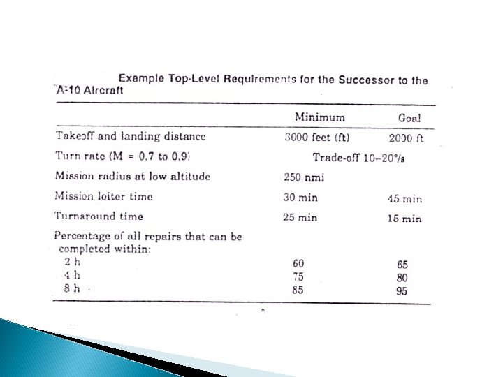
Avionics System Design Starting point for designing a digital Avionics system is a clear understanding of the mission requirements and the requirement levied by the host aircraft Top-level Requirement for Military ◦ The customer prepares the statement of need and top-level description of possible missions ◦ Describes the gross characteristic of a hypothetical aircraft that could fly the mission ◦ Customer may also describe the mission environment and define strategic and tactical philosophies and principles and rules of engagement.

PRELIMINARY THOUGHTS ON DESIGN Design is, in general, ◦ ◦ ◦ a team effort a large system integration activity done in three stages iterative creative, knowledge based. The three stages are: ◦ Conceptual design ◦ Preliminary design ◦ Detailed design

DOD-STD-2167 A System Development Cycle

Aircraft Mission Requirements to Avionics System Requirements

Conceptual Design What will it do? How will it do it? What is the general arrangement of parts? The end result of conceptual design is an artist’s or engineer’s conception of the vehicle/product. Example: Clay model of an automobile.

Conceptual Designs Dan Raymer sketch

Conceptual Designs 1988 Lockheed Desig

Preliminary Design How big will it be? How much will it weigh? What engines will it use? How much fuel or propellent will it use? How much will it cost? This is what you will do in this course.

Preliminary Design Analysis www. aero-siam. com/S 405 -Wing. Design

Detailed Design How many parts will it have? What shape will they be? What materials? How will it be made? How will the parts be joined? How will technology advancements (e. g. lightweight material, advanced airfoils, improved engines, etc. ) impact the design?

Detailed Design Dassault Systems - CATIA

Detailed Design Dassault Systems - CATIA

Detailed Design Dassault Systems - CATIA

A 380 Arrangement

SPECIFICATION AND STANDARDS The designer needs to satisfy ◦ Customer who will buy and operate the vehicle (e. g. Delta, TWA) ◦ Government Regulators (U. S. , Military, European, Japanese…)

CUSTOMER SPECIFICATIONS Performance: ◦ Payload weight and volume ◦ how far and how fast it is to be carried ◦ how long and at what altitude ◦ passenger comfort ◦ flight instruments, ground and flight handling qualities Cost Price of system and spares, useful life, maintenance hours per flight hour Firm order of units, options, Delivery schedule, payment schedule

TYPICAL GOVERNMENT STANDARDS Civil ◦ FAA Civil Aviation Regulations define such things as required strength, acoustics, effluents, reliability, take-off and landing performance, emergency egress time. Military ◦ May play a dual role as customer and regulator ◦ MIL SPECS (Military specifications) ◦ May set minimum standards for Mission turnaround time, strength, stability, speed-altitudemaneuver capability, detectability, vulnerability

SYSTEM INTEGRATION Aircraft/Spacecraft Design often involves integrating parts, large and small, made by other vendors, into an airframe or spaceframe (also called “the bus. ”) Parts include ◦ engines, landing gear, shock absorbers, wheels, brakes, tires ◦ avionics (radios, antennae, flight control computers) ◦ cockpit instruments, actuators that move control surfaces, retract landing gears, etc. . .

A 380 Production

AEROSPACE DESIGN INVOLVES Lot of Analyses Ground testing and simulation (e. g. wind tunnel tests of model aircraft, flight simulation, drop tests, full scale mock-up, fatigue tests) Flight tests

Top-level Requirement for Civil Aircraft The aircraft manufacturer makes a very careful analysis of the potential customer’s route structure, image , and operating philosophies to determine the customer’s need and postulates a future operating environment. The manufacturer then designs an aircraft that provides an optimum, balance response to the integrated set of needs Safety is always the highest priority need and economical operation is a close second.

Requirements of MIL-F-9490 Five operational States for the flight control system: ◦ ◦ Operational State I: Normal Operational State II: Restricted Operational State I: Minimum safe Operational State I: Controllable to an immediate emergency landing ◦ Operational State I: Controllable to an evacuable flight condition

Criticality Classification Definitions 9490 Essential : A function is essential if it’s loss degrades the flight control system beyond operational state III. Flight Phase Essential : Same as essential except it applies only during specific flight phases. Non-Critical : Loss of function does not effect flight safety or reduce control capability beyond that required for operation state III

Probability of failures –FAR 25. 1309

“Ilities” of Avionics System
 Availability")
Major Ilities of Avionics System • • • Capability Reliability Maintainability Certificability Survivability(military) Availability Susceptibility vulnerability Life cycle cost(military) or cost of ownership(civil) Technical risk Weight & power

• Capability: – How capable is avionics system? – can they do the job and even more? – Designer to maximize the capability of the system within the constraints that are imposed. • Reliability: – Designer strives to make systems as reliable as possible. – High reliability less maintenance costs. – If less reliable customer will not buy it and in terms of civil airlines the certificating agencies will not certify it.

• Maintainability: – Closely related to reliability – System must need preventive or corrective maintenance. – System can be maintained through built in testing, automated troubleshooting and easy access to hardware. • Availability: – Combination of reliability and maintainability – Trade of between reliability and maintainability to optimize availability. – Availability translates into sorties for military aircraft and into revenue flights for civil aircrafts.

Certificability: ◦ Major area of concern for avionics in civil airlines. ◦ Certification conducted by the regulatory agencies based on detailed, expert examination of all facets of aircraft design and operation. ◦ The avionics architecture should be straight forward and easily understandable. ◦ There should be no sneak circuits and no noobvious modes of operation. ◦ Avionics certification focus on three analyses: preliminary hazard, fault tree, and FMEA.

• Survivability: – It is a function of susceptibility and vulnerability. – Susceptibility: measure of probability that an aircraft will be hit by a given threat. – Vulnerability: measure of the probability that damage will occur if there is a hit by the threat • Life cycle ownership: cost(LCC)or Cost of • It deals with economic measures need for evaluating avionics architecture. • It includes costs of varied items as spares acquisition, transportation, storage and training (crew and Maintenance personnel's), hardware development and test, depreciation and interest.

• Risk: – Amount of failures and drawbacks in the design and implementation. – Over come by using the latest technology and fail proof technique to overcome both developmental and long term technological risks. • Weight and power: – Minimize the weight and power requirements are two fundamental concepts of avionics design. – So the design must be light weight and power consuming which is possible through the data bus and latest advancement of electronics devices.
 ECM")
Integrated Avionics weapon systems SONAR RADAR Military communications Electro optics (FLIR or PIDS) ECM OR ECCM ESM/DAS Tactical missile guidance

UNIT - II

Intel 8085 Microprocessors

Introduction: Microprocessor is a programmable integrated device that has computing and decision-making capability similar to that of the central processing unit of the computer. It is a multipurpose, programmable, clock-driven, register-based electronic device that reads binary instructions from a storage device called memory, accepts binary data as input and processes data according to those instructions, and provide results as output. Memory Micro Processor Input Output

Continued…. . Whereas Microcontroller that include all the components shown in the previous figure on one chip. Examples include a wide range of products such as washing machines, dishwashers, traffic light controllers, and automatic testing instruments.

Components of Microprocessor

Internal Architecture of Microprocessor

Microprocessor controlled temperature system

Generation of Microprocessors

Introduction » » » 8 -bit microprocessor Up to 8 MHz 64 KB RAM Single voltage On-chip peripherals 256 I/O ports 8080 object-code compatible Produced: From 1977 to 1990 s Common manufacturer(s): Intel and several others Instruction set: pre x 86 Package(s): 40 pin DIP (Dual in-line package)

Companies Manufacturing 8085
 2 - 3. 1 3")
Commparison with 8080 Features 8080 8085 Processor speed (MHz) 2 - 3. 1 3 - 6 Power supply +5 V, -5 V and +12 V +5 V On-chip peripherals Clock oscillator system controller Serial I/O lines Address/Data bus Separate address and data busses Multiplexed address and data Pins/signals Reset Out pin RD bus signal WR bus signal IO/M bus signal ALE pin provides encoded bus status information Interrupts Three maskable interrupts and one non -maskable Instruction set RIM - read interrupt mask SIM - Set interrupt mask

Pin Diagram
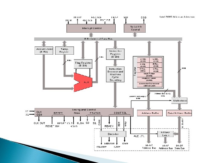

Internal Registers and Flags of 8085 A

Registers Accumulator or A register is an 8 -bit register used for arithmetic, logic, I/O and load/store operations. Flag is an 8 -bit register containing 5 1 -bit flags: ◦ ◦ ◦ Sign - set if the most significant bit of the result is set. Zero - set if the result is zero. Auxiliary carry - set if there was a carry out from bit 3 to bit 4 of the result. Parity - set if the parity (the number of set bits in the result) is even. Carry - set if there was a carry during addition, or borrow during subtraction/comparison. Stack pointer is a 16 bit register. , it points to a memory location in R/W memory canned the stack. The beginning of stack is defined by loading the 16 bit address in the stack pointer. Program counter is a 16 -bit register, it points to the memory address from which the next byte is to be fetched, when the next byte is fetched the counter is incremented by one and point to next location.

Registers General registers: ◦ 8 -bit B and 8 -bit C registers can be used as one 16 -bit BC register pair. When used as a pair the C register contains low-order byte. Some instructions may use BC register as a data pointer. ◦ 8 -bit D and 8 -bit E registers can be used as one 16 -bit DE register pair. When used as a pair the E register contains low-order byte. Some instructions may use DE register as a data pointer. ◦ 8 -bit H and 8 -bit L registers can be used as one 16 -bit HL register pair. When used as a pair the L register contains low-order byte. HL register usually contains a data pointer used to reference memory addresses.

Memory Program, data and stack memories occupy the same memory space. The total addressable memory size is 64 KB. Program memory - program can be located anywhere in memory. Jump, branch and call instructions use 16 -bit addresses. Data memory - the processor always uses 16 -bit addresses so that data can be placed anywhere. Stack memory is limited only by the size of memory. Stack grows downward.

Interrupts The processor has 5 interrupts. They are presented below in the order of their priority (from lowest to highest): INTR is maskable 8080 A compatible interrupt. When the interrupt occurs the processor fetches from the bus one instruction, usually one of these instructions: RST 5. 5 is a maskable interrupt. When this interrupt is received the processor saves the contents of the PC register into stack and branches to 2 Ch (hexadecimal) address. RST 6. 5 is a maskable interrupt. When this interrupt is received the processor saves the contents of the PC register into stack and branches to 34 h (hexadecimal) address. RST 7. 5 is a maskable interrupt. When this interrupt is received the processor saves the contents of the PC register into stack and branches to 3 Ch (hexadecimal) address. Trap is a non-maskable interrupt. When this interrupt is received the processor saves the contents of the PC register into stack and branches to 24 h (hexadecimal) address.

I/O ports 256 Input ports 256 Output ports

Instruction Set Data moving instructions. Arithmetic - add, subtract, increment and decrement. Logic - AND, OR, XOR and rotate. Control transfer - conditional, unconditional, call subroutine, return from subroutine and restarts. Input/Output instructions. Other - setting/clearing flag bits, enabling/disabling interrupts, stack operations, etc.

Addressing modes Register - references the data in a register or in a register pair. Register indirect - instruction specifies register pair containing address, where the data is located. Direct. Immediate - 8 or 16 -bit data.

Applications In many engineering schools in developing countries the 8085 processor is popularly used in many introductory microprocessor courses. The 8085 processor has found marginal use in small scale computers up to the 21 st century. One niche application for the rad-hard version of the 8085 has been in on-board instrument data processors for several NASA and ESA space physics missions in the 1990 s and early 2000 s

UNIT -III

AVIONICS SYSTEM ARCHITECTURE Establishing the basic architecture is the first and the most fundamental challenge faced by the designer The architecture must conform to the overall aircraft mission and design while ensuring that the avionics system meets its performance requirements These architectures rely on the data buses for intra and intersystem communications The optimum architecture can only be selected after a series of exhaustive design tradeoffs that address the evaluation factors
 Disjoint or Independent Architecture (")
AVIONICS ARCHITECTURE First Generation Architecture ( 1940’s – 1950’s) Disjoint or Independent Architecture ( Mi. G-21) Centralized Architecture (F-111) Second Generation Architecture ( 1960’s – 1970’s) Federated Architecture (F-16 A/B) Distributed Architecture (DAIS) Hierarchical Architecture (F-16 C/D, EAP) Third Generation Architecture ( 1980’s – 1990’s) Pave Pillar Architecture ( F-22) Fourth Generation Architecture (Post 2005) Pave Pace Architecture- JSF Open System Architecture

FGA - DISJOINT ARCHITECTURE The early avionics systems were stand alone black boxes where each functional area had separate, dedicated sensors, processors and displays and the interconnect media is point to point wiring The system was integrated by the air-crew who had to look at various dials and displays connected to disjoint sensors correlate the data provided by them, apply error corrections, orchestrate the functions of the sensors and perform mode and failure management in addition to flying the aircraft This was feasible due to the simple nature of tasks to be performed and due to the availability of time

FGA - DISJOINT ARCHITECTURE Pilot Navigation Computer Navigation Panel Inertial Measurement Unit Radar Processor Altitude Sensor Display … Control Panel RF ….

FGA - CENTRALIZED ARCHITECTURE • As the digital technology evolved, a central computer was added to integrate the information from the sensors and subsystems • The central computing complex is connected to other subsystems and sensors through analog, digital, synchro and other interfaces • When interfacing with computer a variety of different transmission methods , some of which required signal conversion (A/D) when interfacing with computer • Signal conditioning and computation take place in one or more computers in a LRU located in an avionics bay , with signals transmitted over one way data bus • Data are transmitted from the systems to the central computer and the DATA CONVERSION TAKES PLACE AT THE CENTRAL COMPUTER

FGA - CENTRALIZED ARCHITECTURE ADVANTAGES Simple Design Software can be written easily Computers are located in readily accessible bay DISADVANTAGES Requirement of long data buses Low flexibility in software Increased vulnerability to change Different conversion techniques needed at Central Computer Motivated to develop a COMMON STANDARD INTERFACE for interfacing the different avionics systems.

FGA - CENTRALIZED ARCHITECTURE Tape HSI GNC WDC Multiplexer Converter HSD FCS Attack Radar Terrain Following Radar Inertial Navigator Set SMS Nav Data Display Panel RADALT TACAN Doppler Radar Integrated Display Set Maintenance Control Unit Nav Data Entry Panel

SGA – FEDERATED ARCHITECTURE Federated : Join together, Become partners Each system acts independently but united (Loosely Coupled) Unlike FGA – CA , Data conversion occurs at the system level and the datas are send as digital form – called Digital Avionics Information Systems(DAIS) Several standard data processors are often used to perform a variety of Low – Bandwidth functions such as navigation, weapon delivery , stores management and flight control Systems are connected in a Time – Shared Multiplex Highway Resource sharing occurs at the last link in the information chain – via controls and displays Programmability and versatility of the data processors

SGA – FEDERATED ARCHITECTURE ADVANTAGES Contrast to analog avionics – DDP provide precise solutions over long range of flight , weapon and sensor conditions Sharing of Resources Use of TDMA saves hundreds of pounds of wiring Standardization of protocol makes the interchangeability of equipments easier Allows Independent system design and optimization of major systems Changes in system software and hardware easy to make Fault containment – Failure is not propagated DISADVANTAGES : Profligate of resources

SGA - DAIS HARDWARE ARCHITECTURE Processor 1 Processor 2 Processor M Bus Control Interface …… Data bus A Data bus B Remote Terminal 1 Remote Terminal 2 Sensor Equipment …… Remote Terminal N Control & Display Equipment

SGA - DISTRIBUTED ARCHITECTURE • It has multiple processors throughout the aircraft that are designed for computing takes on a real-time basis as a function of mission phase and/or system status • Processing is performed in the sensors and actuators ADVANTAGES • Fewer, Shorter buses • Faster program execution • Intrinsic Partitioning DISADVANTAGES • Potentially greater diversity in processor types which aggravates software generation and validation

SGA – HIERARCHICAL ARCHITECTURE This architecture is derived from the federated architecture It is based on the TREE Topology ADVANTAGES Critical functions are placed in a separate bus and Non-Critical functions are placed in another bus Failure in non – critical parts of networks do not generate hazards to the critical parts of network The communication between the subsystems of a particular group are confined to their particular group The overload of data in the main bus is reduced Most of the military avionics flying today based on HIERARCHICAL ARCHITECTURE

SGA - HIERARCHICAL SYSTEM EAP AVIONICS SYSTEM

TGA - WHY PAVE PILLAR Pave Pillar is a USAF program to define the requirements and avionics architecture for fighter aircraft of the 1990 s The Program Emphasizes Increased Information Fusion Higher levels and complexity of software Standardization for maintenance simplification Lower costs Backward and growth capability while making use of emerging technology – VHSIC, Voice Recognition /synthesis and Artificial Intelligence Contd…

TGA - WHY PAVE PILLAR Provides capability for rapid flow of data in, through and from the system as well as between and within the system Higher levels of avionics integration and resource sharing of sensor and computational capabilities Pilot plays the role of a WEAPON SYSTEM MANAGER as opposed to subsystem operator/information integrator Able to sustain operations with minimal support, fly successful mission day and night in any type of weather Face a numerically and technologically advanced enemy aircraft and defensive systems

TGA - PAVE PILLAR Higher Sustainability PP Lower Mission LCC Effectiveness

TGA – PAVE PILLAR ARCHITECTURE Component reliability gains Use of redundancy and resource sharing Application of fault tolerance Reduction of maintenance test and repair time Increasing crew station automation Enhancing stealth operation Wide use of common modules (HW & SW)) Ability to perform in-aircraft test and maintenance of avionics Use of VHSIC technology and Capability to operate over extended periods of time at austere, deployed locations and be maintainable without the Avionics Intermediate Shop

FTGA - WHY PAVE PACE Modularity concepts cuts down the cost of the avionics related to VMS, Mission Processing, PVI and SMS The sensor costs accounts for 70% of the avionics cost USAF initiated a study project to cut down the cost of sensors used in the fighter aircraft In 1990, Wright Laboratory – Mc. Donnell Aircraft, Boeing aircraft company and Lockheed launched the Pave Pace Program Come with the Concept of Integrated Sensor System(IS 2) Pave Pace takes Pave Pillar as a base line standard The integration concept extends to the skin of the aircraft – Integration of the RF & EO sensors Originally designed for Joint Strike Fighter (JSF)

FTGA – PAVE PACE

AVIONICS SYSTEM EVOLUTION

KEY OBSERVATIONS AVIONICS ARCHITECTURAL EVOLUTION Increased Digitization of Functions Increased sharing and modularization of functions Integration/ sharing concepts increased to the skin of the aircraft Functionality has increasingly obtained through software Complex hardware architecture modules Complex software modules Increased network complexity and speed

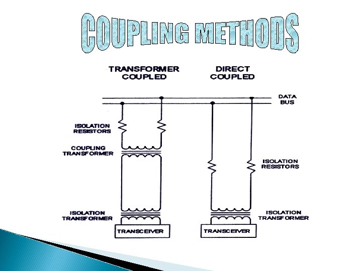
# It provides a medium for the exchange of data and information between various Avionics subsystems # Integration of Avionics subsystems in military or civil aircraft and spacecraft.

set of formal rules and conventions governing the flow of information among the systems Low level protocols define the electrical and physical standards High level protocols deal with the data formatting, including the syntax of messages and its format
 CSMA/CA")
Command/Response : Centralized Control Method Token Passing : Decentralized Control Method (Free token) CSMA/CA : Random Access Method

How the systems are interconnected in a particular fashion LINEAR NETWORK Linear Cable All the systems are connected in across the Cable RING NETWORK Point to Point interconnection Datas flow through the next system from previous system SWITCHED NETWORK Similar to telephone network Provides communications paths between terminals


Developed at Wright Patterson Air Force Base in 1970 s Published First Version 1553 A in 1975 Introduced in service on F-15 Programme Published Second version 1553 B in 1978

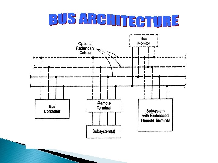
MIL-STD-1553, Command / Response Aircraft Internal Time Division Multiplex Data Bus, is a Military standard (presently in revision B), which has become one of the basic tools being used today for integration of Avionics subsystems
 Data")
Data Rate Word Length 1 Mbps 20 Bits Message Length 32 Word Strings(maximum) Data Bits per Word 16 Bits Transmission Technique Half - Duplex Encoding Manchester II Bi-phase Protocol Transmission Mode Command Response Voltage Mode
 REMOTE TERMINAL (RT) MONITORING TERMINAL (MT) TRANSMISSION MEDIA")
BUS CONTROLLER (BC) REMOTE TERMINAL (RT) MONITORING TERMINAL (MT) TRANSMISSION MEDIA


Single point failure in 1553 B leads to certificability problem in civil aircraft Addition of remote terminal requires changes in BC software which requires frequent certification Standard adopted in the year 1977 Made its appearance in the C-17 transport aircraft Point to Point Protocol

It is a specification that defines a local area network for transfer of digital data between avionics system elements in civil aircraft. It is simplex data bus using one transmitter but no more than twenty receivers for each bus implementation There are no physical addressing. But the data are sent with proper identifier or label Contd…

ARINC 429 is viewed as a permanent as a broadcast or multicast operation Two alternative data rates of 100 kbps and 12 -14 Kbps There is no bus control in the data buses as found in MIL-STD 1553 B It has direct coupling of transmitter and receiving terminals

ARINC 429 TRANSMITTER ARINC 429 DATABUS ARINC 429 RECEIVER UPTO 20 RECEIVERS TOTAL ARINC 429 RECEIVER


1977 => Boeing began to work on “DATAC” project 1977 - 85 => DATAC Emerged as ARINC 629 1989 => ARINC 629 was adopted by AEEC 1990 => ARINC 629 was first implemented in BOEING-777

Time Division Multiplex Linear Bus Multiple Transmitter Access 2 Mbps Data Rate Current Mode Coupling (Present implementation)
 Data")
Data Rate 2 Mbps Word Length 20 Bits Message Length 31 Word Strings(maximum) Data Bits per Word 16 Bits Transmission Technique Half - Duplex Encoding Manchester II Bi-phase Protocol Carrier Sense Multiple Access Collision avoidance Transmission Mode Voltage Mode, Current Mode, Fiber Optic Mode

ARINC 629 DATABUS ARINC 629 TERMINAL UPTO 120 SUBSCRIBER TERMINALS ARINC 629 TERMINAL

UNIT - IV

Head Up Display
 HUD uses high brightness CRT HUD projects some of the information")
Head-up Display (HUD) HUD uses high brightness CRT HUD projects some of the information normally on the primary flight displays and selected systems or weapons data into the LOS of the pilot without substantially dimming or obscuring the outer view HUD allows the pilot to simultaneously see critical aircraft information while viewing the outside scene

HUD…continued Every HUD contains, as a minimum In current HUD, ◦ Display generator ◦ Combiner ◦ Display Generator – CRT with P 43 (Green) phosphor ◦ Combiner – mirror with several unusual properties: Reflective coating – Highly wavelength selective in angle of incidence so that only that light which impinging within a very narrow range of angles will be reflected Combiner is sometimes incorrectly referred to as Hologram, but it contains no image information as found in true hologram

HUD…continued High performance aircraft HUDs use one of two basic designs for the combiner ◦ Single element combiner HUD ◦ Three element combiner HUD

Single element combiner HUD

Single element combiner HUD Simplest design of the two methods Transmission of outside scene is higher Less advantageous combiner HUD than three-element Transport aircraft uses this method

Three element combiner HUD

Three element combiner HUD Used on high-performance aircraft to achieve better producibility This design has achieved 30 o horizontal and 20 o vertical field of view All three elements contains gelatinous combiners as the middle layer, but only the forward element is curved to collimate the image from the CRT

HUD…continued HUD is brightness for maximum brightness Color HUDs are controversial for two reasons: ◦ There may be some loss of brightness, although brightness is becoming less of an issue as color CRTS improve ◦ Colors may be confused with or lost in the natural exterior scene Only extensive flight testing and field experience will ultimately resolve these questions Practical problem : HUD occupies large volume and the necessity to be mounted in the cockpit with the combiner in LOS to the pilot

HUD…continued On high performance aircraft, HUD is mounted at the top of and behind the instrument panel So that the combiner is between the top of the panel and the canopy in the pilot’s LOS when looking straight ahead For civil transport, HUD is mounted above the seat of each cockpit crew member, and the combiner is hinged to swing down into the LOS when HUD is in use, generally only during approach and landing Single element combiner can be used as an alternative for civil transport

A typical HUD

Typical Commercial Transport HUD

HUD in Cockpit

Head Level Display
 HLDs are another option for cockpit displays HLD avoids physiological")
Head Level Display (HLD) HLDs are another option for cockpit displays HLD avoids physiological limitation on eye refocusing time (as high as 200 ms) by placing directly below the HUD or top edge of the instrument panel display in which an image and supplement alphanumeric information are focused at a long distance, say about 50 m Thus the need for the pilot to refocus his eyes to scan at least some information inside the cockpit is eliminated

HLD…continued Normally HLD is used to display Radar or IR images or digital map HLD uses high intensity lamp coupled with dichronic filters to sort the white light into red, green and blue

Helmet Mounted Display
 HMD ◦ ◦ ◦ High brightness Excellent Resolution Lightweight Small")
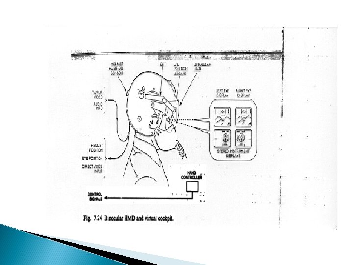
Helmet Mounted Display (HMD) HMD ◦ ◦ ◦ High brightness Excellent Resolution Lightweight Small size Monochrome HMD is advantageous over HUD Critical aircraft & stores information in in pilot’s LOS at all times, not just when he is looking straight ahead

HMD…continued HMD display format are similar to HUD format Design of HMD, factors to be considered are ◦ Weight: Helmets are designed using light weight materials ◦ Helmet Aerodynamics: Helmets are not designed for aerodynamics because during ejection, if designed for aerodynamics then it pulls the pilot’s neck upwards HMD is also used by Maintenance Personnel to have hands free and eyes fixed on the repair task at hand simultaneously viewing maintenance drawings and procedures

Figure showing HMD

Typical HMD for Fighter Aircraft

Night Vision Goggles
 Night-vision goggles are electronic widgets that allow you to see")
Night Vision Goggles (NVG) Night-vision goggles are electronic widgets that allow you to see things at night when it is too dark to see things with just your eyes alone Two type of Night Vision Imaging System (NVIS) ◦ Type I Uses only Binocular goggle with phosphor screen image Used generally in rotorcraft ◦ Type II Have same goggle as Type I, but provision has been made to allow the pilot to directly view the instruments through a combiner positioned below the goggle Commonly used in fixed wing aircraft

NVG… continued Because of enhanced sensitivity of NVIS to red and near IR, there are restrictions on the type of cockpit lighting that can be safely used to avoid washing out the outside scene Rotorcraft cockpit is limited to Blue, Green & Yellow and no Orange or Red is allowed Fixed wing aircraft can use full range of cockpit lighting provided that Red light originating in the cockpit does not have wavelength > 625 nm where the NVIS filter begins transmitting

Working Principle of NVG

New low cost NVG

High Resolution NVG

Military NVG

Surveillance photo taken without NVG

Surveillance photo taken using NVG

FAR 25. 1303 Federal aviation regulation dictate certain design constraints for the civil aircraft cockpits FAR 25. 1303 Flight and Navigation instruments requires each pilot station to be equipped eeith an airspped indicator, an altimeter, a rate of climb indicator, a gyroscopic rate –of-turn indicatorand pitch indicator. Additionally, instruments visible from each pilot station must include a free air temperature indicator , aclock, and a magnetic compass direction indicator
 (2) (3) (4) FAR 25. 1321 instruments: Installation, Arrangement and visibility")
T Configuration (1) (2) (3) (4) FAR 25. 1321 instruments: Installation, Arrangement and visibility prescribes the arrangement of the most important of these instruments in to familiar T. Paragraph. The instrument that most effectively indicates the attitude must be on the panel in the top center position The instrument that most effectively indicates airspeed must be adjacent to and directly left of the instrument in the top center position The instrument that most effectively indicates altitude must be adjacent to and directly right of the instrument in the top center position The instrument that most effectively indicates the direction of the flight must be adjacent to and directly below the instrument in the top center position

FAR 25. 1322 Instruments: Installation, Warning, Caution and Advisory lights This document requires the folowing colour code for indicator lights RED – for warning lights indicating a hazard that may require immediate corrective action AMBER - for caution lights indicating a condition that may require corrective action GREEN – This colour is to indicate safety operation

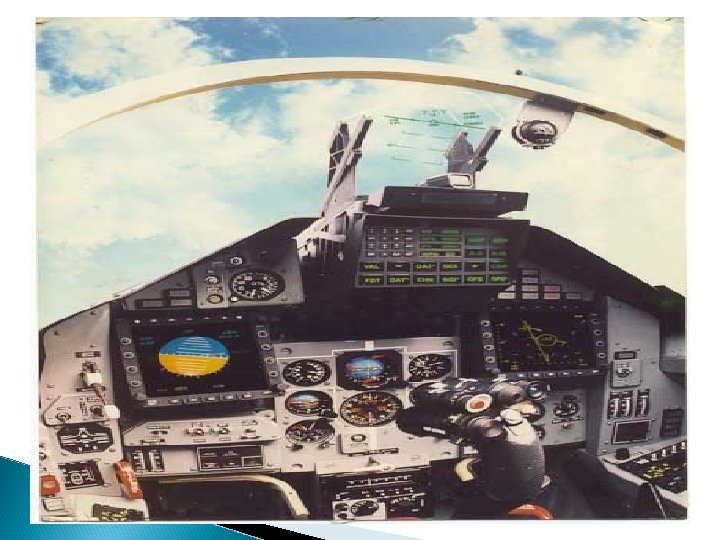
Boeing – 757 Cockpit The primary flight displays and the system uses colour CRT’s Display formats can be selected by the crew from a menu of possible options. When all the systems are normal, the cockpit is quiet and dark. Lights are illuminated or the aural warning are given only when the action is required for the crew Preflight checkout is accomplished by pushing each lighted switch in the overhead panel. The correct preflight sequence of of switch operation is ensured by going down each column of switches and folloeing a left to right pattern of column scan. When all the lighted switches are turned off preflight checkout has been successfully completed

Voice Interactive System It’s a kind of Interface between the crew and a/c in high work load situation in single crew member a/c F-16 routinely achieved 95% correct word recognition and reduced to less than 80% under high g conditions Voice control is not suitable for time critical system.

Categories Recognition ◦ Speech recognition Synthesis ◦ Mature and proven performer

Categories Recognition ◦ Speech recognition Synthesis ◦ Mature and proven performer

Voice Interactive System It’s a kind of Interface between the crew and a/c in high work load situation in single crew member a/c F-16 routinely achieved 95% correct word recognition and reduced to less than 80% under high g conditions Voice control is not suitable for time critical system.

Categories Recognition ◦ Speech recognition Synthesis ◦ Mature and proven performer

Speech recognition Applied for non critical task such as requesting system ◦ Status, ◦ tuning radios, ◦ And requesting maps to be displayed on a CRT Not been used for urgent Inputs or critical task such as firing weapons.

Problem with Voice Recognition The words in the vocabulary are limited. Generating templates are time consuming. Microphone have the same electrical characteristics as the flight microphone Difficult to stimulate the stress artificially Speaker independent Speech Recognition requires large amount of memory , and sow signal processing

Three possible responses by the system Correct recognition ◦ At a rate in the mid 90 % and decreases to less than 80% for a 9 -g load on the pilot Confusion with a rhyming word And rejection The response time and the recognition problems can be reduced by ◦ Syntactical rues and logic
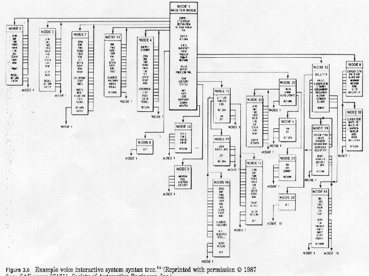

For the fig Node 1 is the master node ◦ Contains all the word that are permitted to § be the first word in a spoken sequence Node 2 to 4 are secondary nodes contains second words on the set of words based on the initial word and the syntactical rules. § Ex: Comm 1 refers radio , so logic dictate that the words which follow are numbers representing the frequency to which the radio should be tuned

UNIT - V

DIGITAL FLY BY WIRE

COMPARISON WITH MECHANICAL SYSTEM

MECHANICAL SYSTEM Variations in aerodynamic derivatives across flight envelope are compensated by auto-stabilisation gearing. Problems arise at the corners of flight envelope Lags in aircraft response to the steering commands from the autopilot affect the stability and limit the loop gain to be used.

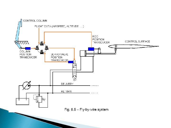
FLY BY WIRE FCS
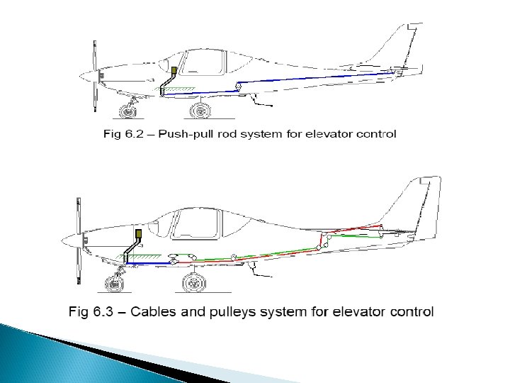

Mechanical Actuator

AIRCRAFT’S MOTION SENSOR Rate gyroscopes : Rate of rotation about roll, pitch and yaw axes. Linear accelerometers : Normal and Lateral acceleration. Air data sensors : Height and Airspeed. Airstream sensors : Incidence angles in longitudinal and lateral planes.

ESSENTIAL FEATURES Electrical Signal Transmission ◦ Pilot’s stick sensor signals, aircraft motion sensor signals , control surface actuator position signals and commanded control surface angles are transmitted electrically. Motion Sensor Feedback ◦ Failure survival, Redundant configuration of motion sensors.
 High Integrity, failure survival computing system ◦ Failure detection ◦")
ESSENTIAL FEATURES(Contd. , ) High Integrity, failure survival computing system ◦ Failure detection ◦ Fault isolation and system reconfiguration in the event of failure ◦ Computation of required control surface angles ◦ Monitoring ◦ Built in test. High Integrity, failure survival actuating system ◦ Electrical Feedback ◦ Time Lags are small.
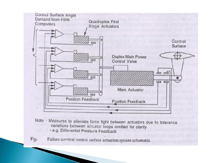
 Very High overall system integrity ◦ Probability of catastrophic failure")
ESSENTIAL FEATURES(Contd. , ) Very High overall system integrity ◦ Probability of catastrophic failure Civil <10 -9/hr. Military <10 -7/hr. FBW System is configured to be direct electrical implementation of mechanical system and thus has following advantages: ◦ ◦ ◦ Aircraft control system is transparent to the pilot Ability to limit power available to the pilot Integration of auto stabilisation system Ease of integration of autopilot Flexibility Lower weight and elimination of mechanical problems.

Elevon • 4 Nos. • Dual Hydraulics, • Quad. Electrical • DDV Control, • 9 Hz Frequency Response

INERTIAL NAVIGATION & GLOBAL POSITIONING SYSTEM

Inertial Navigation system It is a type of dead Reckoning system. It is the self contained , autonomous and unjammable. It measures linear motion and rotations using accelerometers and gyroscopes. From the initial navigation data obtained from the other navigation system or user, the navigation computer gives the attitude , position and velocity. It is faster than the data given by the GPS. INS is very accurate over the short distance. It is of two different configuration based on the Inertial sensor placement. They are a. Stable or Gimballed platform. b. Strap down platform

Stable or Gimballed Platform system: In which the Accelerometer and gyro are placed in the stable platform which is maintained stable by the gimbal system. Then the acceleration measured in the inertial coordinates Strap down Platform In this system the accelerometers are mounted on the vehicle platform and are therefore fixed to the vehicle coordinate system. The acceleration measured are then in vehicle coordinates Advantage and Disadvantage of Stable platform. It is very reliable, accurate and value for the money. The mechanical gimbal arrangement is very complex. Expensive and replacing , rebuild are very lengthy process Calibrations are very lengthy process

Geographic NED Frame

BODY FRAME

Axes transformation Transformation of a vector is given in one reference frame can be expressed with respect to another reference frame by the following methods: Ø Direction Cosine matrices Ø Euler angles Ø Quaternions method

DCM The transformation operator from one frame to another is called the direction cosine matrix (DCM)

Error in Ins System

Therefore Kalman filter correction applied to the INS as shown in the figure below,

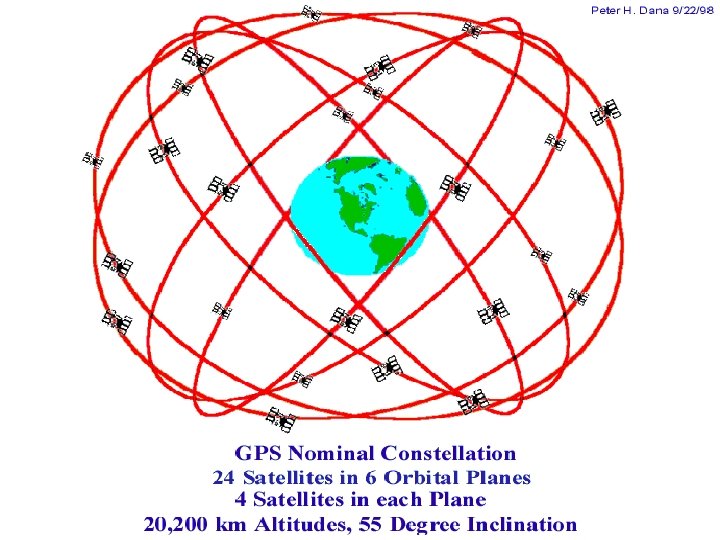
Why to go for satellite Navigation Satisfy as large a range of users as possible, military as well as civilian Relatively low user cost as well as ease-ofoperation Unrestricted access by all users Satisfy military positioning requirements

Initial Velocity Gravity Coralisis correction Static Conversion To NED frame Vn Ve Vup Height GUI Flight Simulator Inertial Sensor Conversion To attitude rates From file Conv. To 1553 B Body rates in body frame q, y, f Initial q, y, f Fig 4. Overall configuration of the INS simulator without error Correction


Positioning strategies Positioning by Ranging to Satellites

Biases and errors v. Biases Satellite dependent: ◦ Ephemeris uncertainties ◦ Satellite clock uncertainties ◦ Selective Availability effects Receiver dependent: ◦ Receiver clock uncertainties ◦ Reference station coordinate uncertainties Receiver-Satellite (or Observation) dependent: ◦ Ionospheric delay ◦ Tropospheric delay ◦ Carrier phase ambiguity

ERRORS ◦ ◦ Unmodelled, residual biases Carrier phase cycle slips Multipart disturbance Antenna phase centre offset ◦ Random observation error (noise)

MAINTAINABILITY AND RELIABILITY

Maintenance Measure of ability of an item to be retained in or restored to specified condition when maintenance is performed by personnel having specified skill levels, using prescribed procedures and resources, at each prescribed level of maintenance and repair

Maintenance Three questions about system maintenance- Who, When, Where ? ◦ Who will be doing the work ◦ When will it be done ◦ Where will it be done

Who will be doing the work? Skill level of maintenance personnel is a major consideration This necessitates a straight forward design which can be easily understood with BITE, procedures and associated displays Experience level of military personnel will be substantially less than those of their civil counterparts

When will it be done? Amount of time required for maintenance is one of the factor to be considered Reducing this time will yield an equal reduction in sortie turn around time Architecture should be designed to allow the aircraft to be dispatched with an inoperative unit and repaired during a scheduled maintenance

Where will it be done? Maintenance tasks may be performed in ◦ Flight line ◦ Maintenance depot Distribution of tasks should be established early in the design This distribution influences the design of BITEs and accessability to LRUs

Designing for easy maintenance Avionics designed for easy maintenance are major contributors for increasing the mission effectiveness while reducing operating costs Make maintenance manuals, procedures, and equipments easy to use and understand Use of standard units for design Accessibility of LRUs in both flight line and shop Each function should be implemented on a single replacable unit

Designing for easy maintenance -Contd ESD sensitive devices should have protection facilities built in to the LRUs No connectors should be on the front of the LRUs according to DOD-STD-1788 and ARINC 600 standard Testing a good unit is as expensive as testing a bad unit

BITE BITE – Built In Test Equipment A powerful maintenance tool that takes advantage of the intrinsic capabilities of digital avionics It should be capable of providing extensive data for engineering analysis It should be a part of the design to have maximum effectiveness Criticality and predicted failure rate of a unit drive its design

BITE - Contd It can be periodic, continuous or on demand depending on the criticality of the unit Uses a building block approach, testing from lowest-level function to the highest BITE should be able to recongnize and correctly identify at least 95% of possible faults Failure of BITE should also be clearly indicated

BITE TESTS ARINC Report 604 Guidance for Design and use of Built-in-Test Equipment ◦ ◦ LRU power-up self test In-flight fault Recording LRU replacement verification test System performance test

Reliability The duration or probability of failure-free performance under stated conditions The probability that an item can perform its intended functions for a specified interval under stated conditions

Reliability Analysis Well known method is to use failure prediction methods n Equip = Ni Gi Qi i-1 Where = total equipment failure rate Equip Gi = generic failure rate for the generic part type = quality factor for ith generic part type Qi Ni = quantity of ith generic part type n = number of different generic part types

THANK YOU
b1ad69ba85dfb0a4c84739749ddc48f5.ppt