530cc2448afb1d728e5024ba93834b2b.ppt
- Количество слайдов: 121


Advanced telecommunications for wireless systems Investigating OFDM by Math. CAD Timo Korhonen, Communications Laboratory, TKK

Motto • If you tell me – I forget • If you show me – I will remember • If you involve me – I can understand - a Chinese proverb

Topics • The objective of workshop OFDM module is to get familiar with OFDM physical level by using Math. CAD for system studies. • Topics: – – – – – OFDM Signal in time and frequency domain Channel model and associated effects to OFDM Windowing Cyclic prefix Peak-to-average power ratio (PAPR) OFDM transceiver Water-pouring principle System modeling: Constellation diagram, error rate System impairments

References for exercises • http: //site. ebrary. com/lib/otaniemi – Bahai, Ahmad R. S: Multi-Carrier Digital Communications : Theory and Applications of OFDM – Hara, Shinsuke: Multicarrier Techniques for 4 G Mobile Communications – Prasad, Ramjee: OFDM for Wireless Communications Systems – Xiong, Fuqin: Digital Modulation Techniques. Norwood, MA, USA • www. wikipedia. com

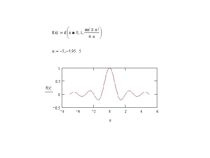
Exercise: Using Math. CAD • Plot the sinc-function • Create a script to create and draw a rectangle waveform. • Demonstrate usage of FFT by drawing a sinwave and its spectra. • Determine Fourier-series coefficients of a sinusoidal wave and plot the wave using these coefficients • Prepare a list of problems/solutions encountered in your tasks.

Rect waveform. mcd

Spectra of a sinus wave. mcd

Fourier transformation of a sinusoidal wave. mcd

Introduction

Background • Objectives: High capacity and variable bit rate information transmission with high bandwidth efficiency • Limitations of radio environment, also Impulse / narrow band noise • Traditional single carrier mobile communication systems do not perform well if delay spread is large. (Channel coding and adaptive equalization can be still improve system performance)

OFDM • Each sub-carrier is modulated at a very low symbol rate, making the symbols much longer than the channel impulse response. • Discrete Fourier transform (DFT) applied for multi-carrier modulation. • The DFT exhibits the desired orthogonality and can be implemented efficiently through the fast fourier transform (FFT) algorithm.

Basic principles • The orthogonality of the carriers means that each carrier has an integer number of cycles over a symbol period. • Reception by integrate-and-dump-receiver • Compact spectral utilization (with a high number of carriers spectra approaches rectangularshape) • OFDM systems are attractive for the way they handle ISI and ICI, which is usually introduced by frequency selective multipath fading in a wireless environment. (ICI in FDM)

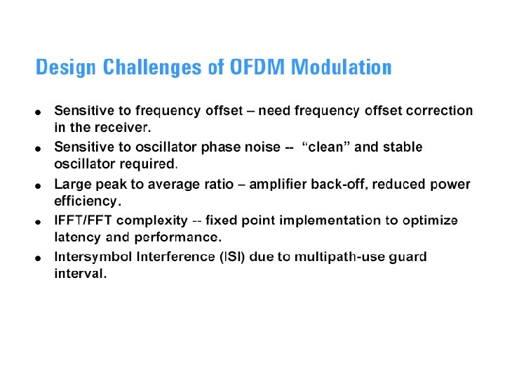
Drawbacks of OFDM • The large dynamic range of the signal, also known as the peak-to-average-power ratio (PAPR). • Sensitivity to phase noise, timing and frequency offsets (reception) • Efficiency gains reduced by guard interval. Can be compensated by multiuser receiver techniques (increased receiver complexity)
 in the following systems: • •")
Examples of OFDM-systems OFDM is used (among others) in the following systems: • • • IEEE 802. 11 a&g (WLAN) systems IEEE 802. 16 a (Wi. MAX) systems ADSL (DMT = Discrete Multi. Tone) systems DAB (Digital Audio Broadcasting) DVB-T (Digital Video Broadcasting) OFDM is spectral efficient, but not power efficient (due to linearity requirements of power amplifier= the PAPR-problem). OFDM is primarily a modulation method; OFDMA is the corresponding multiple access scheme.

OFDM Signal

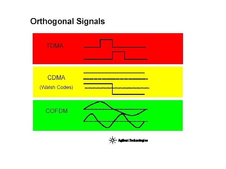
Multiplexing techniques
")
OFDM signal in time domain OFDM TX signal = Sequence of OFDM symbols gk(t) consisting of serially converted complex data symbols The k: th OFDM symbol (in complex LPE form) is where N = number of subcarriers, TG + TS = symbol period with the guard interval, and an, k is the complex data symbol modulating the n: th subcarrier during the k: th symbol period. In summary, the OFDM TX signal is serially converted IFFT of complex data symbols an, k

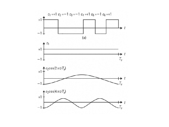
Orthogonality of subcarriers Definition: Orthogonality over the FFT interval: Phase shift in any subcarrier - orthogonality over the FFT interval should still be retained:
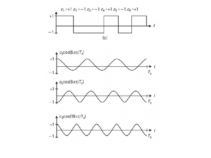

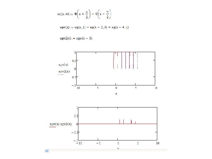
Exercise: Orthogonality • Create a Math. CAD script to investigate orthogonality of two square waves – #1 Create the rect-function – #2 Create a square wave using #1 – #3 Create a square wave with a time offset – #4 Add the waves and integrate

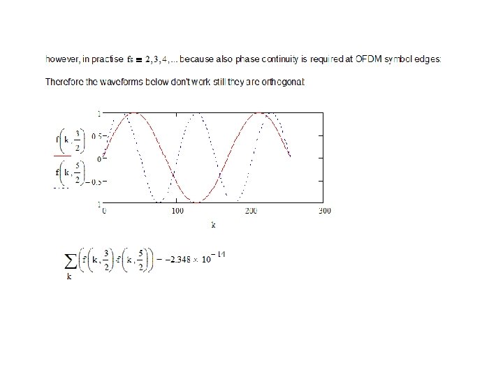
Exercise: Orthogonality of OFDM signals • Create and plot an OFDM signal in time domain and investigate when your subcarriers are orthogonal – #1 Create a function to generate OFDM symbol with multiple subcarriers – #2 Create a function to plot comparison of two subcarriers orthogonality (parameter is the frequency difference between carriers) • Note: also phase continuity required in OFDM symbol boarders – #3 Inspect the condition for orthogonality and phase continuity

Orthogonality. mcd

OFDM Spectra

OFDM in frequency domain TG TFFT Square-windowed sinusoid in time domain => "sinc" shaped subchannel spectrum in frequency domain See also A. 13 in Xiong, Fuqin. Digital Modulation Techniques. Norwood, MA, USA: Artech House, Incorporated, 2006. p 916. http: //site. ebrary. com/lib/otaniemi/Doc? id=1 0160973&ppg=932

Spectra for multiple carrier Single subchannel OFDM spectrum Subcarrier spacing = 1/TFFT Spectral nulls at other subcarrier frequencies

Next carrier goes here! http: //www. eng. usf. edu/wcsp/OFDM_links. html
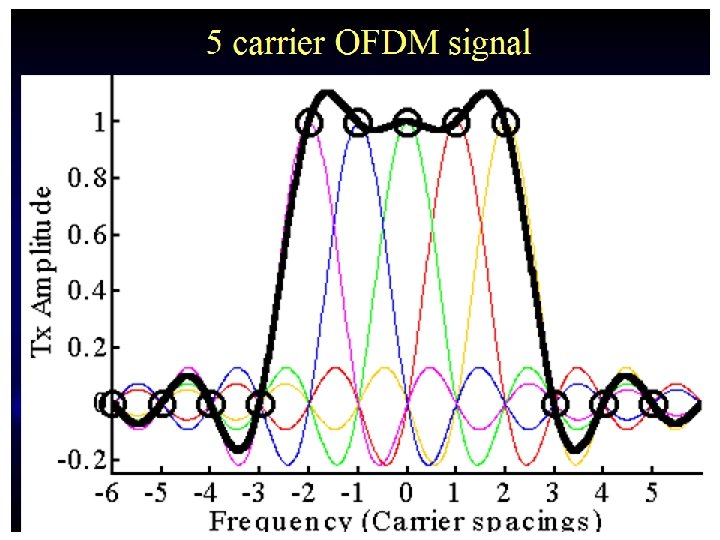

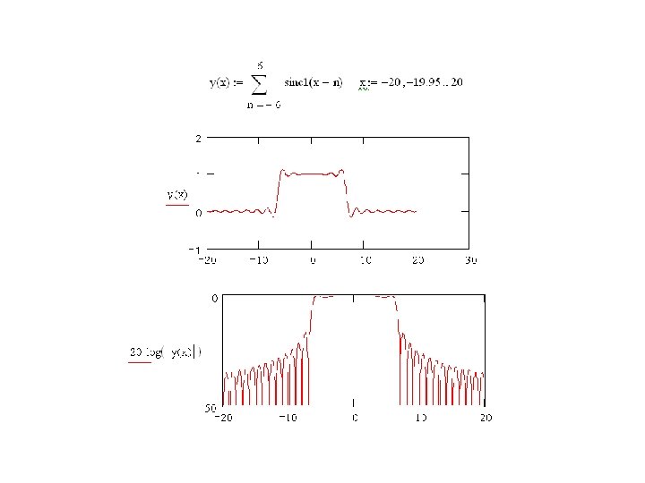
Exercise: Analytical spectra • Draw the spectra of OFDM signal by starting its frequency domain presentation (the sinc-function). Plot the spectra also in log-scale – #1 Plot three delayed sinc(x) functions in the range x = -1… 2 such that you can note they phase align correctly to describe the OFDM spectra – #2 Plot in the range from f = -20 to 20 Hz an OFDM spectra consisting of 13 carriers around f=0 in linear and log-scale

Ofdm spectra. mcd

Exercise: Spectra modified • Investigate a single OFDM carrier burst and its spectra by using the following script: – How the spectra is changed if the • Carrier frequency is higher • Symbol length is altered

OFDM Spectra by Math. CAD for a single carrier ofdm spectra by rect windowed sinc. mcd

Spectral shaping by windowing

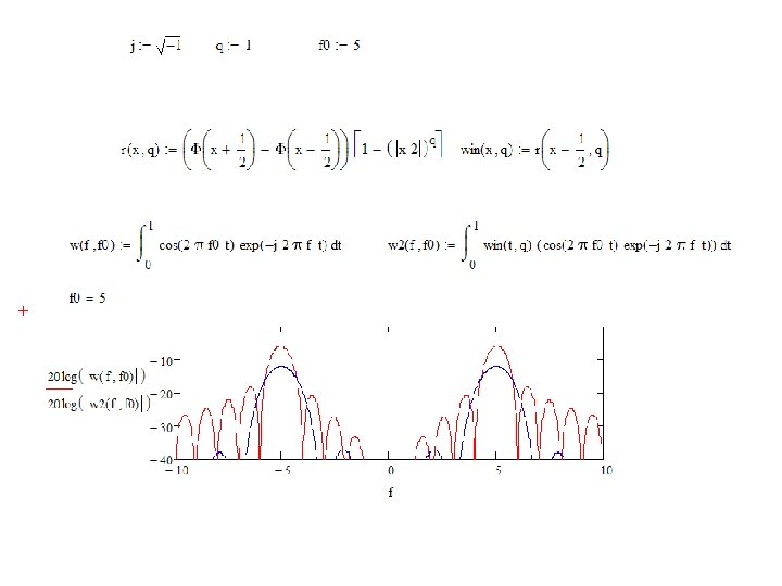
Exercise: Windowed spectra • The next Math. CAD script demonstrates effect of windowing in a single carrier. – How the steepness of the windowing is adjusted? – Why function win(x, q) is delayed by ½? – Comment the script

burst windowing and ofdm spectra. mcd

Modeling OFDM Transmission
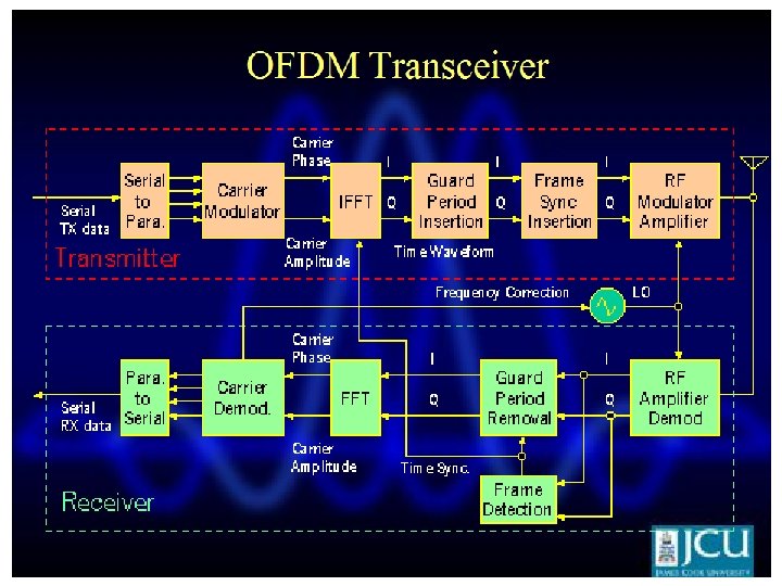

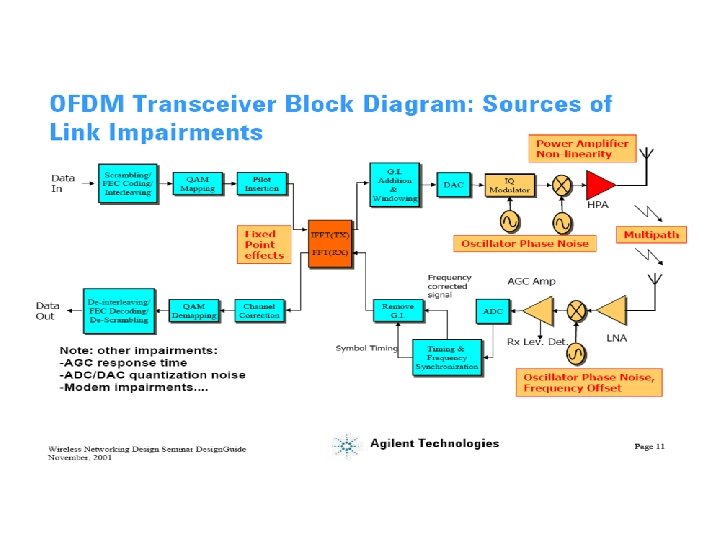
Transceiver • Some processing is done on the source data, such as coding for correcting errors, interleaving and mapping of bits onto symbols. An example of mapping used is multilevel QAM. • The symbols are modulated onto orthogonal sub -carriers. This is done by using IFFT • Orthogonality is maintained during channel transmission. This is achieved by adding a cyclic prefix to the OFDM frame to be sent. The cyclic prefix consists of the L last samples of the frame, which are copied and placed in the beginning of the frame. It must be longer than the channel impulse response.
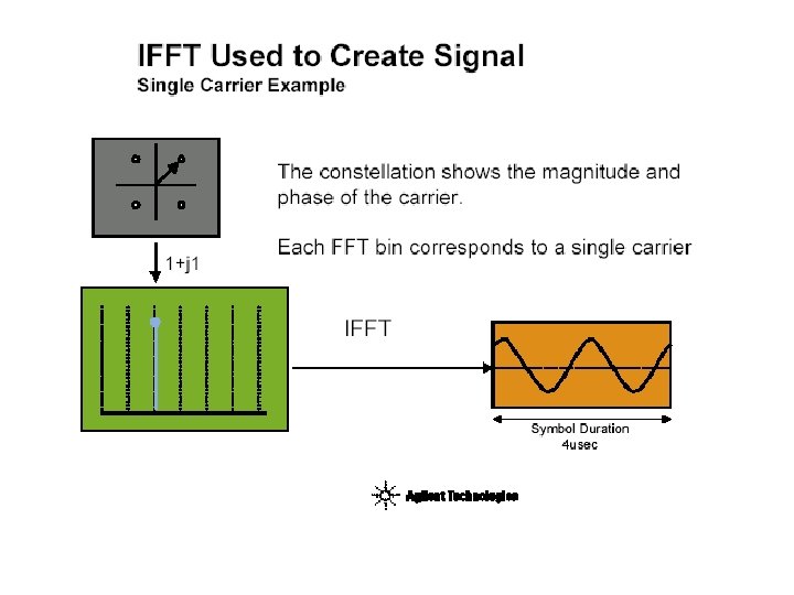
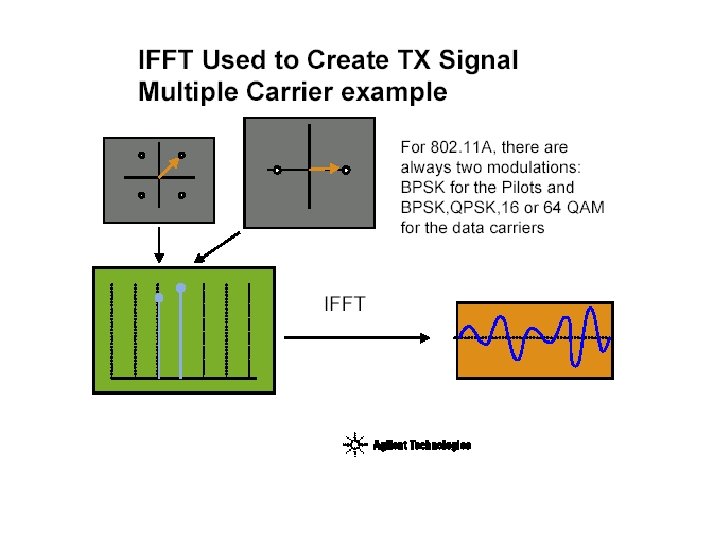

OFDM and FFT http: //www. eng. usf. edu/wcsp/OFDM_links. html ~ Aalborg-34 -lecture 13. pdf

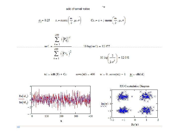
Exercise: Constellation diagram of OFDM system • Steps – #1 create a matrix with complex 4 -level QAM constellation points – #2 create a random serial data stream by using outcome of #1. Plot them to a constellation diagram. – #3 create complex AWGN channel noise. Calculate the SNR in the receiver. – #4 form and plot the received complex noisy time domain waveform by IFFT (icfft-function) – #5 detect outcome of #4 by FFT and plot the resulting constellation diagram

Exercise : Constellation diagram of OFDM Ofdm system. mcd

Channel

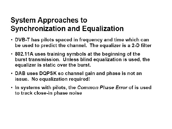
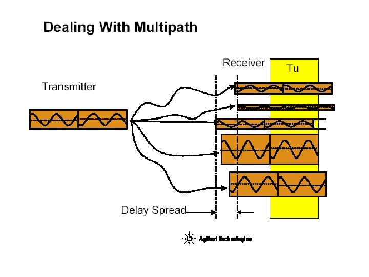
Combating multipath channel • Multipath prop. destroys orthogonality • Requires adaptive receiver – channel sensing required (channel sounding by pilot tones or using cyclic extension) • Remedies – Cyclic extension (decreases sensitivity) – Coding • One can deal also without cyclic extension (multiuser detection, equalizer techniques) – More sensitive receiver in general – More complex receiver - more power consumed

Pilot allocation example To be able to equalize the frequency response of a frequency selective channel, pilot subcarriers must be inserted at certain frequencies: Time Pilot subcarriers at some, selected frequencies Between pilot subcarriers, some form of interpolation is necessary! Subcarrier of an OFDM symbol Frequency

Pilot allocation example cont. - A set of pilot frequencies The Shannon sampling theorem must be satisfied, otherwise error-free interpolation is not possible: maximum delay spread Time Frequency

Channel • Path Loss • Shadow Fading • Multipath: – Flat fading – Doppler spread – Delay spread • Interference • OFDM: – Inter-symbol interference (ISI) – flat fading, sampling theorem must be fulfilled – Inter-carrier interference (ICI) – multipath propagation (guard interval)

Multipath radio channel

* *Spike distance depends on impulse response

Multipath channel model

Received signal Pr: Received mean power Gs: Shadow fading Log r ~ Fast fading

Exercise: Modeling channel • Create a Math. CAD script to create artificial impulse and frequency response of a multipath channel (fast fading) – #1 Create an array of complex AWGN – #2 Filter output of #1 by exp(-5 k/M) where M is the number of data points – #3 Plot the time domain magnitude of #2 • Is this a Rayleigh or Rice fading channel? • How to make it the other one than Rayleigh/ Rice – #4 Plot #3 in frequency domain

Comment how realistic this simulation is? Rayleigh or Rice fading channel? impulse response radio ch. mcd

Frequency response shown by swapping left-hand side of the fft

Exercise: Rayleigh distribution • #1 create a Rayleigh distributed set of random numbers (envelope of complex Gaussian rv. ) • #2 plot the pdf of #1 (use the histogramfunction) • #3 add theoretical pdf to #2

Rayleigh distribution - Note that true pdf area equals unity, how could you adjust the above for this? - Add comparison to theoretical Rayleigh distribution!

Path loss
: Log normal distribution")
Shadow fading N(0, s 2): Log normal distribution

Doppler spread

DELAY SPREAD IN TIME DOMAIN Small delay spread Large delay spread

Delay spread in frequency domain

Exercise: Variable channel • Discuss a model of a channel with flat/ frequency selective characteristics and report its effect to the received modulated wave – Amplitude and phase spectra – What happens to the received frequency components in • • Flat fading Frequency selective fading Time invariant / time variant channel Doppler effected channel

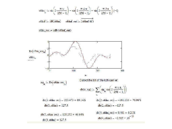
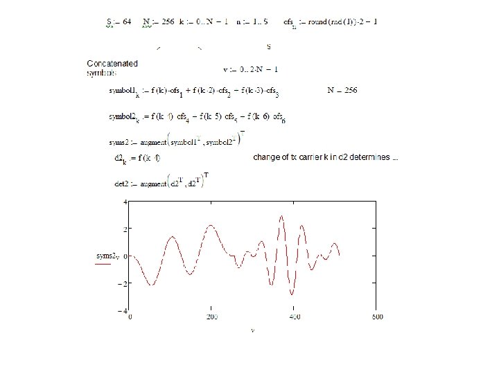
Exercise: ODFM in a multipath channel • #1 Create an impulse response of 256 samples with nonzero values at h 2=16, h 10=4+9 j, and h 25= 10+3 j and plot its magnitude spectra • #2 Create OFDM symbol for three subcarriers with 1, 2 and 3 cycles carrying bits 1, -1 and 1 • #3 Launch the signal of #2 to the channel of #1 and plot the OFDM signal before and after the channel to same picture. • #4 Detect (Integrate an dump) the bits after and before the channel and compare. See the generated ICI also by detecting the 4: n ‘carrier’!

The channel OFDM in a multipath channel. mcd

Single carrier transmission and rms delay spread Determine by using Math. CAD’s linterp-function the maximum rate for delay spread of 70 us!

Rate and delay spread. mcd

Cyclic prefix
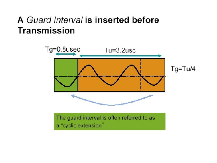

Example: a two-path channel

Home exercise: Orthogonality and multipath channel • Demonstrate by Math. CAD that the orthogonality of OFDM signal can be maintained in a multipath channel when guard interval is applied – #1 modify syms 2 -signal to include a cyclic prefix – #2 introduce multipath delays not exceeding the duration of cyclic prefix (apply the rot-function) – #3 determine integrate and dump detected bits for #2 and especially for carriers that are not used to find that no signal is leaking into other subcarriers -> ICI is avoided!

cyclic prefix. mcd

Detection

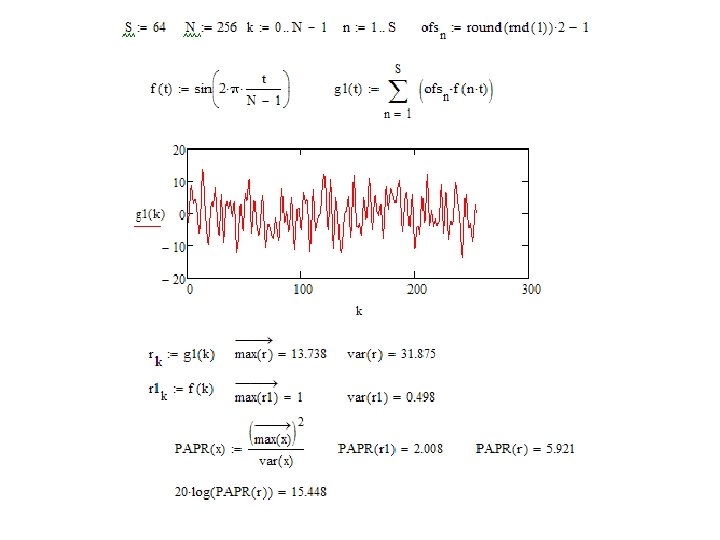
Peak-power problem

Envelope Power Statistics

Exercise • Create an OFDM signal in time domain and determine experimentally its PAPR • Experiment with different bit-patterns to show that the PAPR is a function of bit pattern of the symbol – #1 create 64 pcs BPSK LPE bits – #2 define a function to create OFDM symbol with the specified number of carriers (with 256 samples) carrying bits of #1 – #3 check that the carriers are generated correctly by a plot – #4 determine PAPR for a set of 64 OFDM subcarriers. Compare with different bit patterns (eg. evaluate #1 again by pressing F 9)

OFDM papr. mcd
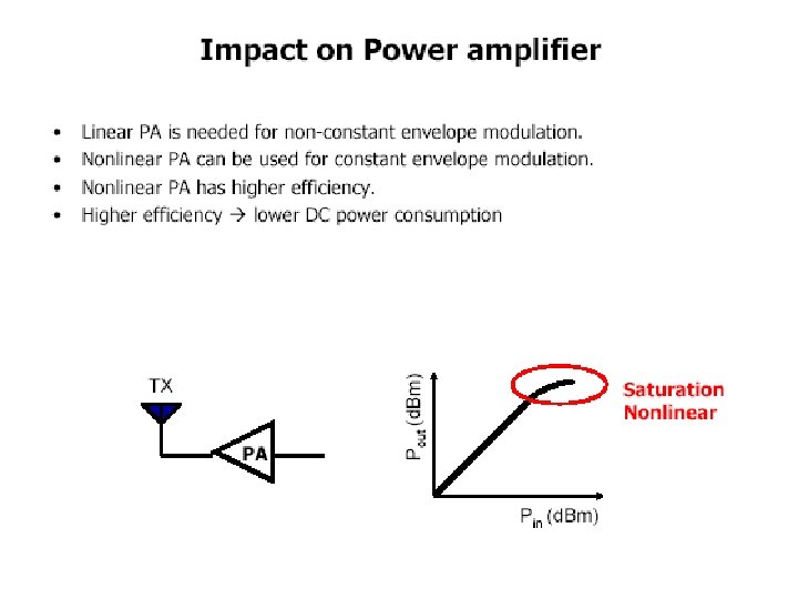

Transfer characteristics of power amplifier

Exercise: Non-linear distortion • Demonstrate build-up of harmonics for a sinusoidal wave due to non-linearity of a power amplifier – #1 Create a sinusoidal wave, 256 samples and 8 cycles – #2 Create a clipping function that cuts a defined section of wave’s amplitudes – #3 Apply #2 to #1 and plot the result – #4 compare #1 to #3 in frequency domain logscale with different levels of clipping
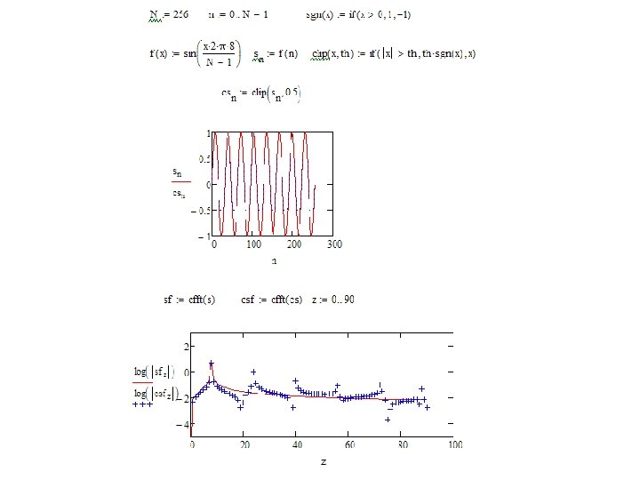
 – Cons: Table look-up required at the receiver")
PAPR suppression • Selective mapping (coding) – Cons: Table look-up required at the receiver • Signal distortion techniques – Clipping, peak windowing, peak cancellation – Cons: Symbols with a higher PAPR suffer a higher symbol error probability Prasad, Ramjee. OFDM for Wireless Communications Systems. Norwood, MA, USA: Artech House, Incorporated, 2004. p 150. http: //site. ebrary. com/lib/otaniemi/Doc? id=10081973&p pg=166

Selective mapping

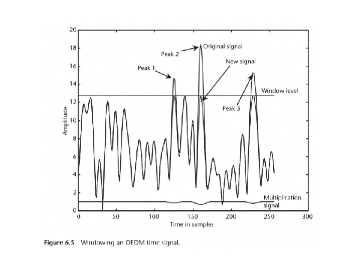
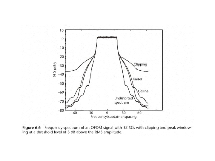
Clipping • Cancel the peaks by simply limiting the amplitude to a desired level – Self-interference – Out-of band radiation • Side effects be reduced by applying different clipping windows

Peak cancellation
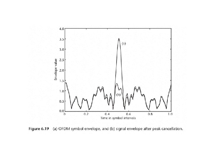
 undistorted b) peak cancellation c) clipping")
Comparing clipping and peak cancellation a) undistorted b) peak cancellation c) clipping
")
Effect of peak cancellation on packet error rate (PER)

OFDM transceiver

System error rate • In AWGN channel OFDM system performance same as for single-carrier • In fading multipath a better performance can be achieved – Adjusts to delay spread – Allocates justified number of bits/subcarrier

DESIGN EXAMPLE

Exercise: BPSK error rate
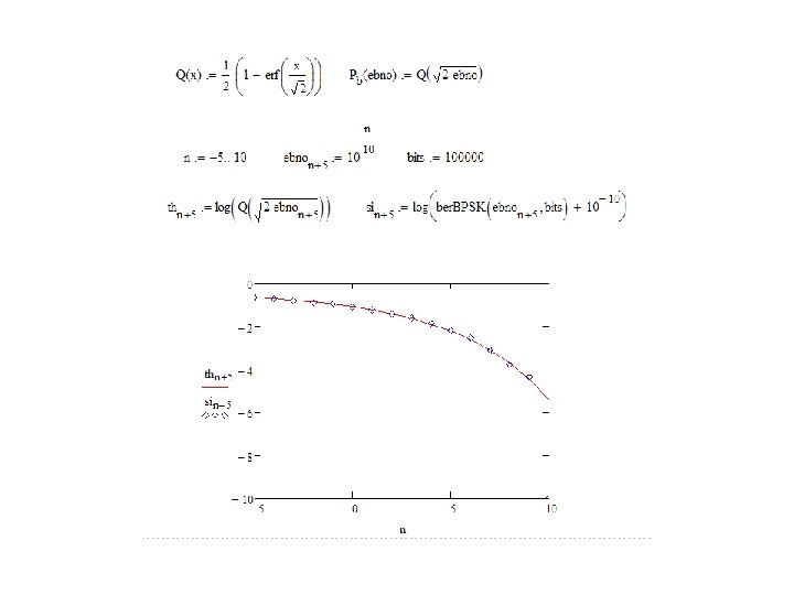

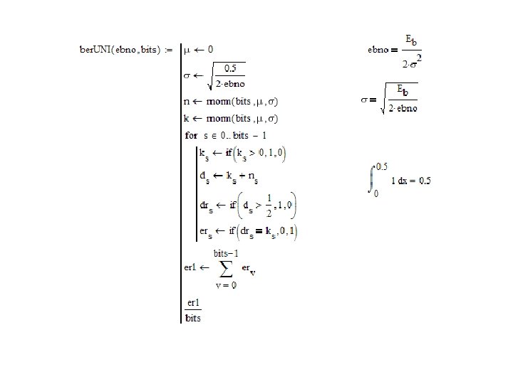
How would you modify this function to simulate unipolar system?
 to find out")
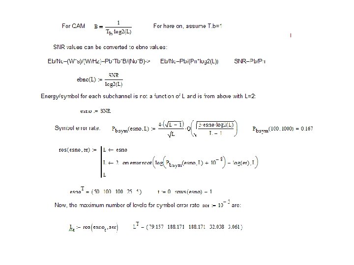
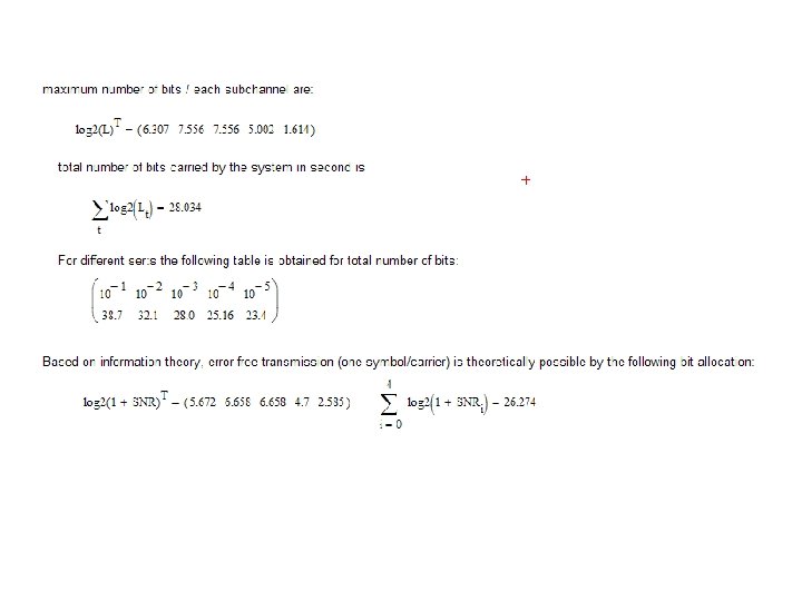
Bit allocation for carriers • Each carrier is sensed (channel estimation) to find out the respective subchannel SNR at the point of reception (or channel response) • Based on information theory, only a certain, maximum amount of data be allocated for a channel with the specified BT and SNR • OFDM bit allocation policies strive to determine optimum number of levels for each subcarrier to (i) maximize rate or (ii) minimize power for the specified error rate
, noise")
Water-pouring principle • Assume we know the received energy for each subchannel (symbol), noise power/Hz and the required BER • Assume that the required BER/subchannel is the same for each subchannel (applies when relatively high channel SNR) • Water-pouring principle strives to determine the applicable number of levels (or bit rate) for subcarriers to obtain the desired transmission


Home exercise 2: Water pouring principle • Follow the previous script and… – Explain how it works by own words – Comment the result with respect of information theory

System impairments

http: //www. eng. usf. edu/wcsp/OFDM_links. html

Exercise ICI • Create a Math. CAD script to investigate frequency offset produced ICI

Summary
530cc2448afb1d728e5024ba93834b2b.ppt