

d304cfc41cb7d9ffa5a1ca1c5aa18428.ppt
- Количество слайдов: 40
 Advanced Energy Systems and Heat and Mass Transfer Professor Nikola Stosic (CM 308, Ext 8925) Professor Ian K Smith (CM 308, Ext 8114) Dr Russel Lockett
 ADVANCED ENERGY SYSTEMS www. staff. city. ac. uk/~sj 376/energy. htm Low-Pollution Combustion Fuel and Combustion Boilers and Furnaces, Renewables Energy Management Calculation examples and problems Coursework
 Low-pollution Combustion: Fuels and Combustion General on fuels and combustion Theoretic relations, Excess of air, Combustion products Callorific value, H-t Diagram, Combustion temperatures Monitoring of combustion Fuel reserves, Environmental impacts
 Low Pollution Combustion Boilers and Furnaces General on furnaces and boilers, Boiler types, balance, Coefficient of utilization Heat-Temperature chart Monitoring of boiler processes, Radiation in furnaces, chambers and channels, Combined heat transfer ‘Zero emission’ combustion Fuel cells
 Energy Management Plant lifetime costs Fuel switching Storage Systems, thermal and mechanical Building management Industrial refrigeration
 Low-pollution Combustion: Fuels and Combustion General on fuels and combustion Solid fuel, coal, brown coal Liquid fuel, oil derivatives Gaseous fuel, natural gas
 Fuels and Combustion Example 1 Theoretic relations, Fuel components c - Carbon, h – Hydrogen, S – Sulphur o – Oxigen n – Nitrogen w – Water a - ashes c+h+s+n+o+w=1
 Fuels and Combustion Example 2 Theoretic relations, Air, Excess of air, Combustion products
 Fuels and Combustion Air, Excess of air
 Fuels and Combustion products
 Combustion Control, Measured are O 2 and CO 2
 Fuels and Combustion Ostwald triangle and Bunte diagram Example 6
 Combustion Products Specific Heat Example 3 Polynomial expression in function of temperature Cp = a + b. T + c. T 2 Mean specific heat Cp = a + 0. 5 b(T+To) + 0. 333 c(T 2+TTo+T 2 o) Mean specific heats for air, N 2, O 2, H 2 O, SO 2, CO, NO, OH, H 2 and CH 4
 Specific Heat: Table of Coefficients Comp AIR N 2 O 2 H 2 O SO 2 CO 2 a k. J/kmol. K 26. 719 27. 016 25. 593 29. 857 31. 163 27. 286 103 b k. J/kmol. K 2 106 c k. J/kmol. K 3 7. 372 -1. 1113 5. 811 -0. 2887 13. 251 -4. 205 11. 046 0. 192 33. 394 -10. 752 38. 469 -11. 262 M kg/kmol 28. 964 28. 01 32. 18. 02 64. 02 44. 05 CO NO OH H 2 CH 4 26. 568 26. 945 29. 754 29. 062 13. 405 7. 577 11. 255 -0. 881 -0. 82 77. 027 28. 01 30. 01 17. 01 2. 016 16. 04 -1. 119 -1. 76 1. 7547 1. 99 -18. 744
 Combustion Products Enthalpy H =SVi hi = TSVi cpi =T[V CO 2 cp. CO 2 +VH 2 O cp. H 2 O +V SO 2 cp. SO 2 + VN 2 cp N 2 +(l -1) VAir, m cp. Air ] k. J/kg where: V CO 2 = 1. 867 c; V H 2 O = 11. 2 h + 1. 244 w ; V SO 2=0. 7 s and VN 2 = 0. 8 n + 0. 79 VAir, m m 3 /kg H-t diagram, Example 4 gives relation between the temperature and enthalpy where excess of air is parameter. From it, either enthalpy, temperature or excess of air can be estimated graphically. Also these can be calculated, Example 5.
+10, 900 s-2500 w k. J/kg Hu=34, 000 c+142,") Calorific Value Hl=34, 000 c+120, 000(h-o/8)+10, 900 s-2500 w k. J/kg Hu=34, 000 c+142, 000(h-o/8)+10, 900 s k. J/kg
Calorific Value Hl=34, 000 c+120, 000(h-o/8)+10, 900 s-2500 w k. J/kg Hu=34, 000 c+142, 000(h-o/8)+10, 900 s k. J/kg
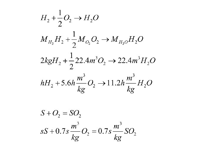
 Incomplete Combustion Complete combustion: C+O 2 ->CO 2 H 2+1/2 O 2 -> H 2 O S+O 2 ->SO 2 Incomplete combustion due to dissociation Formation Heat T 0=288 K Reaction DH 0 k. J/kmol ln. Kp 0 CO 2 <-> CO+1/2 O 2 283, 197 -103, 010 H 2 O<-> H 2+1/2 O 2 241, 710 -91, 870 H 2 O<-> OH+1/2 H 2 284, 030 -106, 510 NO <-> 1/2 N 2+1/2 O 2 90, 624 -34, 925
 Combustion Kinetics a. A+b. B->c. C+d. D, w=k. PCIi w 1=k 1 CAa. CBb w 2=k 2 CCc. CDd w 1/w 2= k 1 CAa. CBb /k 2 CCc. CDd=1 K= k 1/k 2= CCc. CDd/CAa. CBb Kp= p. Cc p. Dd/p. Aa p. Bb d(ln. Kp)/d. T=DH/RT 2 =[a. T+1/2 b. T 2+1/3 c. T 3+C 1] /RT 2 =[a/T+1/2 b. T+1/3 c. T 2+C 1/T] /R ln. Kp=a ln. T/R+b. T/2 R+c. T 2/6 R+C 1/RT+C 2 R is universal gas constant, 8314 J/kmol, C 1 and C 2 are constants determined for T 0 Example 7
 Combustion: Kinetic: Premixed fuel and air, slow chemical reaction determines the combustion speed Diffusive: Simultaneous mixing and chemical reaction, slow mixing determines the speed Combustion speed: 1/w=1/wm+1/wc Control combustion: distribution of air or fuel
 Steam Boilers Heat apparatus to produce steam or hot water Combustion chamber, furnace Water heater Evaporator Superheater Air preheater
 History: Early 1800 quality fuel, low efficiency low capacity and low steam pressure 1900 the same principles as today 1930 the same technology as today, Forging and welding Today, 2000 MW, 130 m high, big plant
 Associate topics in: Combustion: flow and chemical reaction Heat transfer: radiation and convection Fluid dynamics, turbulent flow Structure and strength of materials Process control: combustion, water feed, steam temperature
=Qhb=BHlhb B=D(hs -hs)/(Hlhb)") Mass and energy balance of a steam boiler Q=BHl Q 1=D(hs -hs)=Qhb=BHlhb B=D(hs -hs)/(Hlhb) hb= Q 1/Q Q - heat into boiler, k. W (MW) Q 1 - energy used in the boiler, k. W D - boiler production of steam, kg/s (t/h) B - consumption of fuel, kg/s Hl - fuel calorific value, k. J/kg hs - enthalpy of superheated steam, k. J/kg hs - enthalpy of feed water, k. J/kg hb – boiler efficiency
Mass and energy balance of a steam boiler Q=BHl Q 1=D(hs -hs)=Qhb=BHlhb B=D(hs -hs)/(Hlhb) hb= Q 1/Q Q - heat into boiler, k. W (MW) Q 1 - energy used in the boiler, k. W D - boiler production of steam, kg/s (t/h) B - consumption of fuel, kg/s Hl - fuel calorific value, k. J/kg hs - enthalpy of superheated steam, k. J/kg hs - enthalpy of feed water, k. J/kg hb – boiler efficiency
 Efficiency coefficient of a steam boiler hb= Q 1/Q=1 -Sui Q - heat into boiler, k. W (MW) Q 1 - energy used in the boiler, k. W Loses Gasification loses u 1 -u 3 because of unburned fuel u 1 - drop through grid u 2 - unburned in flying ashes u 3 - unburned in laying ashes Furnace loses u 1 -u 6 because combustion products did not receive heat u 4 - chemically unburned u 5 - heat lost through carbonization u 6 - heat lost with laying ashes Boiler loses u 1 -u 8 because water did not receive heat u 7 - loss with the combustion products u 8 - external cooling
 Qe=D(h” –h’)=B(HF 0 –HF 2), k.") Mass and energy balance of an evaporator (furnace) Qe=D(h” –h’)=B(HF 0 –HF 2), k. W Heat exchanged mainly by radiation Qe- heat exchanged in the evaporator, k. W HF 0 – theoretical enthalpy in the furnace, k. J/kg HF 2 – enthalpy of CP at the end of the furnace, k. J/kg h” - enthalpy of saturated steam at boiler pressure, k. J/kg h’ - enthalpy of water at boiler pressure, k. J/kg
Mass and energy balance of an evaporator (furnace) Qe=D(h” –h’)=B(HF 0 –HF 2), k. W Heat exchanged mainly by radiation Qe- heat exchanged in the evaporator, k. W HF 0 – theoretical enthalpy in the furnace, k. J/kg HF 2 – enthalpy of CP at the end of the furnace, k. J/kg h” - enthalpy of saturated steam at boiler pressure, k. J/kg h’ - enthalpy of water at boiler pressure, k. J/kg
 Heat Transfer in Furnaces Dominated by radiation Example 10
=B(HF 2 –Hg 1)=As ks Dtlog,") Mass and energy balance of a superheater Qs=D(hs-h” )=B(HF 2 –Hg 1)=As ks Dtlog, k. W 1/ks =1/h 1+ d/l +1/h 2 Dtlog=(Dth- Dtl)/ln Dth/ Dtl Heat exchanged mainly by convection Qs- heat exchanged in the superheater, k. W ks- heat transfer coefficient in the superheater, k. W/m 2 K h 1 - convection heat transfer coefficient for combustion products, k. W/m 2 K h 2 - convection heat transfer coefficient for steam, k. W/m 2 K l - conduction heat transfer for the pipe, k. W/m. K d– pipe and fouling thickness, m Dtlog, Dth, Dtl – logarithmic and higher and lower temperature differences
Mass and energy balance of a superheater Qs=D(hs-h” )=B(HF 2 –Hg 1)=As ks Dtlog, k. W 1/ks =1/h 1+ d/l +1/h 2 Dtlog=(Dth- Dtl)/ln Dth/ Dtl Heat exchanged mainly by convection Qs- heat exchanged in the superheater, k. W ks- heat transfer coefficient in the superheater, k. W/m 2 K h 1 - convection heat transfer coefficient for combustion products, k. W/m 2 K h 2 - convection heat transfer coefficient for steam, k. W/m 2 K l - conduction heat transfer for the pipe, k. W/m. K d– pipe and fouling thickness, m Dtlog, Dth, Dtl – logarithmic and higher and lower temperature differences
=B(Hg 1 –Hg 2)=Aa ka") Mass and energy balance of a water heater Qa=D(h’-ha )=B(Hg 1 –Hg 2)=Aa ka Dtlog, k. W 1/ka =1/h 1+ d/l +1/h 2 Heat exchanged mainly by convection Qa- heat exchanged in the water heater, k. W ka- heat transfer coefficient in the water heater, k. W/m 2 K h 1 - convection heat transfer coefficient for combustion products, k. W/m 2 K h 2 - convection heat transfer coefficient for steam, k. W/m 2 K l - conduction heat transfer for the pipe, k. W/m. K d– pipe and fouling thickness, m Dtlog– logarithmic temperature difference Q 1=D(hs -hs)= D(hs-h” )+D(h” –h’)+ D(h’-ha )
Mass and energy balance of a water heater Qa=D(h’-ha )=B(Hg 1 –Hg 2)=Aa ka Dtlog, k. W 1/ka =1/h 1+ d/l +1/h 2 Heat exchanged mainly by convection Qa- heat exchanged in the water heater, k. W ka- heat transfer coefficient in the water heater, k. W/m 2 K h 1 - convection heat transfer coefficient for combustion products, k. W/m 2 K h 2 - convection heat transfer coefficient for steam, k. W/m 2 K l - conduction heat transfer for the pipe, k. W/m. K d– pipe and fouling thickness, m Dtlog– logarithmic temperature difference Q 1=D(hs -hs)= D(hs-h” )+D(h” –h’)+ D(h’-ha )
=B(Hg 1 –Hg 2)=Az kz") Mass and energy balance of an air preheater Qz=B(HL-Hl )=B(Hg 1 –Hg 2)=Az kz Dtlog, k. W 1/kz =1/h 1+ d/l +1/h 2 Heat exchanged mainly by convection Qz- heat exchanged in the air preheater, k. W kz- heat transfer coefficient in the air preheater, k. W/m 2 K h 1 - convection heat transfer coefficient for combustion products, k. W/m 2 K h 2 - convection heat transfer coefficient for steam, k. W/m 2 K l - conduction heat transfer for the pipe, k. W/m. K d– pipe and fouling thickness, m Dtlog– logarithmic temperature difference
Mass and energy balance of an air preheater Qz=B(HL-Hl )=B(Hg 1 –Hg 2)=Az kz Dtlog, k. W 1/kz =1/h 1+ d/l +1/h 2 Heat exchanged mainly by convection Qz- heat exchanged in the air preheater, k. W kz- heat transfer coefficient in the air preheater, k. W/m 2 K h 1 - convection heat transfer coefficient for combustion products, k. W/m 2 K h 2 - convection heat transfer coefficient for steam, k. W/m 2 K l - conduction heat transfer for the pipe, k. W/m. K d– pipe and fouling thickness, m Dtlog– logarithmic temperature difference
 Diagram Gives a graphical presentation of heat transfer in a steam boiler") Q-t (Lentz) Diagram Gives a graphical presentation of heat transfer in a steam boiler Abscissa: Temperature Ordinate: Heat transferred A ka=Q/Dt Area in the Q: 1/ Dt diagram represents a measure of a heat transfer efficiency Example 8
Q-t (Lentz) Diagram Gives a graphical presentation of heat transfer in a steam boiler Abscissa: Temperature Ordinate: Heat transferred A ka=Q/Dt Area in the Q: 1/ Dt diagram represents a measure of a heat transfer efficiency Example 8
 Low-Polluting Combustion Particles, CO, SO 2, Cm. Hn, NOx Staged Combustion Fluidized Bed Gasification Fuel Cells ‘Zero’ Pollution Reduce CO 2 means to increase user efficiency, Cogeneration
 Staged Combustion Initially rich mixture, shortage of air or Recirculation Low combustion temperature, heat transfer Later add air, still low temperature Low temperature formation of SO 2 and NOx Add limestone, helps retention of SO 2
 Fluidized Bed Air velocity: Stationary layer, Fluidized bed, Particle flight Good mixing, no excess of air Good heat transfer, low combustion temperature Nice concept, but Intensive pipe abrasion Pressurized fluidized bed, no success
 Gasification Rich mixture, lack of air Low combustion temperature, no formation of SO 2 and NOx CP used in gas turbine Nice concept, but Particle removal still a problem, no success
 Fuel Cells Direct conversion of chemical into electrical energy, efficient if temperatures are low and pressures are high Hydrogen or hydrocarbons Nice concept, but Low efficiency of electrical to mechanical conversion Fuel storage problems
 ‘Zero’ Pollution Combustion of hydrocarbons in pure oxigen Condensation of water vapour, CO 2 used as by-product in extraction of mineral oil Nice concept, but a‘cheating’ technology, CO 2 returned to environment
 Renewables: Hydro energy and Nuclear energy Hydro a real potential, but expensive and irreversible Nuclear, the only long-term choice, since fission material is not in demand any more, still expensive
 Renewables: Wind energy, solar energy, wave energy, biomass, biogas Large and ugly units ‘stealing’ from environment Very expensive, need a buy-product Usually extremely favourable legislation
 Rational use of existing power sources Fuel switching, accumulation, investment/operational cost trade-off Topping and bottoming cycles, cogeneration Passive solar, appropriate architecture, energy management, heat and cool at the same time