A Drill Pipe Management Program Technology is the













offshore_care__handle_hh_031703.ppt
- Размер: 25.4 Mегабайта
- Количество слайдов: 84
Описание презентации A Drill Pipe Management Program Technology is the по слайдам
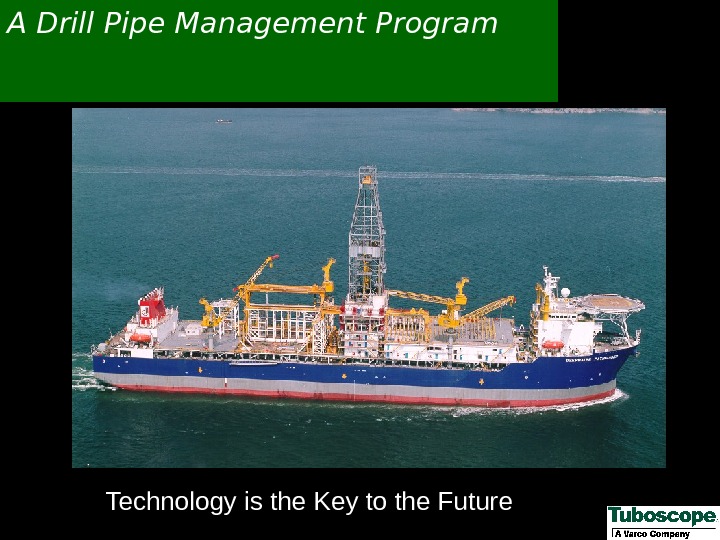
 A Drill Pipe Management Program Technology is the Key to the Future
 Why Do You Need A Drill Pipe Management Program? Drill Pipe Is Your Single Largest Investment — TAKE CARE OF IT Increase The Return On Your Investment Reduce Costly Failures Conserve Capital Enhance Your Company Image With Your Customers
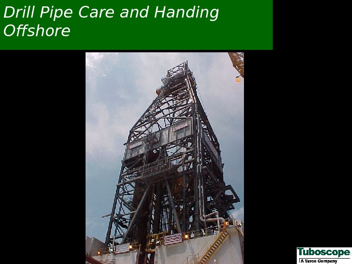
 Drill Pipe Care and Handing Offshore
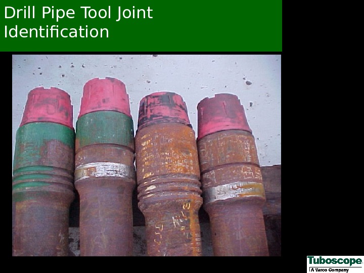
 Drill Pipe Tool Joint Identification
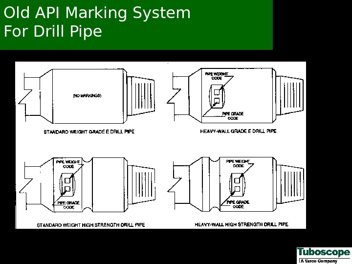
 Old API Marking System For Drill Pipe
 New API Marking System For Standard Wall Drill Pipe
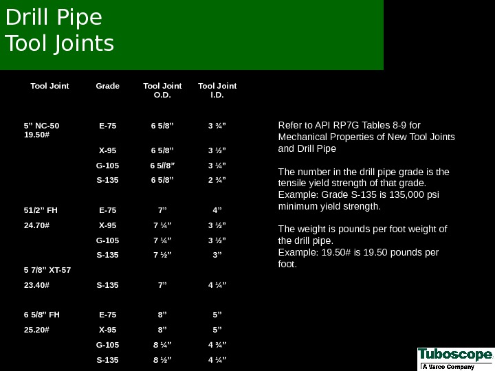
 Tool Joint Grade Tool Joint O. D. Tool Joint I. D. 5” NC-50 19. 50# E-75 6 5/8” 3 ¾” X-95 6 5/8” 3 ½” G-105 6 5//8” 3 ¼” S-135 6 5/8” 2 ¾” 51/2” FH E-75 7” 4” 24. 70# X-95 7 ¼” 3 ½” G-105 7 ¼” 3 ½” S-135 7 ½” 3” 5 7/8” XT-57 23. 40# S-135 7” 4 ¼” 6 5/8” FH E-75 8” 5” 25. 20# X-95 8” 5” G-105 8 ¼” 4 ¾” S-135 8 ½” 4 ¼” Refer to API RP 7 G Tables 8 -9 for Mechanical Properties of New Tool Joints and Drill Pipe The number in the drill pipe grade is the tensile yield strength of that grade. Example: Grade S-135 is 135, 000 psi minimum yield strength. The weight is pounds per foot weight of the drill pipe. Example: 19. 50# is 19. 50 pounds per foot. Drill Pipe Tool Joints
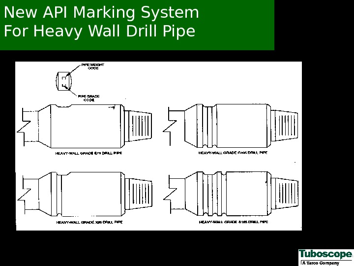
 New API Marking System For Heavy Wall Drill Pipe
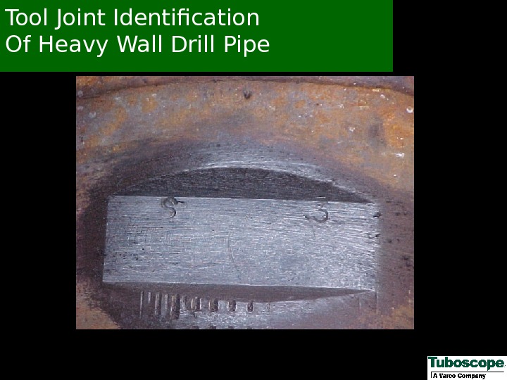
 Tool Joint Identification Of Heavy Wall Drill Pipe
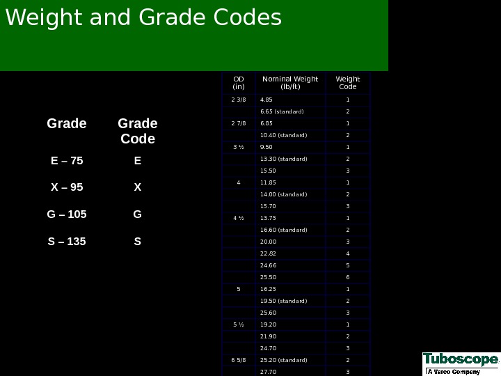
 OD (in) Nominal Weight (lb/ft) Weight Code 2 3/8 4. 85 1 6. 65 (standard) 2 2 7/8 6. 85 1 10. 40 (standard) 2 3 ½ 9. 50 1 13. 30 (standard) 2 15. 50 3 4 11. 85 1 14. 00 (standard) 2 15. 70 3 4 ½ 13. 75 1 16. 60 (standard) 2 20. 00 3 22. 82 4 24. 66 5 25. 50 6 5 16. 25 1 19. 50 (standard) 2 25. 60 3 5 ½ 19. 20 1 21. 90 2 24. 70 3 6 5/8 25. 20 (standard) 2 27. 70 3 Grade Code E – 75 E X – 95 X G – 105 G S – 135 SWeight and Grade Codes
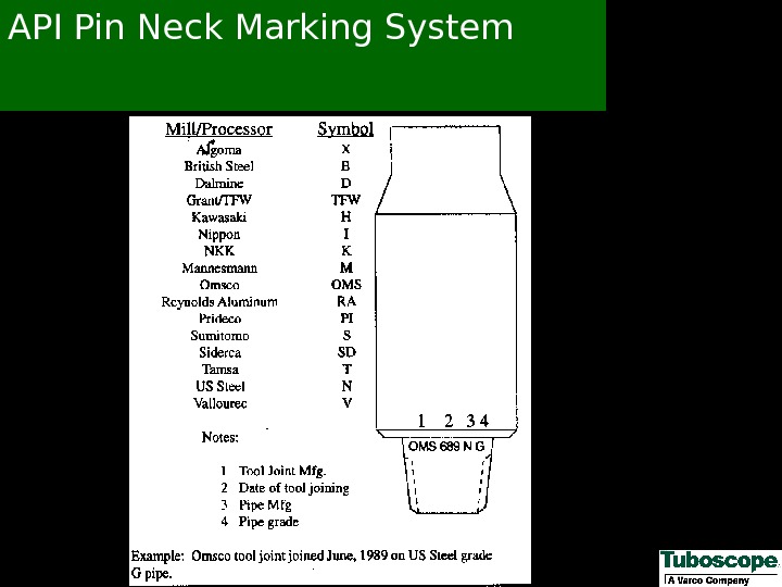
 API Pin Neck Marking System
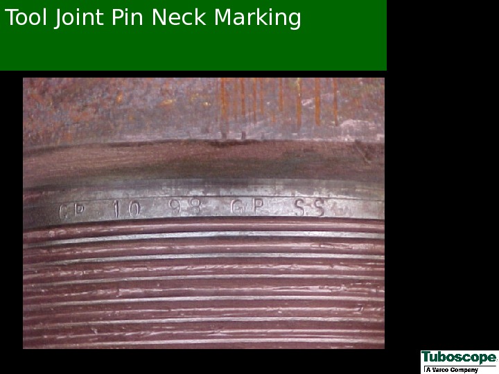
 Tool Joint Pin Neck Marking
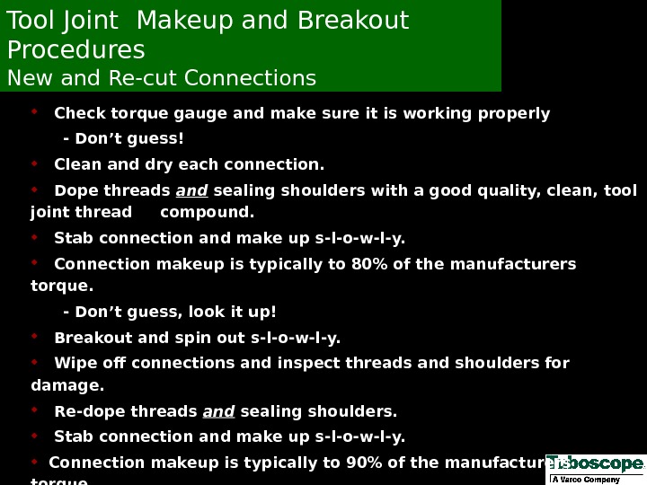
 Check torque gauge and make sure it is working properly — Don’t guess! Clean and dry each connection. Dope threads and sealing shoulders with a good quality, clean, tool joint thread compound. Stab connection and make up s-l-o-w-l-y. Connection makeup is typically to 80% of the manufacturers torque. — Don’t guess, look it up! Breakout and spin out s-l-o-w-l-y. Wipe off connections and inspect threads and shoulders for damage. Re-dope threads and sealing shoulders. Stab connection and make up s-l-o-w-l-y. Connection makeup is typically to 90% of the manufacturers torque. — Don’t guess, look it up!Tool Joint Makeup and Breakout Procedures New and Re-cut Connections
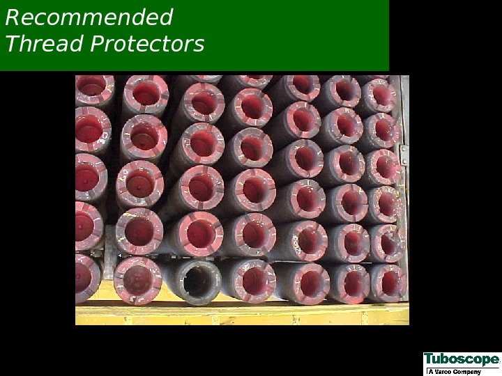
 Recommended Thread Protectors
 Be Consistent
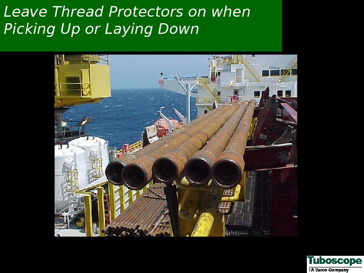
 Leave Thread Protectors on when Picking Up or Laying Down
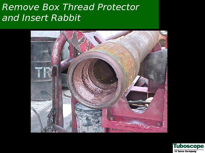
 Remove Box Thread Protector and Insert Rabbit
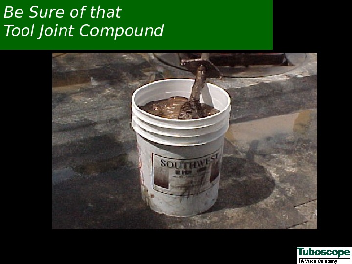
 Be Sure of that Tool Joint Compound
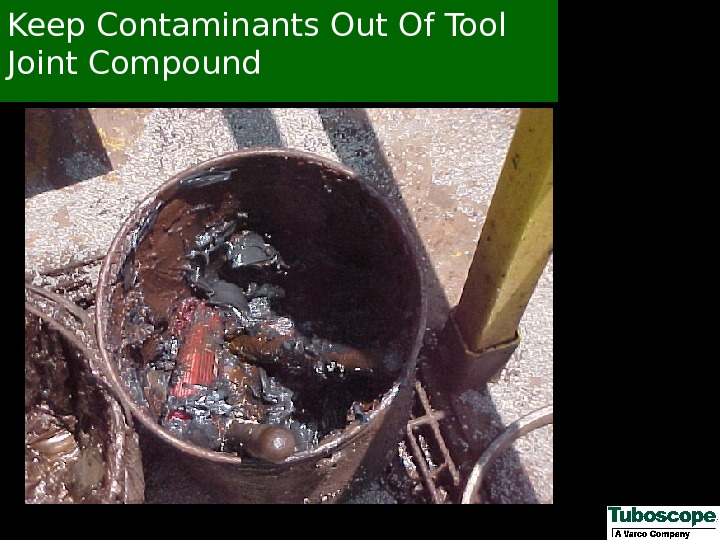
 Keep Contaminants Out Of Tool Joint Compound
 This is Not Tool Joint Compound It is Grease for Slips
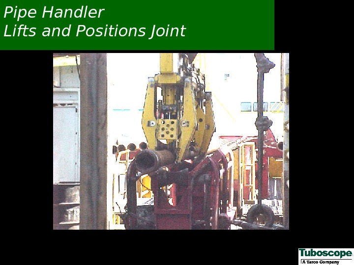
 Pipe Handler Lifts and Positions Joint
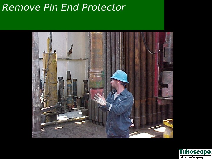
 Remove Pin End Protector
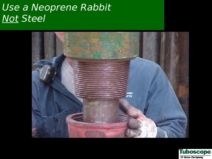
 Use a Neoprene Rabbit Not Steel
 Wipe Old Tool Joint Compound
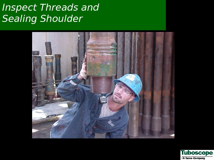
 Inspect Threads and Sealing Shoulder
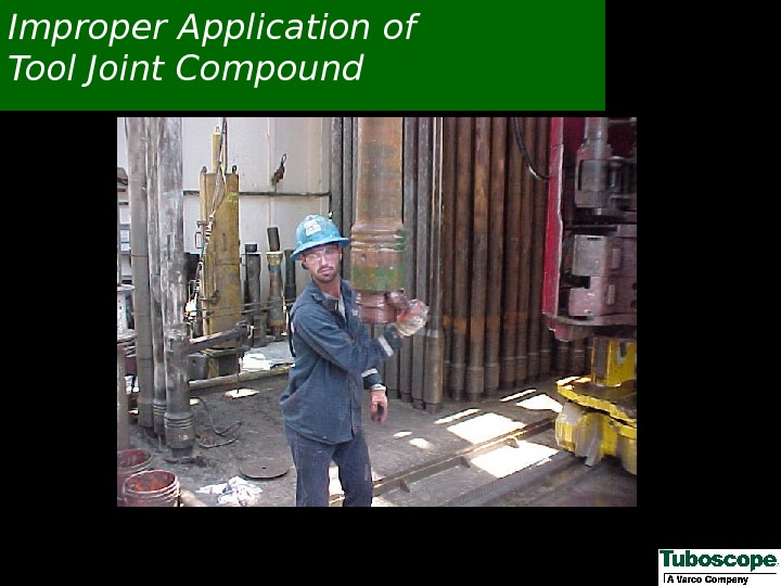
 Improper Application of Tool Joint Compound
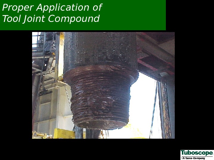
 Proper Application of Tool Joint Compound
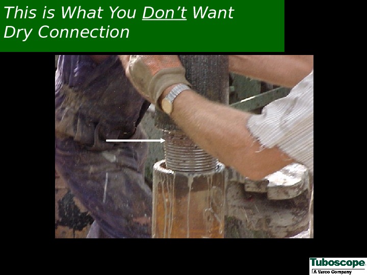
 This is What You Don’t Want Dry Connection
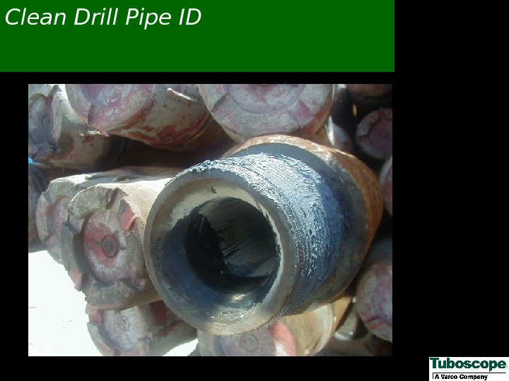
 Clean Drill Pipe I
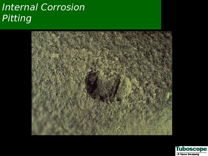
 Internal Corrosion Pitting
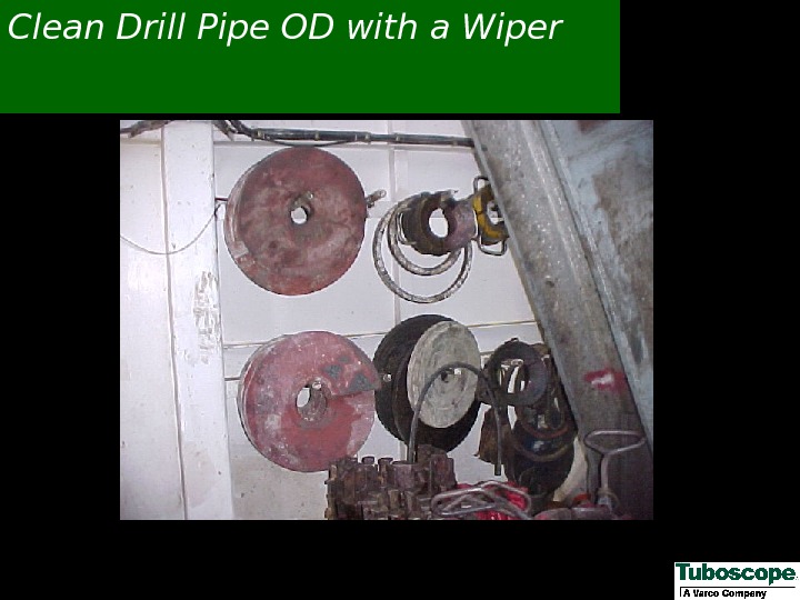
 Clean Drill Pipe OD with a Wiper
 External Corrosion Pitting
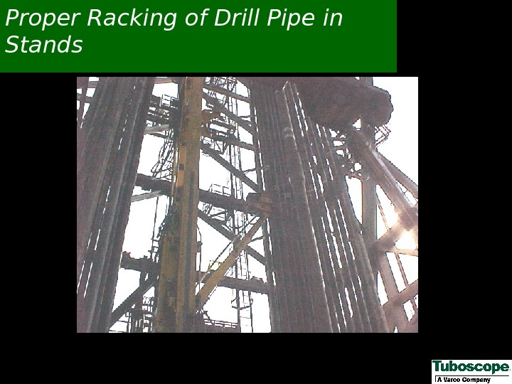
 Proper Racking of Drill Pipe in Stands
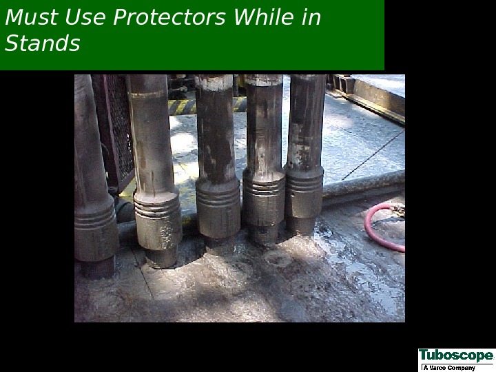
 Must Use Protectors While in Stands
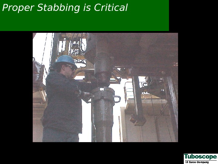
 Proper Stabbing is Critical
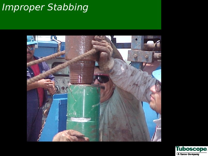
 Improper Stabbing
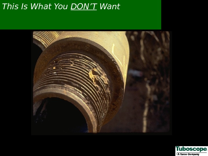
 This Is What You DON’T Want
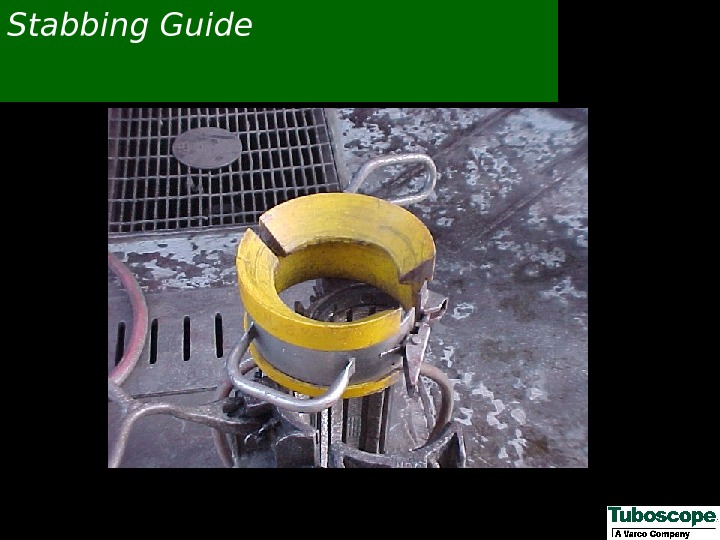
 Stabbing Guide
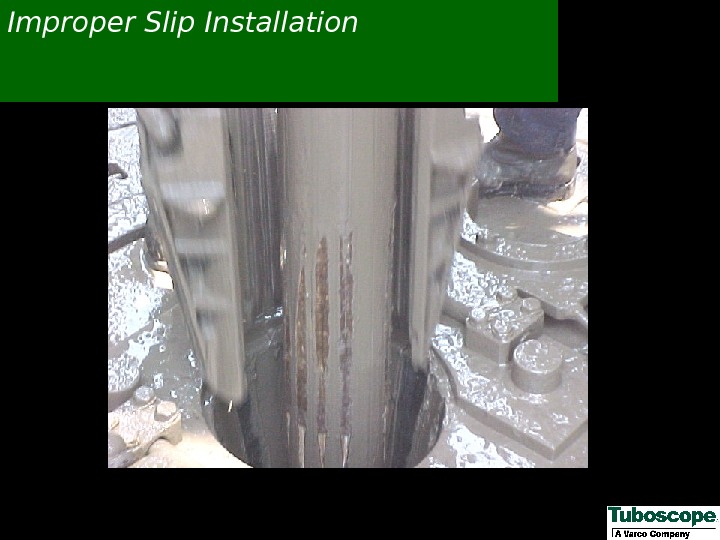
 Improper Slip Installation
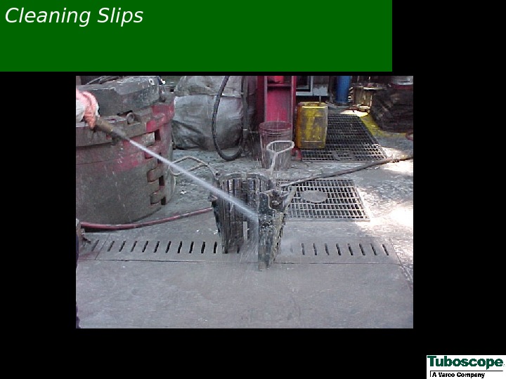
 Cleaning Slips
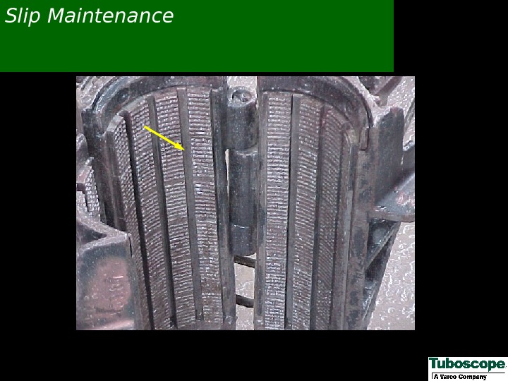
 Slip Maintenance
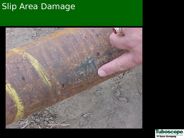
 Slip Area Damage
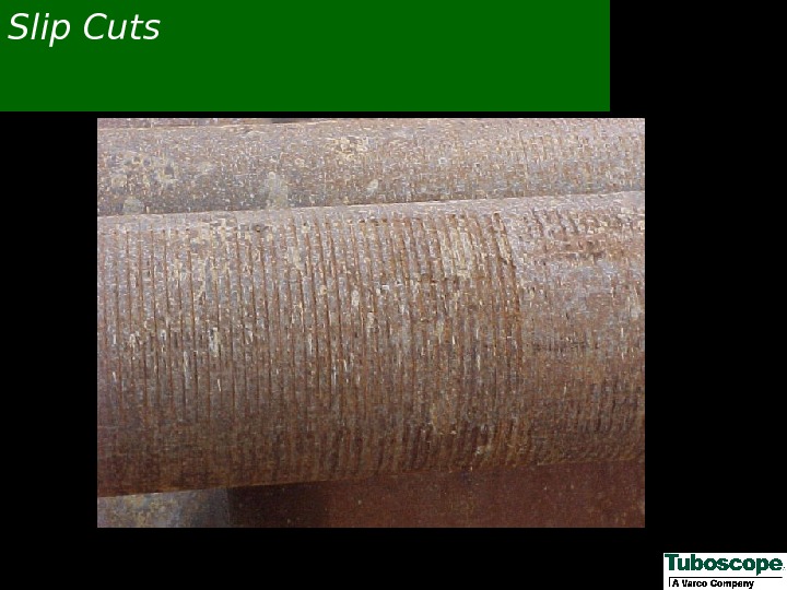
 Slip Cuts
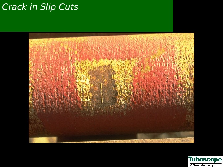
 Crack in Slip Cuts
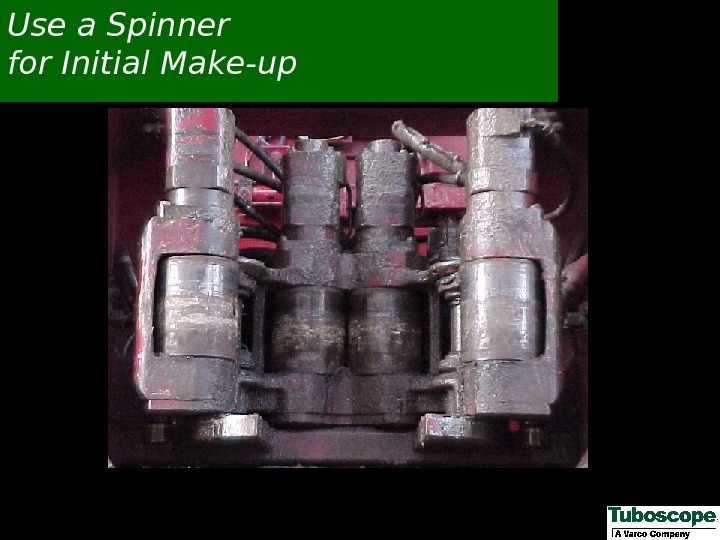
 Use a Spinner for Initial Make-up
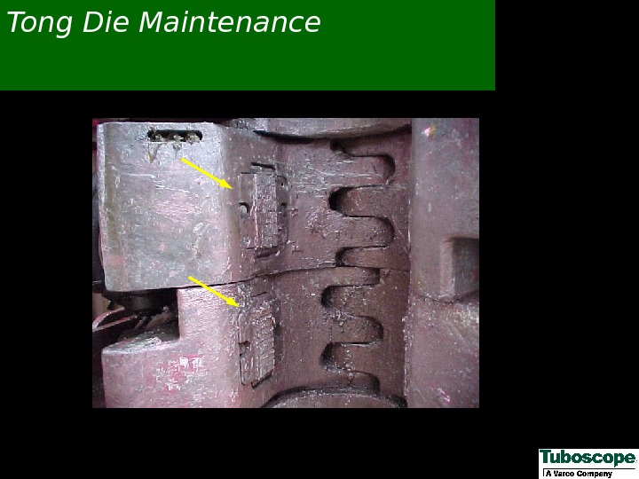
 Tong Die Maintenance
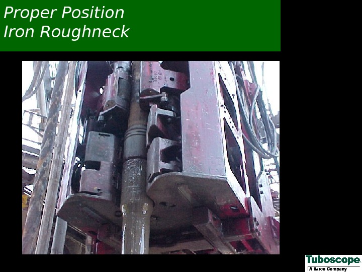
 Proper Position Iron Roughneck
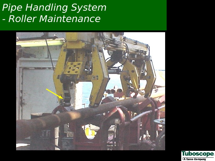
 Pipe Handling System — Roller Maintenance
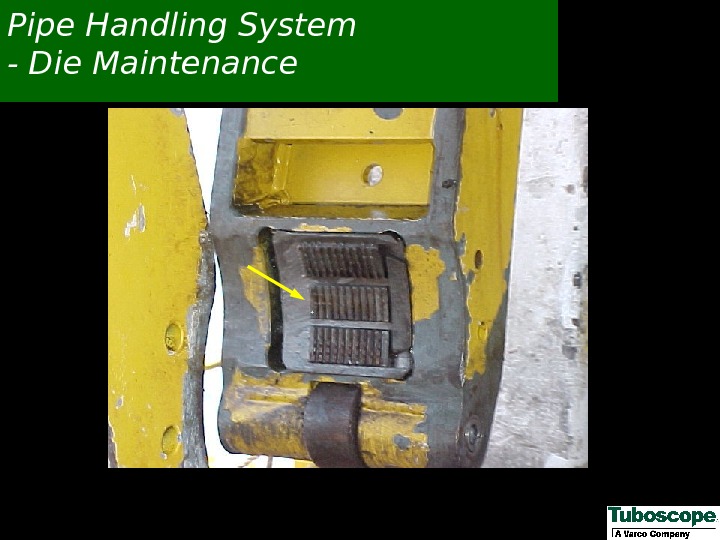
 Pipe Handling System — Die Maintenance
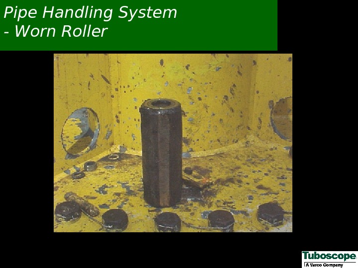
 Pipe Handling System — Worn Roller
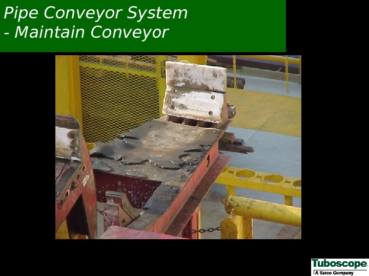
 Pipe Conveyor System — Maintain Conveyor
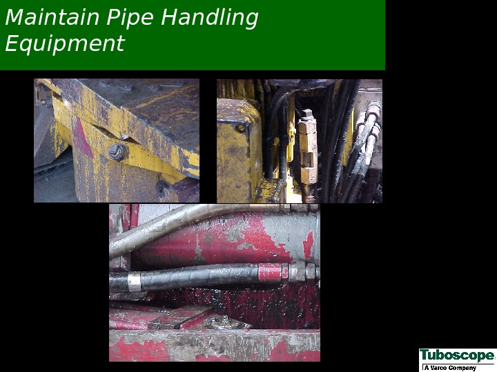
 Maintain Pipe Handling Equipment
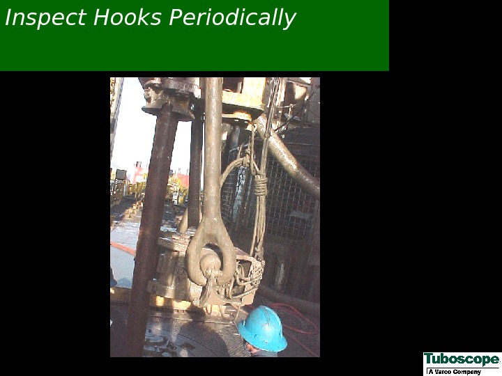
 Inspect Hooks Periodically
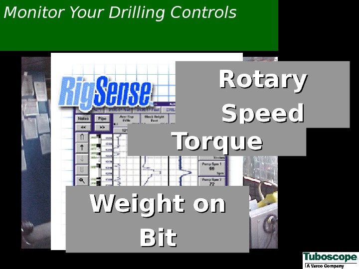
 Monitor Your Drilling Controls Rotary Speed Torque Weight on Bit
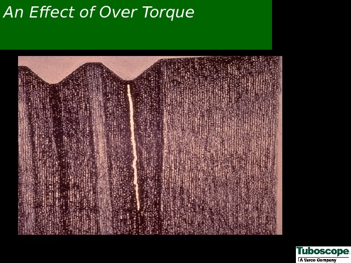
 An Effect of Over Torque
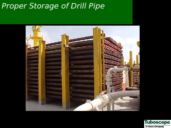
 Proper Storage of Drill Pipe
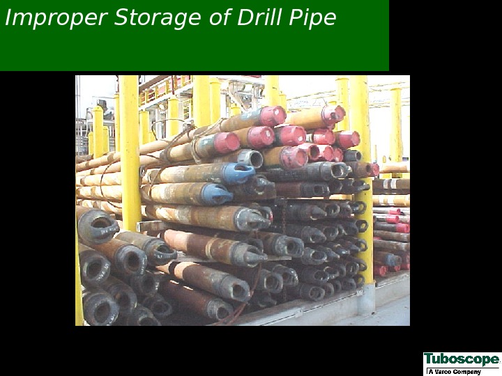
 Improper Storage of Drill Pipe
 Proper Storage of Subs
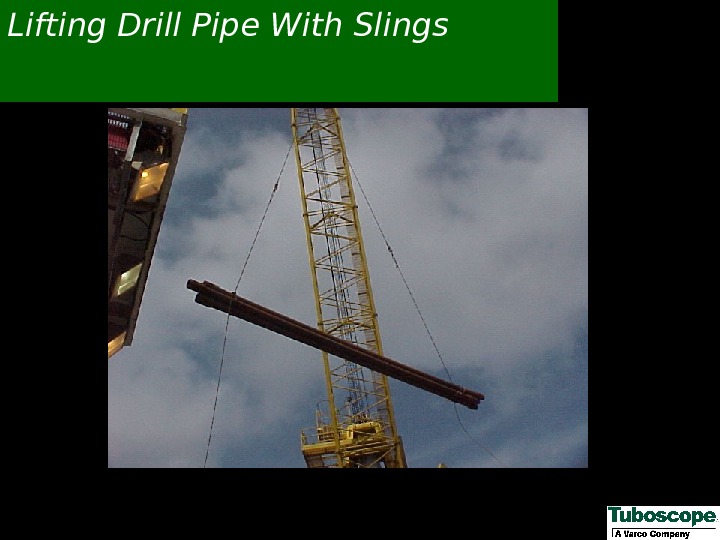
 Lifting Drill Pipe With Slings
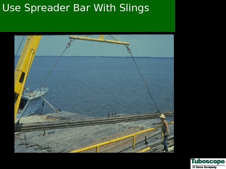
 Use Spreader Bar With Slings
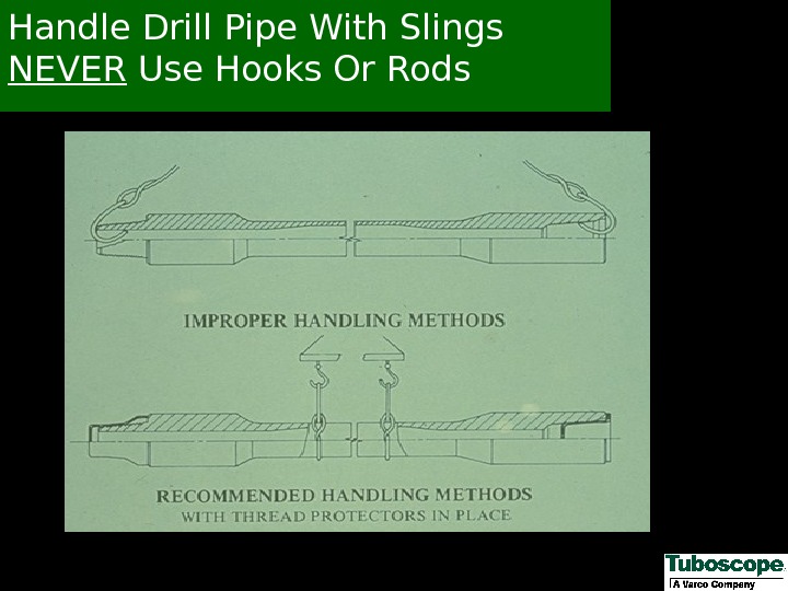
 Handle Drill Pipe With Slings NEVER Use Hooks Or Rods
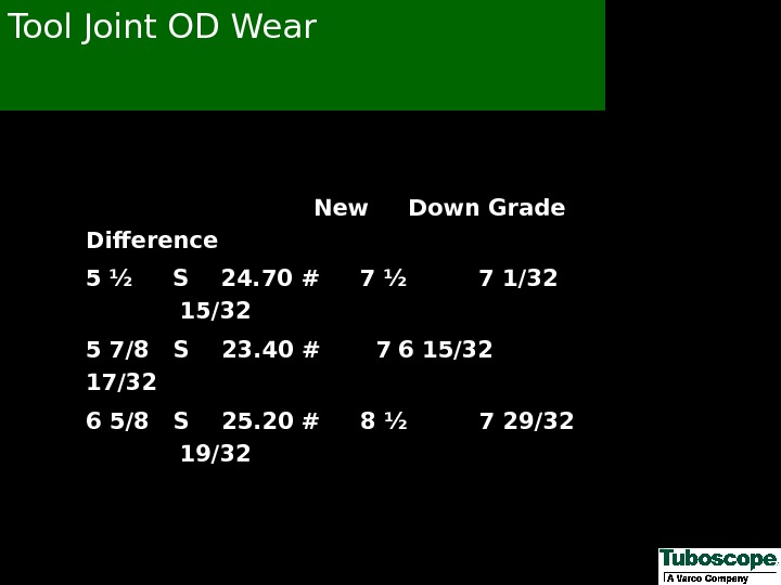
 Tool Joint OD Wear New Down Grade Difference 5 ½ S 24. 70 # 7 ½ 7 1/32 15/32 5 7/8 S 23. 40 # 7 6 15/32 17/32 6 5/8 S 25. 20 # 8 ½ 7 29/32 19/
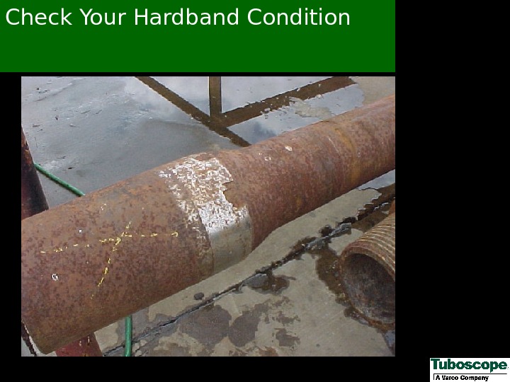
 Check Your Hardband Condition
 Date: ______ Tuboscope Inspector _______________ Rig No. : ______ Rig Location: _______ Oil Company: ________________ Description Of Drill Pipe: Size: 5 Grade: X-95 Weight: 19. 50 Connection: NC 50 Hardband Condition: Drill Pipe No. of joints requiring hardbanding : ____ Average box tool joint OD: ______ No. of joints requiring tool joint rebuild: ______ Caliper Settings For Hardbanding 3 ½”, 13. 30 & 15. 50#, NC-38 connections – 4 13/16” ** E-75, 13. 30# — 4 9/16” ** 4 ½”, 16. 60 & 20. 00#, NC-46 connections – 6 1/16” ** – ALL 5”, 19. 50 & 25. 60#, NC-50 connections – 6 7/16” ** – ALL ** Caliper settings were based on new tool joint OD less 3/16”. Field hardband units typically deposit 1/8” to 3/16” of hardband material, cumulatively, on the tool joint. . Exceeding new tool joint OD can result in fishing problems and elevator damage. Tong Space Minimums: Box Tool Joint – 9 -1/2” (includes 3” hardband allowance) Drill Collars require Hard banding – Yes No Pin Tool Joint – 6 -1/2” If yes, how many and what size No. of joints with short boxes: No. of joints with short pins: HWDP require Hard banding – Yes No Average box tool joint tong space: ______ Average pin tool joint tong space: _______Used Drill Pipe Hardband Condition Report
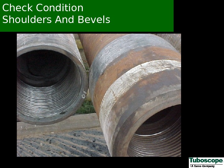
 Check Condition Shoulders And Bevels
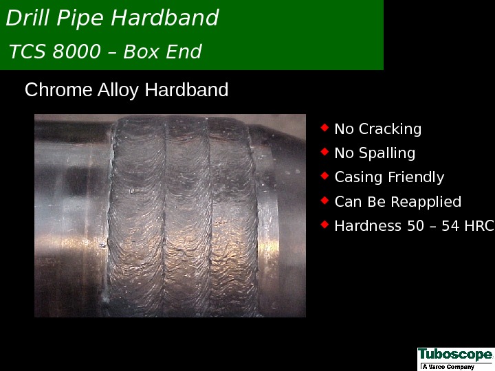
 Chrome Alloy Hardband. Drill Pipe Hardband TCS 8000 – Box End No Cracking No Spalling Casing Friendly Can Be Reapplied Hardness 50 – 54 HR
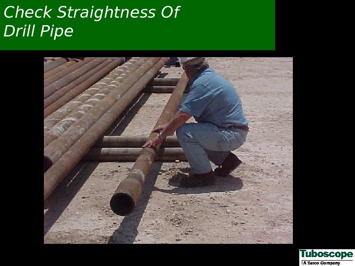
 Check Straightness Of Drill Pipe
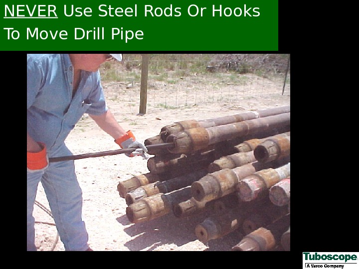
 NEVER Use Steel Rods Or Hooks To Move Drill Pipe
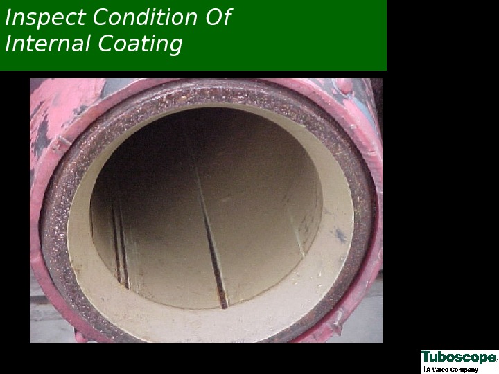
 Inspect Condition Of Internal Coating
 How To Minimize Corrosion In The Drill Stem Control the drilling fluid p. H. A p. H of 9. 5 or higher will deter the corrosion of steel in water-base systems containing dissolved O 2 Use proper inhibitors/oxygen scavengers particularly with low p. H, low solids drilling fluids. Use plastic coated pipe and a proven re-coating program. Use de-gassers/de-sanders to remove dissolved gases and abrasives. Maintain tight pump connections and reduce oxygen intake. Minimize stress concentrators such as slip/tong marks, gouges, notches, etc.
 How To Minimize Sulfide Stress Cracking In The Drill Stem When practical, maintain a p. H of 10 or higher. Chemically treat before encountering H 2 S. Use the lowest grade drill pipe that will withstand the required drilling conditions. Reduce stresses by using thicker walled components. Minimize stress concentrators. After H 2 S exposure, use care in pipe handling. Avoid sudden shocks and high loads. Use oil-based mud to create an oil-wet metal. Agents that cause corrosion in water (dissolved salts, dissolved gases, and acids) do not damage oil-wet metal.
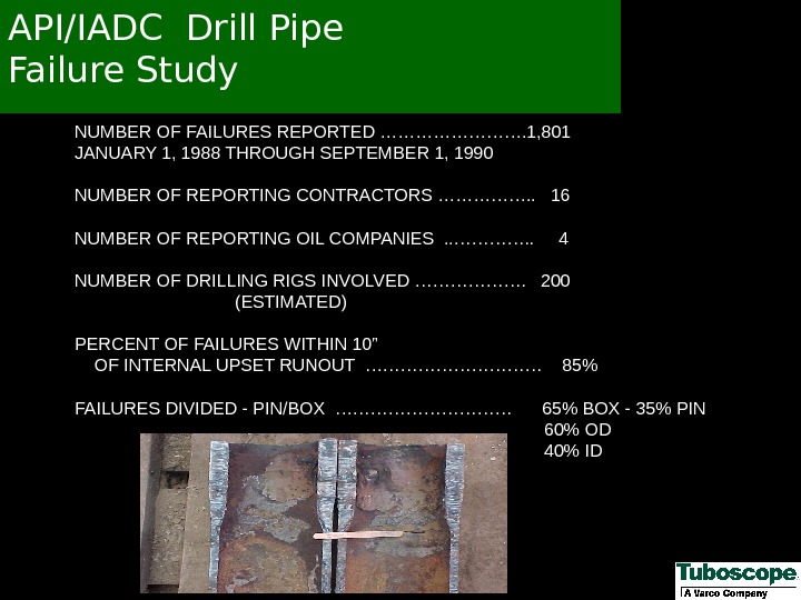
 API/IADC Drill Pipe Failure Study NUMBER OF FAILURES REPORTED …………. 1, 801 JANUARY 1, 1988 THROUGH SEPTEMBER 1, 1990 NUMBER OF REPORTING CONTRACTORS ……………. . 16 NUMBER OF REPORTING OIL COMPANIES . . …………. . 4 NUMBER OF DRILLING RIGS INVOLVED ………………. 200 (ESTIMATED) PERCENT OF FAILURES WITHIN 10” OF INTERNAL UPSET RUNOUT …………… 85% FAILURES DIVIDED — PIN/BOX …………… 65% BOX — 35% PIN 60% OD 40% I
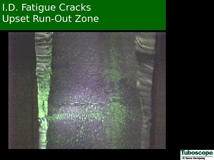
 I. D. Fatigue Cracks Upset Run-Out Zone
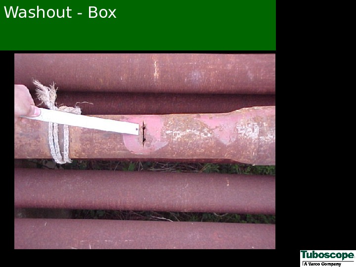
 Washout — Box
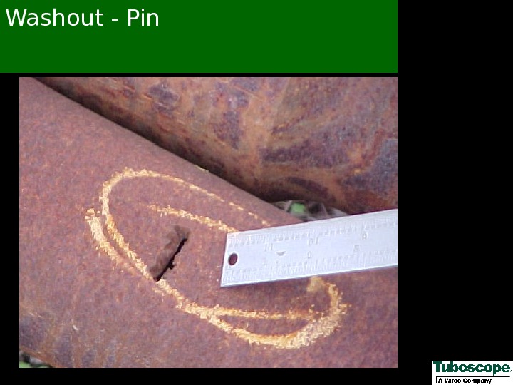
 Washout — Pin
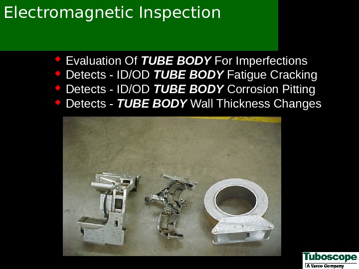
 Electromagnetic Inspection Evaluation Of TUBE BODY For Imperfections Detects — ID/OD TUBE BODY Fatigue Cracking Detects — ID/OD TUBE BODY Corrosion Pitting Detects — TUBE BODY Wall Thickness Changes
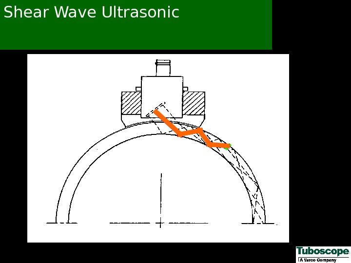
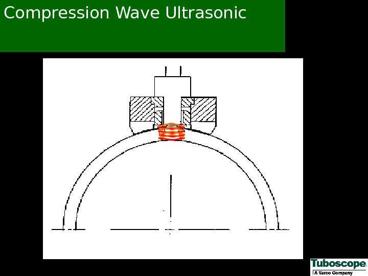
 Ultrasonic End Area Inspection Shear Wave Detection Of Fatigue Cracks In Upset Run-out Compression Wave Detection Of Corrosion Pitting In Upset Run-out Detection Of Wall Reduction In Upset Run-out
 Shear Wave Ultrasonic
 Compression Wave Ultrasonic
 Benefits Of Ultrasonic End Area Inspection Detects Minute O. D. /I. D. Fatigue Cracks Throughout The Upset Run-out Zone Detects Corrosion Pitting Throughout The Upset Run-out Zone Detects Wall Thickness Reduction Throughout The Upset Run-out Zone Reduces Used Drill Pipe Inspection Cost Capable Of Inspecting Heavy-Wall Drill Pipe
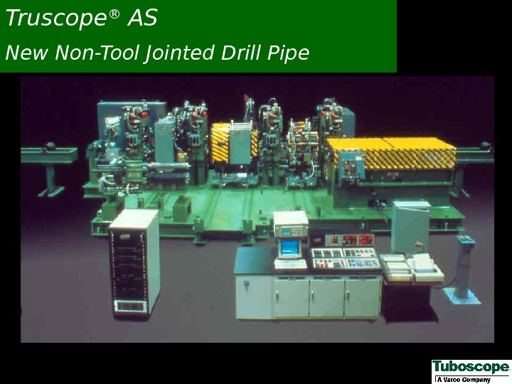
 Truscope ® AS New Non-Tool Jointed Drill Pipe
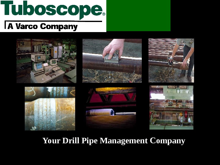
 Your Drill Pipe Management Company
 Tuboscope would like to express special thanks to both Conoco Inc. and Transocean Offshore Deepwater Drilling Inc. for providing access to the Deepwater Pathfinder Drill Ship. Thank You
 Tuboscope Drill String Services Thank You

