436e1ae2ee714b91ea6b4647bc0a20f8.ppt
- Количество слайдов: 69


3 D Morphing

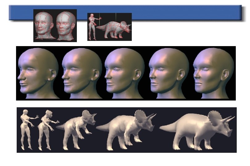
3 D preobrazba polž-žaba Demo

Področja uporabe • • Scientific Visualization Education Entertainment Computer Animation – gives the animator the ability to “fill” an animation between key-framed objects

Kako izvedemo preobrazbo • To interpolate object shapes • To interpolate object attributes including color, textures, and normal fields

Dobra preobrazba • Natural – Keep as much as possible of the two shapes during the transformation – They are subjective aesthetic criteria • Need user control – intuitive – not too heavy – can be adapted to user’s knowledge

The problem of blending two surfaces, even polyhedral ones, is not simple. In order to blend two polyhedral models, most techniques require establishing a full correspondence between their structures However, a correspondence alone does not guarantee a smooth transition from the source model to the designated model, and the vertices’ paths have to avoid troublesome situations such as self-intersections.

Klasifikacija metod • Boundary representations-based approaches • Volume-base approaches

3 D preobrazba • What is 3 D morphing ? – A 3 D model of the object is transformed from one shape into another. • Why 3 D morphing ? – Morphs are independent of viewing and lighting parameters. – View-dependent effects possible e. g. , shadows, highlights, camera can be animated during the morph. – Traditional 2 D morphs are inherently “flat” looking. • Features of a Good 3 D morphing algorithm – Conceptually Simple – Minimal topological restrictions. – Easy to user-control

3 D preobrazba krave v tigra 3 D morphing between a cow and a tiger. Note that the camera roams during the animation and the model casts a shadow that evolves according to the shape of the 3 D model. Such view-dependent effects are impossible with image-space metamorphosis.

Mehka animacija objektov • Import the tricks from traditional animation into computer animation – Give characters a pseudopersonality – Stretch and squeeze is used to highlight dynamic action such as deceleration due to collisions • shape distortion

Razlika med mehko animacijo objektov in modeliranjem • It blurs the traditional distinction between modeling and animating – a different model is created for each frame – animate the data that represents the model

3 D preobrazba Given two objects, metamorphosis involves producing a sequence of intermediate objects that gradually evolve from one object to the other.

Naivna 3 D preobrazba

Problem korespondence

Problem korespondence v 1 dimenziji

Problem korespondence v 3 dimenzijah

Preobrazba na osnovi poligonov
 vertices Other parameters (normals, textures)")
3 D model Model Polygons (triangles) vertices Other parameters (normals, textures)

Princip 3 D preobrazbe

3 d preobrazba slon žirafa 1

3 d preobrazba slon-žirafa 2

Omejitve preobrazbe, temelječe na poligonih

B-rep Based 3 D morphing • Polyhedral Morphing Using Feature-Based Surface Decomposition • A. Gregory, A. State, M. C. Lin, D. Manocha, and M. A. Livingston. Interactive surface decomposition for polyhedral morphing. The Visual Computer (1999) 15: 453 -470

Postopek 3 D preobrazbe Two Input Polyhedra User Specify Correspondence Edit trajectories Compute merged polyhedron Interpolate trajectories Morphing sequence

Arhitektura sistema

Specificiranje korespondence

Kaj mora narediti uporabnik • The users only need to specify a few corresponding pairs of features on the two polyhedra. • They can then specify the trajectories along which these features travel during the morph using Bezier curves, as shown below

Skupna povezljivost
")
Prevleka (Overlay)

Preslikava na kroglo

Predelava mreže z delitvijo

Primerjava metod

Računanje korespondence • Feature-Nets decompose input polyhedra into morphing patches • For each corresponding Morphing Patch pair: – map both onto a 2 D polygon – merge the vertex-edge graphs – reconstruct the facets
 B (House)")
Računanje korespondence A (Igloo) B (House)

Računanje korespondence Patch A Patch B Extremal Vertices

Preslikava Patch A Patch B
 Patch A Patch B")
Zlivanje (Merging) Patch A Patch B

Rekonstrukcija

Končana korespondenca

Specifikacija trajektorij preobrazbe

Interpolacija krivulj

Omejitve interpolacije Reeves, William T. “Inbetweening for Computer Animation Utilizing Moving Point Constraints” SIGGRAPH 81, pp. 263 -269

Volume-base Approaches • D. Cohen-Or, D. Levin, A. Solomovoci. Threedimensional distance field metamorphosis. ACM Trans. Graphics 17: 116 -141, 1998 • http: //www. math. tau. ac. il/~levin/

Tehnike • The objects are expressed as level sets of distance functions • Two steps: – Warp: deform the 3 D space in order to make the two objects to be morphed coincide as much as possible – Interpolation: linear interpolate distance fields deformed by the warp
 points in each")
Interakcija • The user interface allows to select feature (or anchor) points in each voxelized object space and map the anchor points of the source object to the anchor points of the target object

Given two or more objects of general topology, intermediate objects are constructed by a distance field metamorphosis. In the presented method the interpolation of the distance field is guided by a warp function controlled by a set of corresponding anchor points. Some rules for defining a smooth least-distorting warp function are given. To reduce the distortion of the intermediate shapes, the warp function is decomposed into a rigid rotational part and an elastic part.

The distance field interpolation method is modified so that the interpolation is done in correlation with the warp function. The method provides the animator with a technique that can be used to create a set of models forming a smooth transition between pairs of a given sequence of keyframe models. The advantage of the approach is that it is capable of morphing between objects having a different topological genus where no correspondence between the geometric primitives of the models needs to be established. The desired correspondence is defined by an animator in terms of a relatively small number of anchor points.
")
3 D Shape Interpolation (1)

Animating Shape Change • Per-vertex animation curves – beginning and end known • Simply change parameters with time – Twist angle – Scaling constant – Seed vertex position • All standard rules apply – Curve smoothness, motion controls, etc.

3 D Shape Interpolation Approaches • • • Matching topology Star shaped polyhedra Star shaped with respect to an axis General map to sphere Merging topologies) Recursive subdivision)

Matching Topology same meshes with same vertex-edge topology

Matching Topology different meshes with same vertex-edge topology N = 5 k vertices

Matching Topology N = 5 k vertices 5 7 2 7 5 2
 Texture (u, v) 5 7 2 7")
Matching Topology Vertex Normal Material (diffuse, specular) Texture (u, v) 5 7 2 7 5 2
 Sequential FFD")
Matching Topology Used in Free From Deformation (FFD) Sequential FFD

Matching Topology Hierarchical FFD

Matching Topology FFD and Animation

Matching Topology FFD and Articulated Joints

Light Field Morphing A general framework for image-based 3 D morphing – Enables morphing between image-based objects – 3 D morphing without modeling – Suitable for objects with complex surface properties (e. g. , fur, subsurface scattering, hypertexture)

Morphing = Correspondence • Image morphing = 2 D pixel correspondence • Geometry-based 3 D morphing = 3 D vertex correspondence • Light field morphing = 4 D ray correspondence

Contributions • A UI for specifying features in 4 D ray space • Ray-space warping – Handling visibility changes due to object shape change

Pregled UI Component LF 0 Specifying features LF 1 LF 0 with features LF 1 with features Light field warping Warped LF 0 Warped LF 1 Blending Morphed LF

Specifying Features • Feature points – 3 D points on object surface – Specified by manual correspondence guided by epipolar geometry

Specifying Features • Feature lines • Feature polygons – Non-planar, but relatively flat & w/o self-occlusion – Necessary only in areas with visibility changes
")
Specifying Features • No 3 D reconstruction from feature polygons • Background pixel (ray) • – Pixels (rays) with no visibility changes – Morphing controlled by background edges Background edges are key-framed

Overview Morphing Component LF 0 with features LF 0 Specifying features Warped LF 0 Light field warping LF 1 with features LF 1 Feature polygon 2 . . . Feature polygon n Morphed LF Warped LF 1 Feature polygon 1 LF with features Blending Ray bundle 1 Computing visibility map Ray bundle 2 . . . Ray bundle n Ray space warping Warped LF

Global Visibility Map • GVM describes the visibility of feature polygons in each view • Key to visibility processing • GVM = A light field of false colors, associating each ray with a feature polygon

Computing GVM • Rendering a set of non-planar but relatively flat polygons – No self-occlusions – Two-pass Open. GL rendering with stencil buffer • Trade off: planar vs non-planar feature polygons
436e1ae2ee714b91ea6b4647bc0a20f8.ppt