
1 System Principal Operating panel APP I


- Размер: 6 Mегабайта
- Количество слайдов: 23
Описание презентации 1 System Principal Operating panel APP I по слайдам
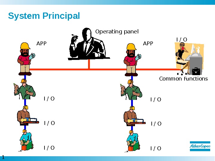
1 System Principal Operating panel APP I / O Common Functions. APP I / O
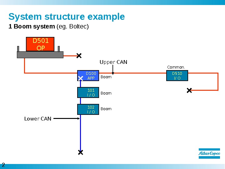
2 System structure example 1 Boom system (eg. Boltec) Upper CAN D 510 I/ OCommon. D 501 OP D 100 APP Boom 101 I / O Boom 102 I / O Lower CAN
3 System structure example 2 Boom system (eg L 2 C) Upper CAN D 510 I/ OCommon. D 501 OP D 100 APP Boom 101 I / O Boom 102 I / O Lower CAN
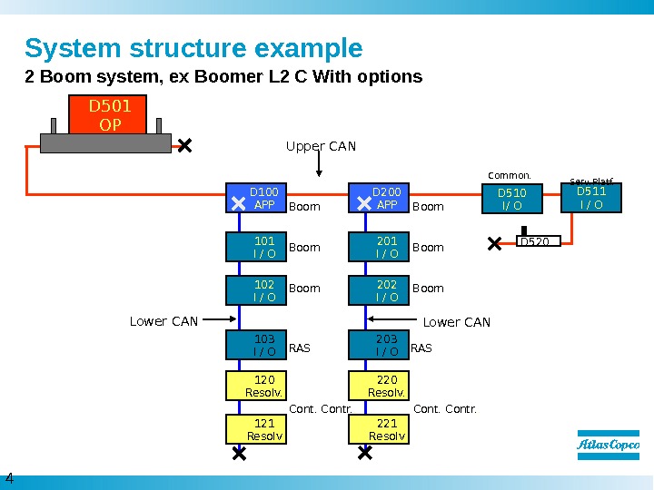
4 Lower CANSystem structure example Upper CAND 501 OP Boom. D 2 00 APPD 100 APP Boom 2 02 I / O 2 01 I / O 102 I / O 101 I / O Contr. . 2 20 Resolv. 2 21 Resolv 120 Resolv. 121 Resolv D 511 I / OServ. Platf. D 510 I/ OCommon. D 520 RAS 2 03 I / O 103 I / O RAS 2 Boom system, ex Boomer L 2 C With options
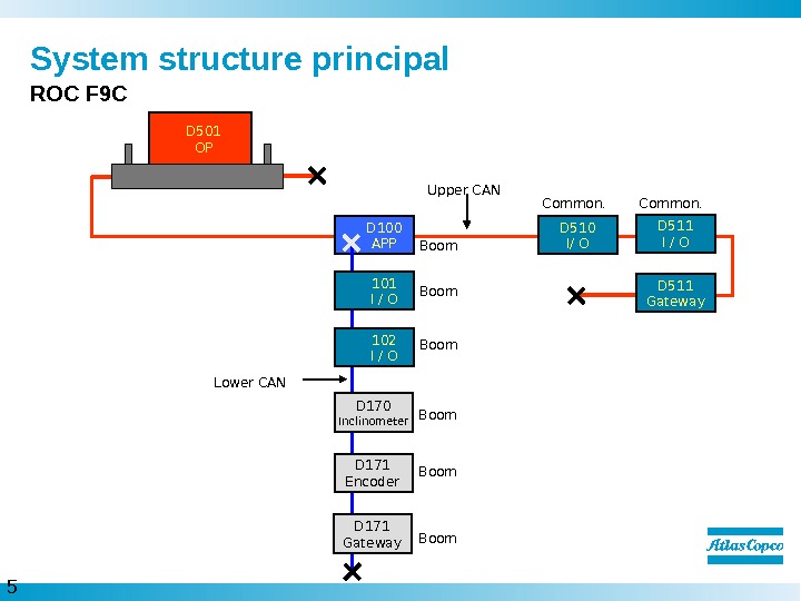
5 System structure principal ROC F 9 C Upper CAN D 100 APP Boom Lower CAN Boom 102 I / O 101 I / O D 511 I / OCommon. D 510 I/ OCommon. D 511 Gateway D 170 Inclinometer D 171 Encoder D 171 Gateway Boom. D 501 OP
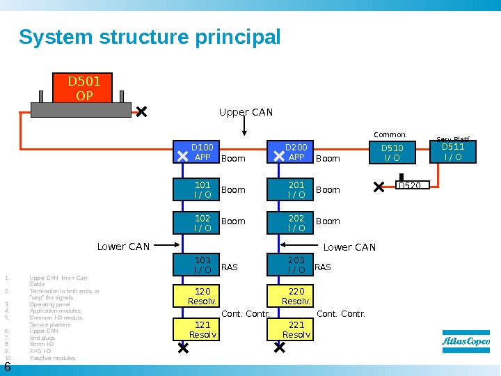
6 Lower CANSystem structure principal Upper CAND 501 OP Boom. D 2 00 APPD 100 APP Boom 2 02 I / O 2 01 I / O 102 I / O 101 I / O Contr. . 2 20 Resolv. 2 21 Resolv 120 Resolv. 121 Resolv 1. Upper CAN line = Can Cable 2. Termination in both ends, to “stop” the signals 3. Operating panel 4. Application modules 5. Common I-O module, Service platform 6. Upper CAN 7. End plugs 8. Boom I-O 9. RAS I-O 10. Resolver modules D 511 I / OServ. Platf. D 510 I/ OCommon. D 520 RAS 2 03 I / O 103 I / O RAS
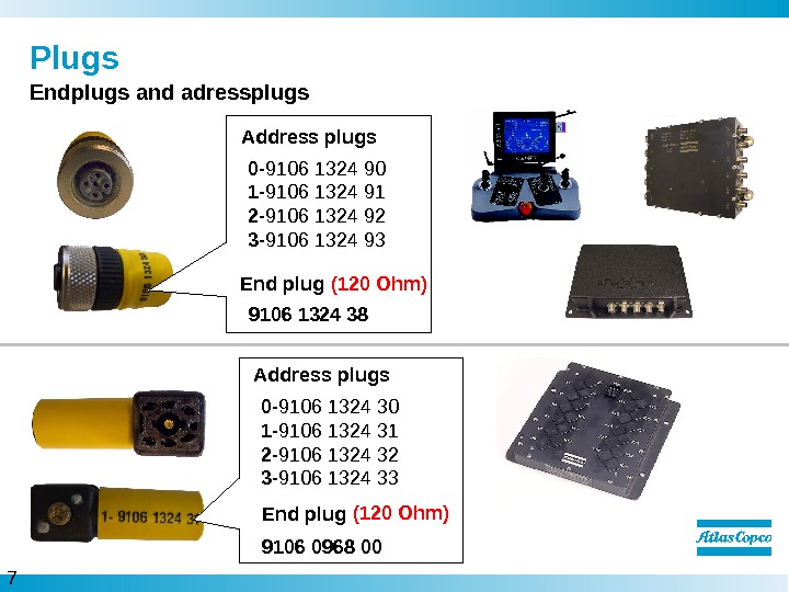
7 Plugs Endplugs and adressplugs 9106 0968 000 — 9106 1324 30 1 — 9106 1324 31 2 — 9106 1324 32 3 — 9106 1324 33 Address plug s End plug (120 Ohm)9106 1324 38 End plug 0 — 9106 1324 90 1 — 9106 1324 91 2 — 9106 1324 92 3 — 9106 1324 93 Address plug s (120 Ohm)
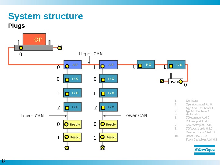
8 Resolv. Lower CANI / OSystem structure Plugs Upper CAN I / OI/ OOP APPAPP I / O 0 1. End plugs 2. Operators panel Ad 0 3. App Add 0 for boom 1, 4. App Add 1 for boom 2 5. Master add 3 6. I/O common Add 0 I/O serv plat Add 1. 7. Lever serv plat Add 0 8. I/O boom 1 Add 0, 1, 2 9. Resolver boom 1 Add 0, 1 10. Boom 2 I/O 0, 1, 2 Boom 2 resolver Add 0,
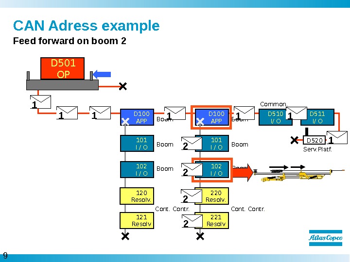
9 Boom. CAN Adress example Feed forward on boom 2 D 510 I/ OCommon. D 501 OP D 100 APP Boom 101 I / O Boom 102 I / O D 100 APP Boom 101 I / O 102 I / O Contr. . 2 20 Resolv. 2 21 Resolv 120 Resolv. 121 Resolv Serv. Platf. D 520 D 511 I/ O
1 0 Connections on modules Connections – X 1 Power supply – X 2 CAN in/out (Lower CAN Communication) – X 3 CAN in/out (Lower CAN Communication) – X 4 CAN in/out (Upper Communication) – X 5 Address plug Diodes – D 1 Power Supply – D 2 Lower CAN Status – D 3 Lower CAN Power Supply – D 4 Upper CAN Status – D 5 CAN 1 Power supply – D 6 Module status. Application module/Master module/CCIX 5 X 4 X 3 X 2 X 1 D 6 D 4 D 2 D 5 D 3 D 1 D 5 D 3 D 1 X 5 X 4 X 3 X 2 X
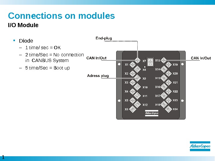
1 1 Connections on modules I/O Module Diode – 1 time/ sec = OK – 2 time/Sec = No connection in CANBUS System – 5 time/Sec = Boot up
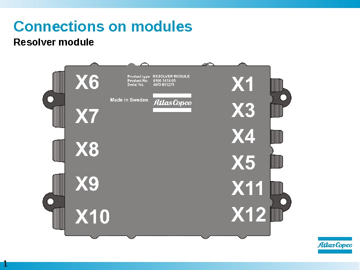
1 2 Connections on modules Resolver module
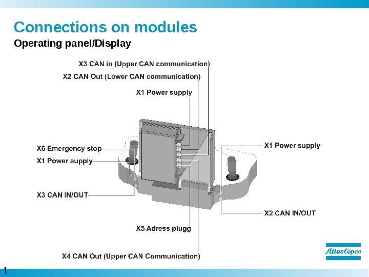
1 3 Connections on modules Operating panel/Display
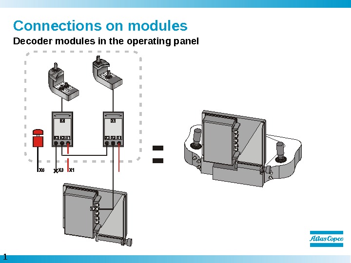
1 4 Connections on modules Decoder modules in the operating panel=
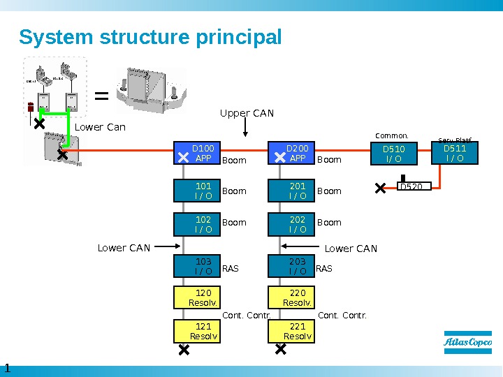
1 5 System structure principal Lower CANUpper CAN Boom. D 2 00 APPD 100 APP Boom 2 02 I / O 2 01 I / O 102 I / O 101 I / O Contr. . 2 20 Resolv. 2 21 Resolv 120 Resolv. 121 Resolv D 511 I / OServ. Platf. D 510 I/ OCommon. D 520 RAS 2 03 I / O 103 I / O RASLower Can =
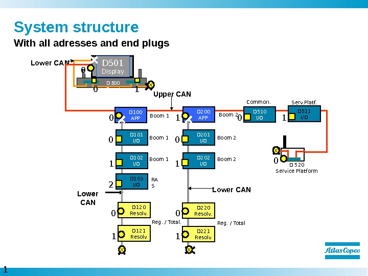
1 6 System structure With all adresses and end plugs D 500 Panel. D 501 Display. Lower CAN Upper CAN D 100 APP Boom 1 Lower CAN Boom 1 D 102 I/OD 101 I/O D 2 00 APP Boom 2 Lower CAN Boom 2 D 2 02 I/OD 2 01 I/O D 510 I/OCommon. D 103 I/O RA S D 511 I/OServ. Platf. D 520 Service Platform Reg. / Total. D 120 Resolv. D 121 Resolv Reg. / Total. D 2 20 Resolv. D 2 21 Resolv
1 7 CAN Power supply Principal of fuses to the modules
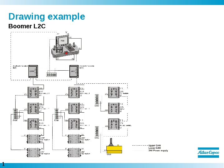
1 8 Drawing example Boomer L
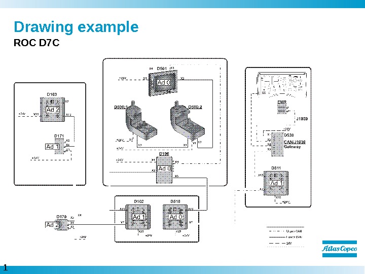
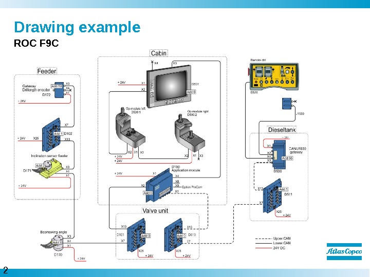
1 9 Drawing example RO
2 0 Drawing example RO
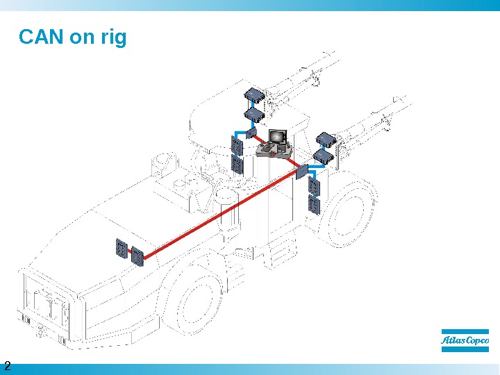
2 1 CAN on rig Boomer L
2 2 We are committed to your superior productivity through interaction and innovation.