
1 Описание двигателя Общие сведения – V


- Размер: 11.3 Mегабайта
- Количество слайдов: 87
Описание презентации 1 Описание двигателя Общие сведения – V по слайдам
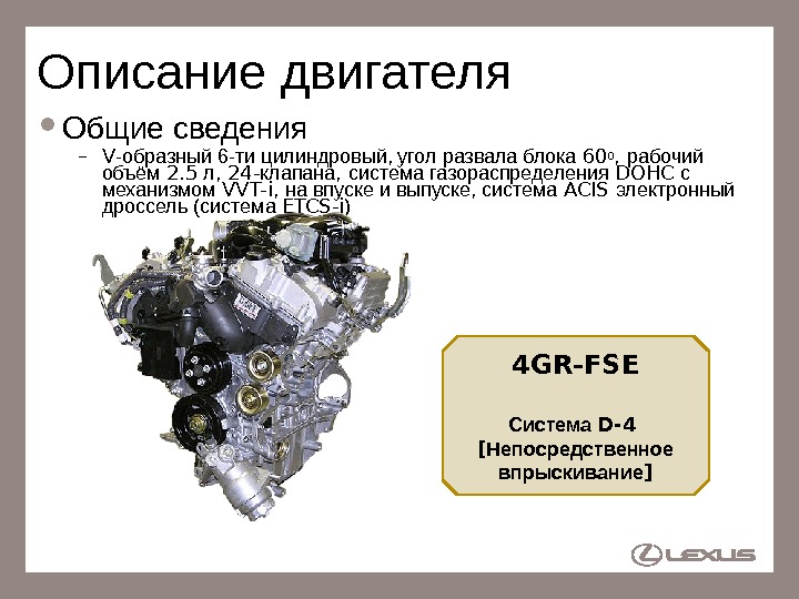
1 Описание двигателя Общие сведения – V -образный 6 -ти цилиндровый, угол развала блока 600 , рабочий объём 2. 5 л , 24 — клапана , система газораспределения DOHC с механизмом VVT-i, на впуске и выпуске, система ACIS электронный дроссель (система ETCS-i ) 4 GR-FSE Система D-4 [ Непосредственное впрыскивание ]
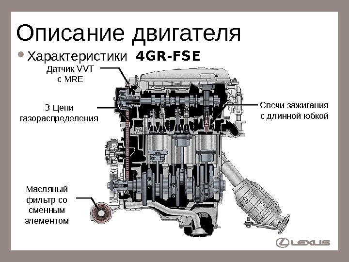
2 Описание двигателя Характеристики 4 GR-FSE 3 Цепи газораспределения Свечи зажигания с длинной юбкой Масляный фильтр со сменным элементом Датчик VVT с MR
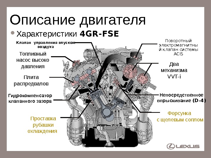
3 Описание двигателя Характеристики 4 GR-FSE Два механизма VVT-i Проставка рубашки охлаждения Гидрокомпенсатор клапанного зазора Поворотный электромагнитны й клапан системы ACIS Плита распредвалов Клапан управления впуском воздуха Топливный насос высоко давления Непосредственное впрыскивание (D-4) Форсунка с щелевым соплом
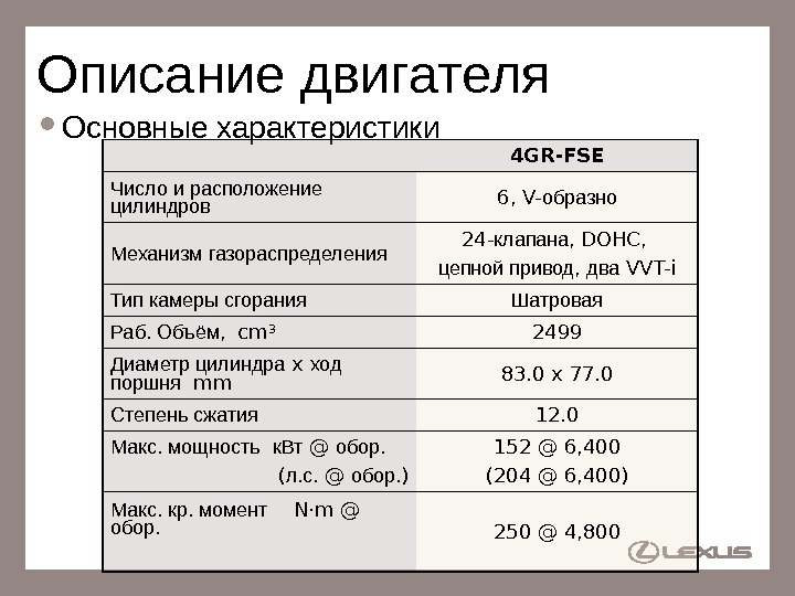
4 Описание двигателя Основные характеристики 4 GR-FSE Число и расположение цилиндров 6, V- образно Механизм газораспределения 24 — клапана, DOHC, цепной привод , два VVT-i Тип камеры сгорания Шатровая Раб. Объём, cm 3 2499 Диаметр цилиндра x ход поршня mm 83. 0 x 77. 0 Степень сжатия 12. 0 Макс. мощность к. Вт @ обор. ( л. с. @ обор. ) 152 @ 6, 400 (204 @ 6, 400) Макс. кр. момент N·m @ обор. 250 @ 4,
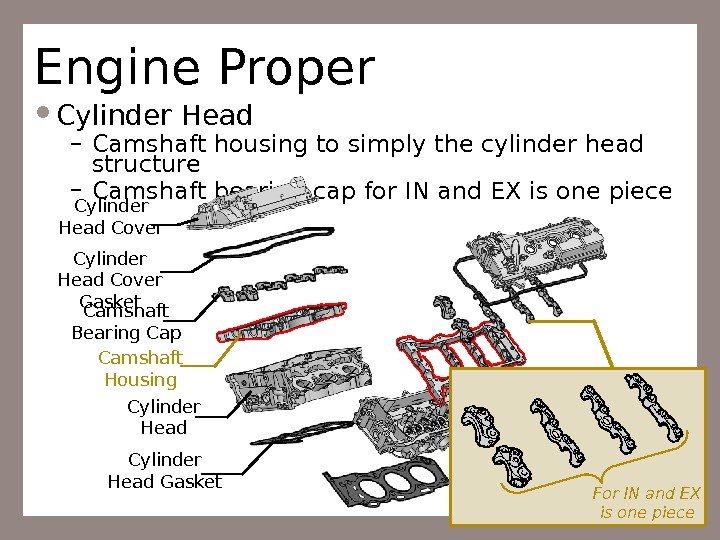
5 Engine Proper Cylinder Head – Camshaft housing to simply the cylinder head structure – Camshaft bearing cap for IN and EX is one piece Cylinder Head Cover Gasket Camshaft Bearing Cap Camshaft Housing Cylinder Head Gasket For IN and EX is one piece
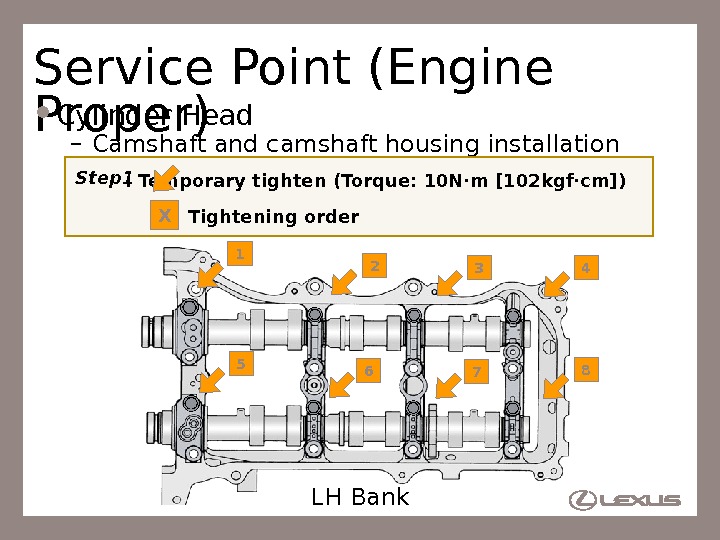
6 Service Point (Engine Proper) Cylinder Head – Camshaft and camshaft housing installation 1 2 3 4 5 6 7 8 LH Bank. Step 1 : Temporary tighten (Torque: 10 N·m [102 kgf·cm]) : Tightening order. X
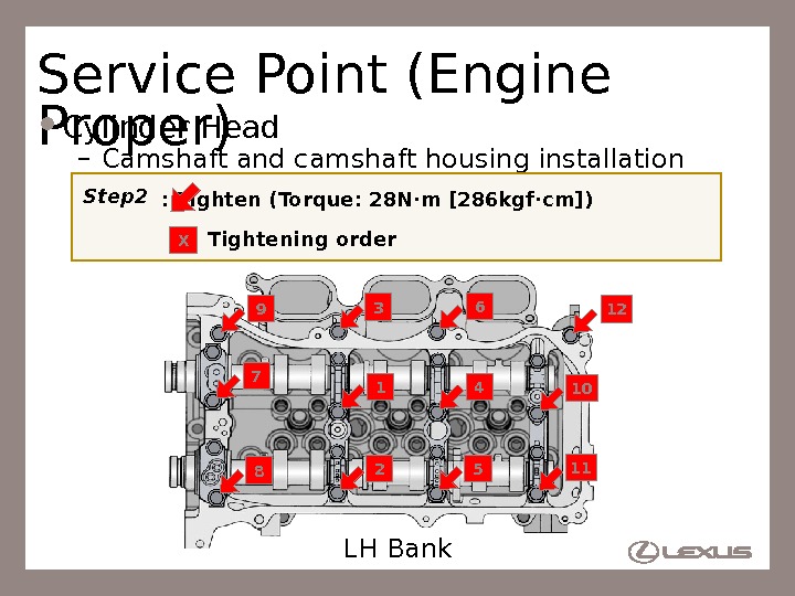
7 Service Point (Engine Proper) Cylinder Head – Camshaft and camshaft housing installation 13 2 4 5 6 87 9 10 11 12 LH Bank. Step 2 : Tighten (Torque: 28 N·m [286 kgf·cm]) : Tightening order X
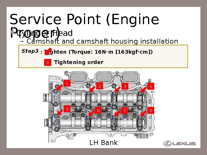
8 Service Point (Engine Proper) Cylinder Head – Camshaft and camshaft housing installation 1 2 3 4 5 6 7 8 LH Bank. Step 3 : Tighten (Torque: 16 N·m [163 kgf·cm]) : Tightening order X
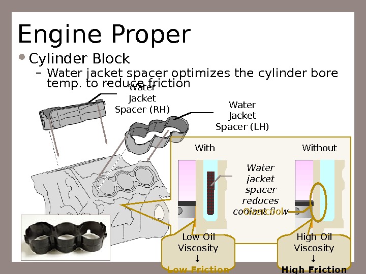
9 Engine Proper Cylinder Block – Water jacket spacer optimizes the cylinder bore temp. to reduce friction Water Jacket Spacer (LH)Water Jacket Spacer (RH) Water jacket spacer reduces coolant flow. Without Overcool Low Oil Viscosity Low Friction High Oil Viscosity High Friction
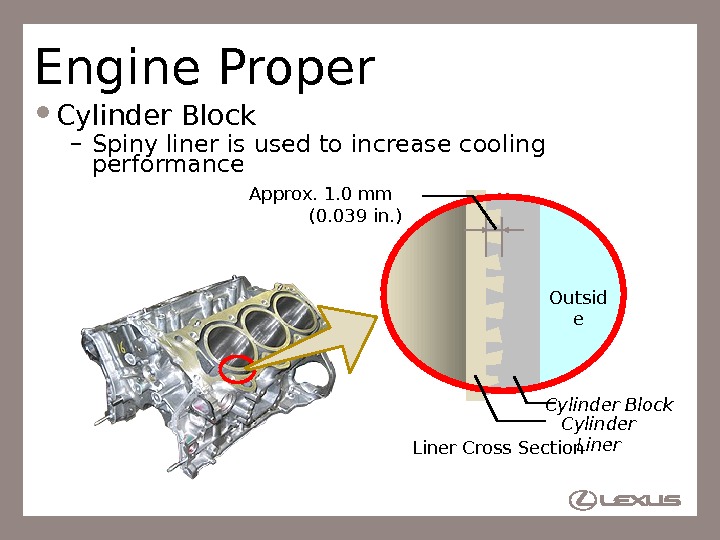
10 Engine Proper Cylinder Block – Spiny liner is used to increase cooling performance Approx. 1. 0 mm (0. 039 in. ) Liner Cross Section Outsid e Cylinder Liner. Cylinder Block
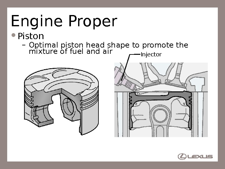
11 Engine Proper Piston – Optimal piston head shape to promote the mixture of fuel and air Injector
12 Engine Proper Bearing – Bearing without bearing claw is used for crankshaft bearings and connecting rod bearings Without bearing claw
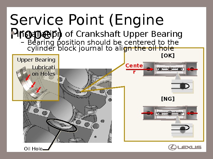
13 Service Point (Engine Proper) Installation of Crankshaft Upper Bearing – Bearing position should be centered to the cylinder block journal to align the oil hole Oil Hole. Upper Bearing [OK] [NG]Lubricati on Holes Cente r
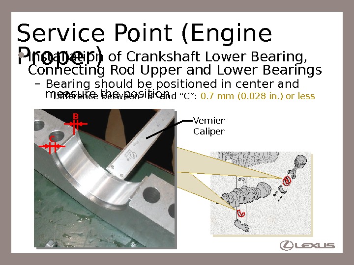
14 Service Point (Engine Proper) Installation of Crankshaft Lower Bearing, Connecting Rod Upper and Lower Bearings – Bearing should be positioned in center and measure the position Difference Between “B” and “C”: 0. 7 mm (0. 028 in. ) or less Vernier Caliper.
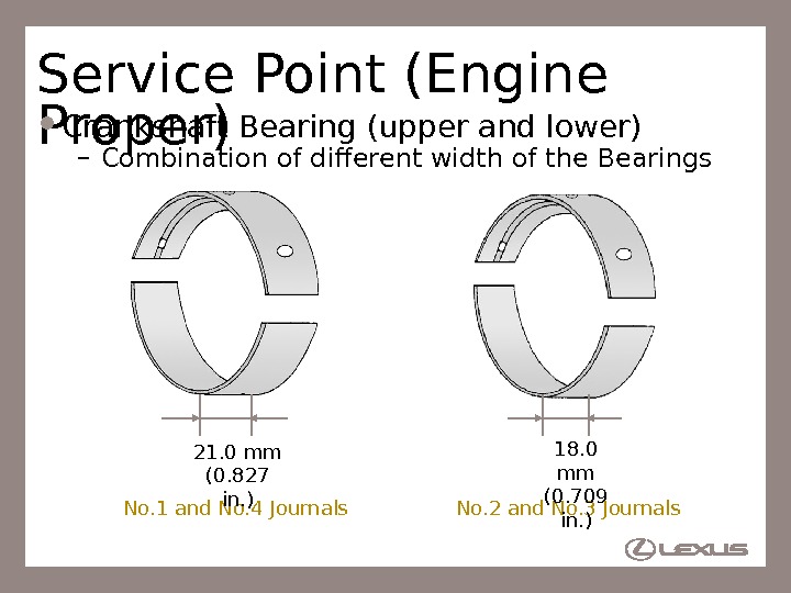
15 Service Point (Engine Proper) Crankshaft Bearing (upper and lower) – Combination of different width of the Bearings No. 1 and No. 4 Journals No. 2 and No. 3 Journals 18. 0 mm (0. 709 in. )21. 0 mm (0. 827 in. )
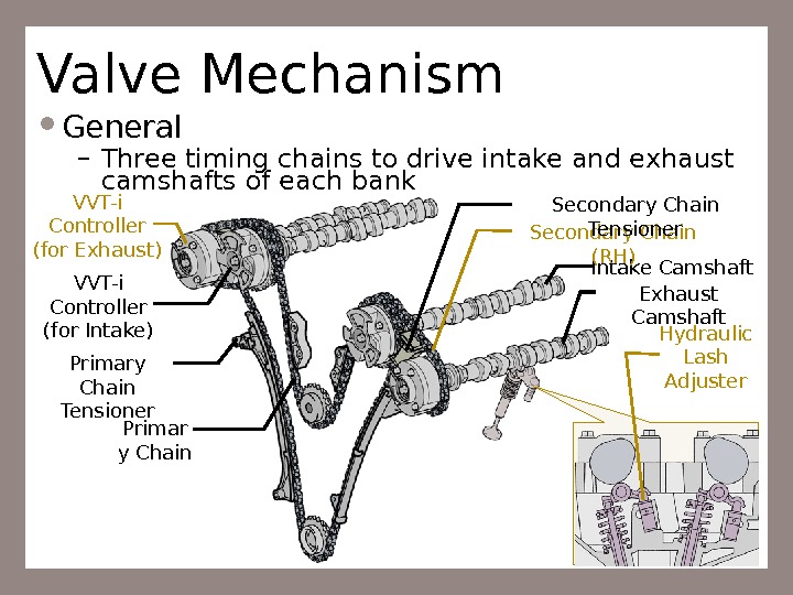
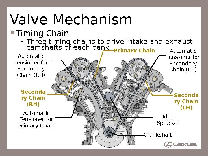
16 Valve Mechanism General – Three timing chains to drive intake and exhaust camshafts of each bank Intake Camshaft Exhaust Camshaft Primar y Chain. VVT-i Controller (for Exhaust) Secondary Chain (RH) Primary Chain Tensioner Secondary Chain Tensioner Hydraulic Lash Adjuster. VVT-i Controller (for Intake)
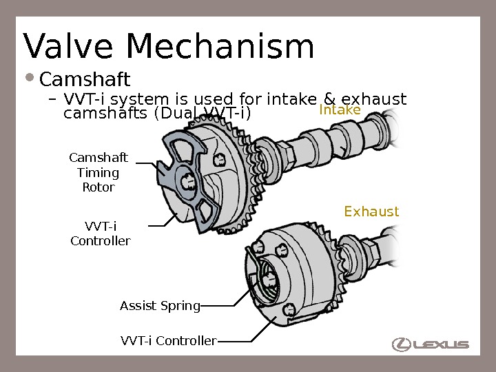
17 Valve Mechanism Camshaft – VVT-i system is used for intake & exhaust camshafts (Dual VVT-i) VVT-i Controller Intake Exhaust Assist Spring. Camshaft Timing Rotor
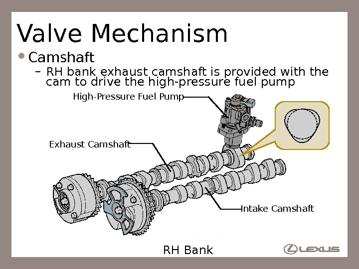
18 Valve Mechanism Camshaft – RH bank exhaust camshaft is provided with the cam to drive the high-pressure fuel pump RH Bank Intake Camshaft. Exhaust Camshaft High-Pressure Fuel Pump
19 Valve Mechanism Timing Chain – Three timing chains to drive intake and exhaust camshafts of each bank Crankshaft Idler Sprocket. Automatic Tensioner for Secondary Chain (RH) Automatic Tensioner for Secondary Chain (LH) Automatic Tensioner for Primary Chain Seconda ry Chain (RH) Seconda ry Chain (LH)
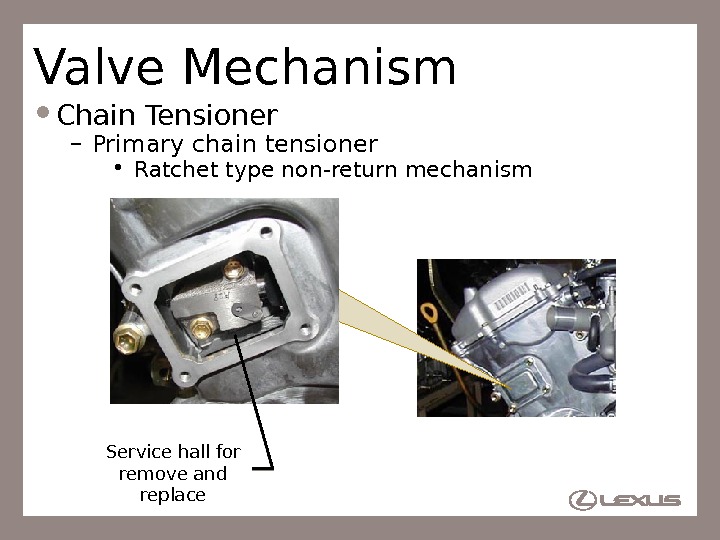
20 Valve Mechanism Chain Tensioner – Primary chain tensioner • Ratchet type non-return mechanism Service hall for remove and replace
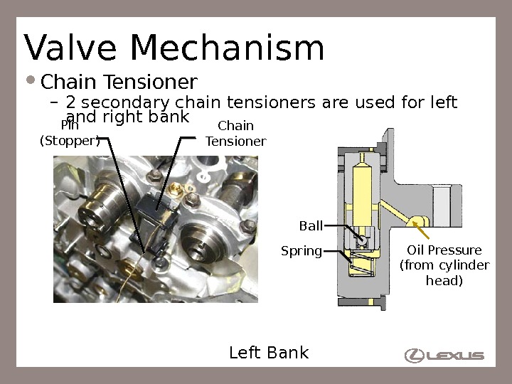
21 Valve Mechanism Chain Tensioner – 2 secondary chain tensioners are used for left and right bank Left Bank Spring Ball Oil Pressure (from cylinder head)Pin (Stopper) Chain Tensioner
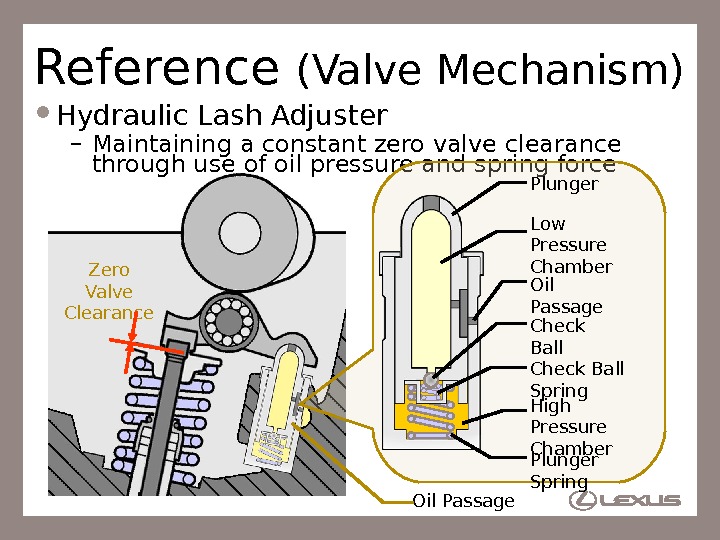
22 Zero Valve Clearance. Reference (Valve Mechanism) Hydraulic Lash Adjuster – Maintaining a constant zero valve clearance through use of oil pressure and spring force Oil Passage Plunger Oil Passage Check Ball Spring. Check Ball Plunger Spring. Low Pressure Chamber High Pressure Chamber
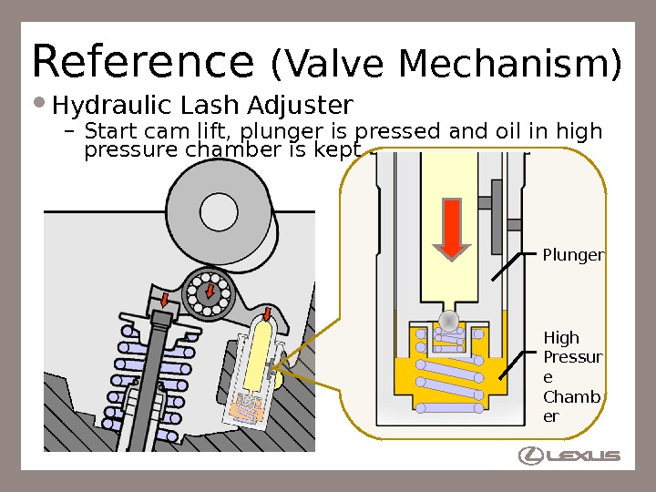
23 Reference (Valve Mechanism) Hydraulic Lash Adjuster – Start cam lift, plunger is pressed and oil in high pressure chamber is kept High Pressur e Chamb er. Plunger
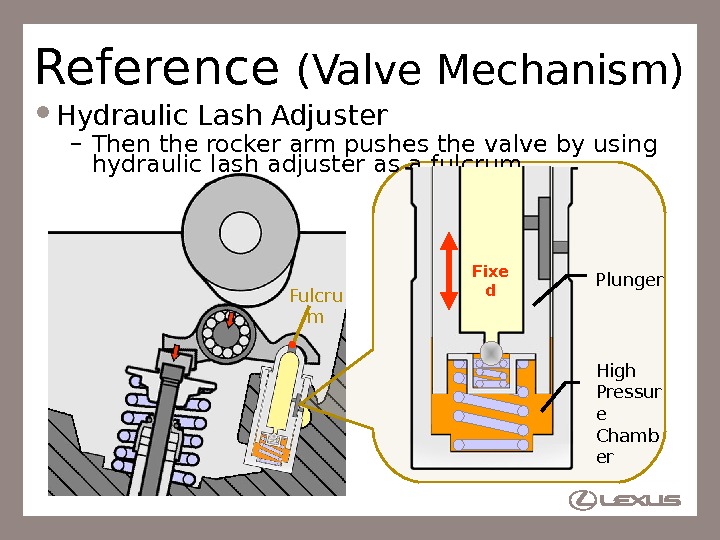
24 Fulcru m. Reference (Valve Mechanism) Hydraulic Lash Adjuster – Then the rocker arm pushes the valve by using hydraulic lash adjuster as a fulcrum Fixe d High Pressur e Chamb er. Plunger
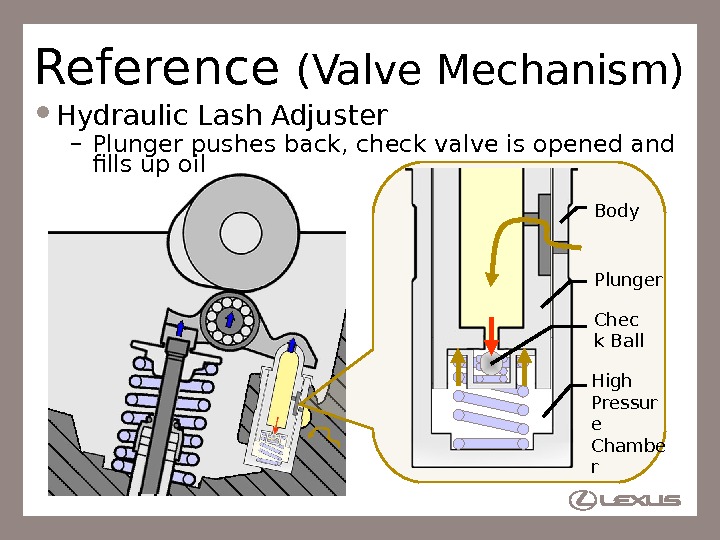
25 Reference (Valve Mechanism) Hydraulic Lash Adjuster – Plunger pushes back, check valve is opened and fills up oil High Pressur e Chambe r Body Chec k Ball. Plunger
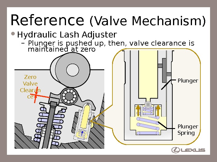
26 Zero Valve Clearan ce. Reference (Valve Mechanism) Hydraulic Lash Adjuster – Plunger is pushed up, then, valve clearance is maintained at zero Plunger Spring Plunger
27 Reference (Valve Mechanism) Hydraulic Lash Adjuster – Operation
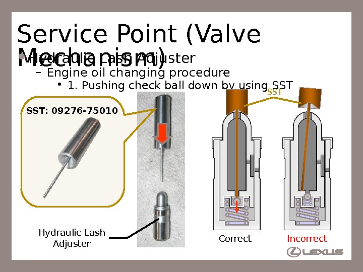
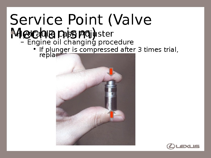
28 Service Point (Valve Mechanism) Hydraulic Lash Adjuster – Engine oil changing procedure • 1. Pushing check ball down by using SST Hydraulic Lash Adjuster. SST: 09276 -75010 Correct Incorrect. SST
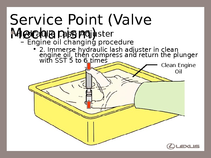
29 Service Point (Valve Mechanism) Hydraulic Lash Adjuster – Engine oil changing procedure • 2. Immerse hydraulic lash adjuster in clean engine oil, then compress and return the plunger with SST 5 to 6 times Clean Engine Oil
30 Service Point (Valve Mechanism) Hydraulic Lash Adjuster – Engine oil changing procedure • 3. Press the plunger by finger and check the blockage of plunger
31 Service Point (Valve Mechanism) Hydraulic Lash Adjuster – Engine oil changing procedure • If plunger is compressed after 3 times trial, replace to new one
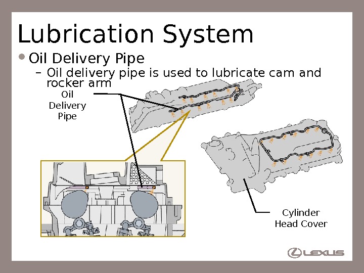
32 Lubrication System Oil Delivery Pipe – Oil delivery pipe is used to lubricate cam and rocker arm Oil Delivery Pipe Cylinder Head Cover
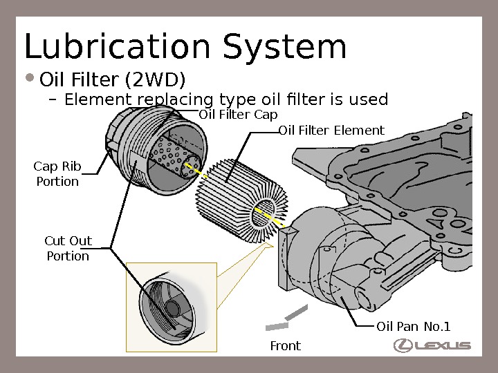
33 Lubrication System Oil Filter (2 WD) – Element replacing type oil filter is used Oil Filter Cap Oil Filter Element Oil Pan No. 1 Cut Out Portion Front. Cap Rib Portion
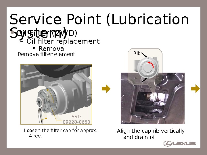
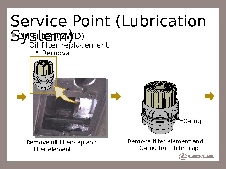
34 Service Point (Lubrication System) Oil Filter (2 WD) – Oil filter replacement • Removal Loosen the filter cap for approx. 4 rev. Remove filter element SST: 09228 -0650 1 Align the cap rib vertically and drain oil Rib
35 Service Point (Lubrication System) Oil Filter (2 WD) – Oil filter replacement • Removal Remove oil filter cap and filter element Remove filter element and O-ring from filter cap O-ring
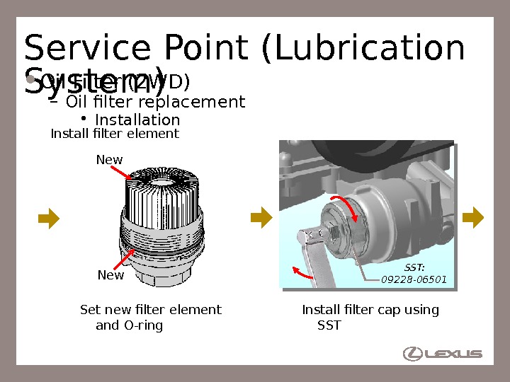
36 Service Point (Lubrication System) Oil Filter (2 WD) – Oil filter replacement • Installation Set new filter element and O-ring. New Install filter cap using SST: 09228 -06501 Install filter element
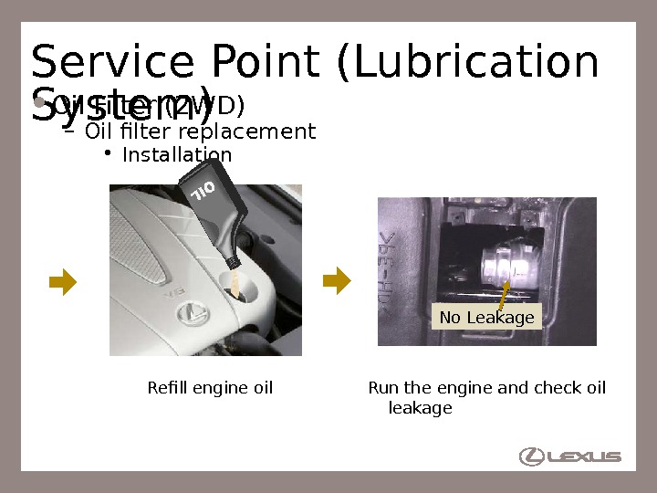
37 Service Point (Lubrication System) Oil Filter (2 WD) – Oil filter replacement • Installation Refill engine oil Run the engine and check oil leakage No Leakage
38 Intake and Exhaust System ACIS Valve – Rotary solenoid type ACIS valve is used – ACIS valve is unified by laser-welding Plasti c Laser-welding. Rotary Solenoid Type ACIS Valve
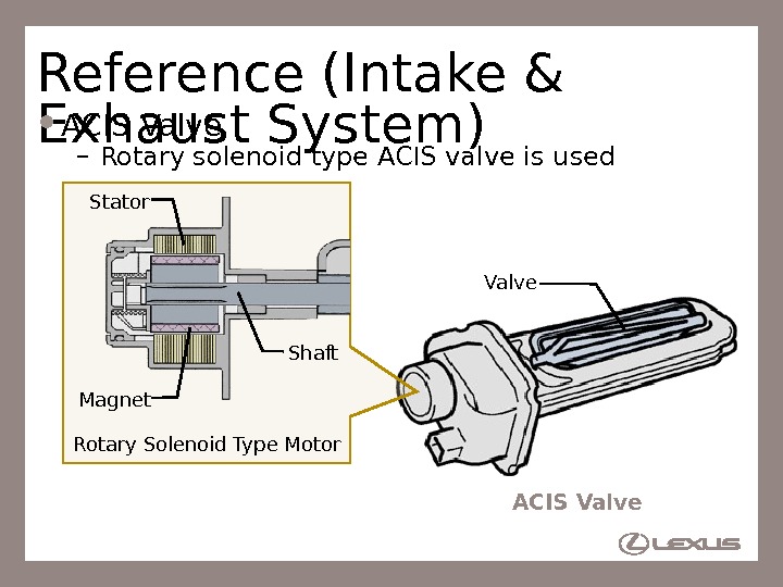
39 Reference (Intake & Exhaust System) ACIS Valve – Rotary solenoid type ACIS valve is used Valve Rotary Solenoid Type Motor Magnet Shaft. Stator ACIS Valve
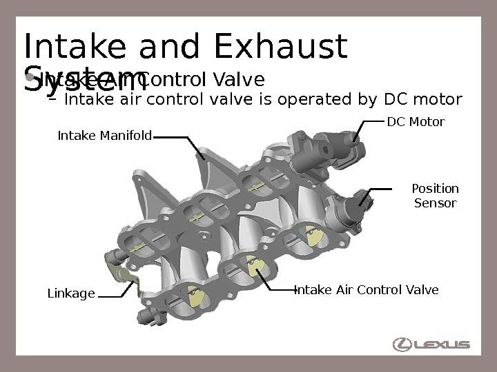
40 Intake and Exhaust System Intake Air Control Valve – Intake air control valve is operated by DC motor DC Motor Intake Air Control Valve. Intake Manifold Linkage Position Sensor
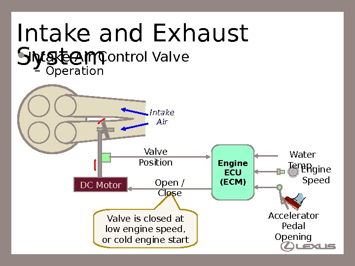
41 Valve is closed at low engine speed, or cold engine start. Intake and Exhaust System Intake Air Control Valve – Operation Intake Air DC Motor Accelerator Pedal Opening Engine Speed. Water Temp. Open / Close Engine ECU (ECM)Valve Position
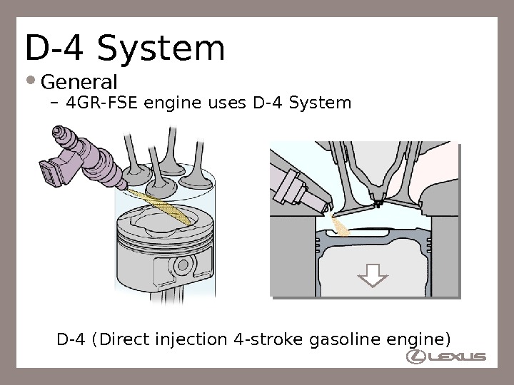
42 D-4 System General – 4 GR-FSE engine uses D-4 System D-4 (Direct injection 4 -stroke gasoline engine)
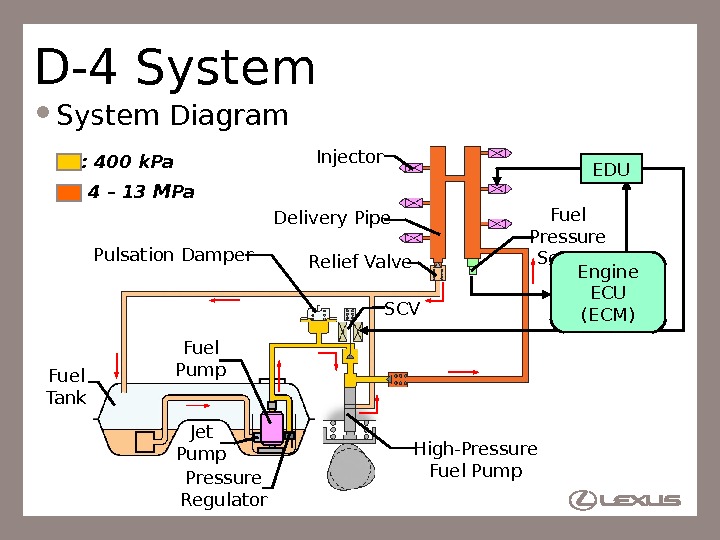
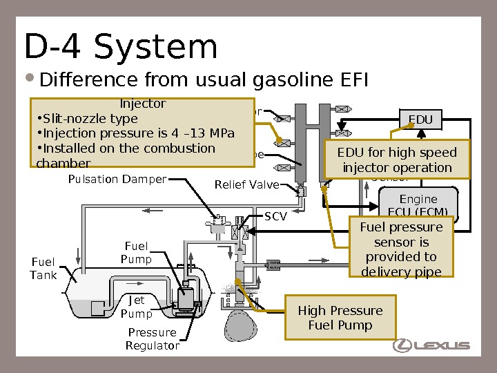
43 D-4 System Diagram High-Pressure Fuel Pump. Injector Fuel Pressure Sensor Fuel Tank Delivery Pipe Fuel Pump Pressure Regulator: 4 – 13 MPa : 400 k. Pa Pulsation Damper SCVRelief Valve Jet Pump Engine ECU (ECM) EDU
44 High-Pressure Fuel Pump I nj ector Fuel Pressure Sensor Fuel Tank Delivery Pipe Fuel Pump Pressure Regulator : 4 – 13 MPa : 400 k. Pa Pulsation Damper SCV Relief Valve J et Pump Engine ECU ( ECM) EDU D-4 System Difference from usual gasoline EFI Injector • Slit-nozzle type • Injection pressure is 4 – 13 MPa • Installed on the combustion chamber High Pressure Fuel Pump Fuel pressure sensor is provided to delivery pipe. EDU for high speed injector operation
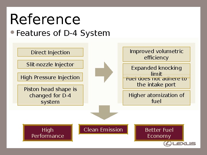
45 Reference Features of D-4 System Direct Injection High Pressure Injection Slit-nozzle Injector Fuel does not adhere to the intake port Higher atomization of fuel. Improved volumetric efficiency Expanded knocking limit Piston head shape is changed for D-4 system High Performance Clean Emission Better Fuel Economy
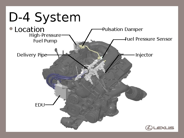
46 D-4 System Location High-Pressure Fuel Pump Injector. Fuel Pressure Sensor Delivery Pipe EDU Pulsation Damper
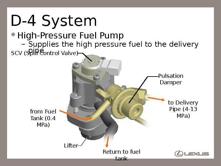
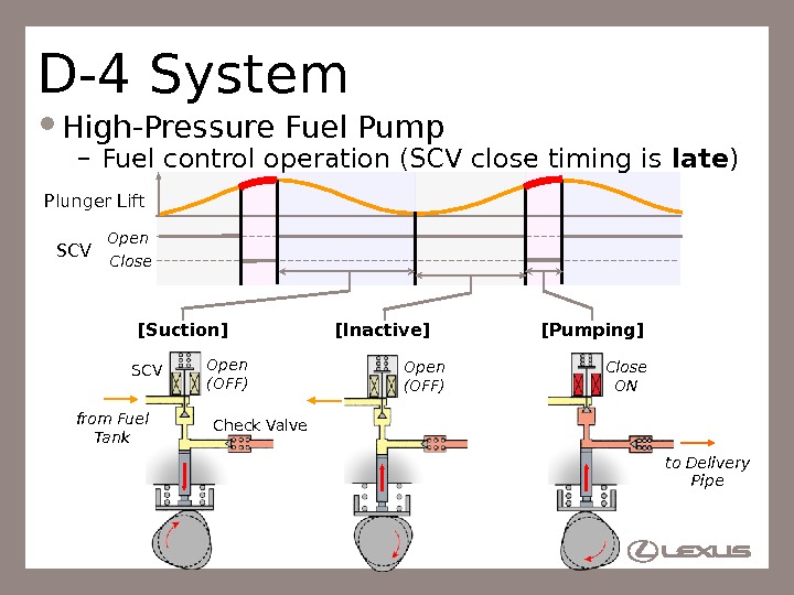
47 D-4 System High-Pressure Fuel Pump – Supplies the high pressure fuel to the delivery pipe SCV (Spill Control Valve) from Fuel Tank (0. 4 MPa) to Delivery Pipe (4 -13 MPa)Pulsation Damper Return to fuel tank. Lifter
48 D-4 System High-Pressure Fuel Pump – Fuel control operation (SCV close timing is late ) Plunger Lift SCV Open Close ONOpen (OFF)[Suction] [Inactive] Check Valve. SCV to Delivery Pipefrom Fuel Tank [Pumping]
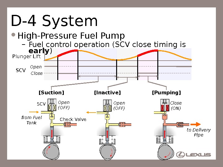
49 D-4 System High-Pressure Fuel Pump – Fuel control operation (SCV close timing is early ) Plunger Lift SCV Open Close (ON)Open (OFF)[Suction] [Inactive] [Pumping] Check Valve. SCV to Delivery Pipefrom Fuel Tank
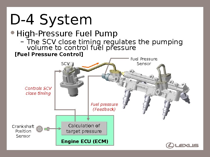
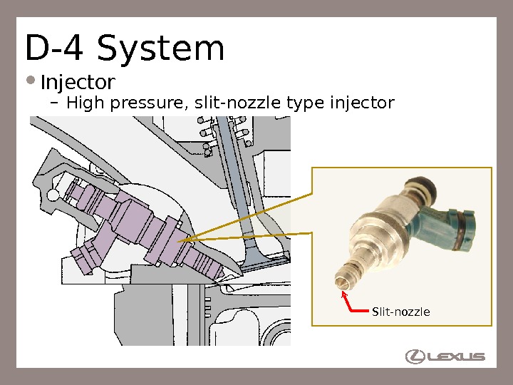
50 D-4 System High-Pressure Fuel Pump – The SCV close timing regulates the pumping volume to control fuel pressure Controls SCV close timing Fuel pressure (Feedback)SCV Fuel Pressure Sensor Crankshaft Position Sensor Engine ECU (ECM)[Fuel Pressure Control] Calculation of target pressure
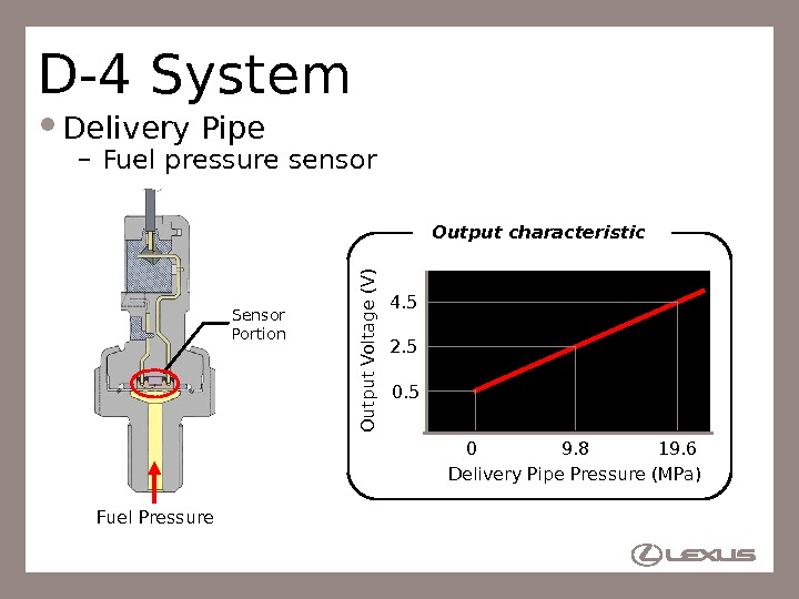
51 D-4 System Delivery Pipe – Stores high-pressure fuel (4 – 13 MPa) produced by high-pressure fuel pump Fuel Pressure Sensor Relief Valve. Delivery Pipe From Fuel Pump (High Pressure) Return to Fuel Tank Injector
52 D-4 System Delivery Pipe – Fuel pressure sensor Fuel Pressure 0 19. 60. 54. 5 Delivery Pipe Pressure (MPa)O u tpu t Voltag e (V )Output characteristic Sensor Portion 9. 82.
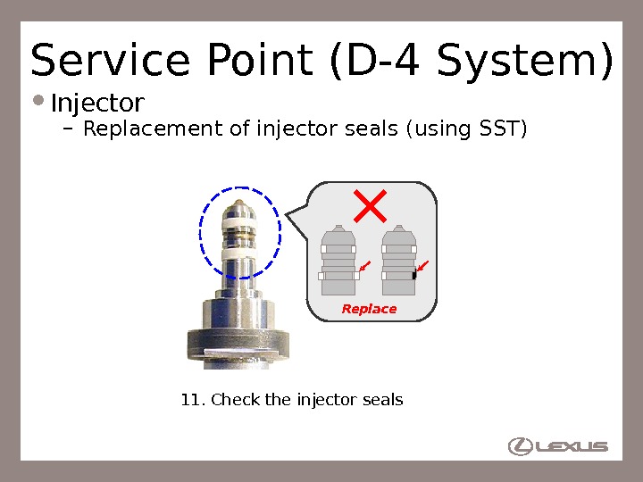
53 D-4 System Injector – High pressure, slit-nozzle type injector Slit-nozzle
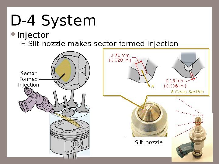
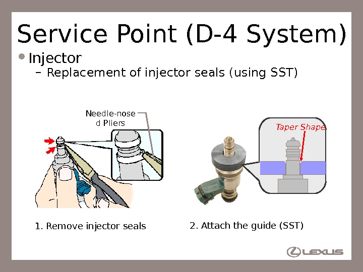
54 D-4 System Injector – Slit-nozzle makes sector formed injection Sector Formed Injection 0. 71 mm (0. 028 in. ) A 0. 15 mm (0. 006 in. ) A Cross Section Slit-nozzle
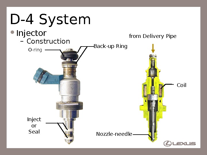
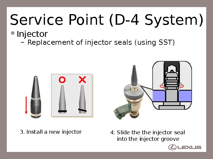
55 D-4 System Injector – Construction Inject or Seal Back-up Ring O-ring Nozzle-needle from Delivery Pipe Coil
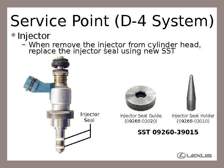
56 Service Point (D-4 System) Injector – When remove the injector from cylinder head, replace the injector seal using new SST Injector Seal Guide (09268 -03020) Injector Seal Holder (09268 -03010) SST 09260 —
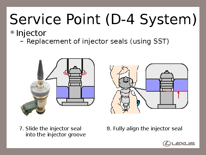
57 Service Point (D-4 System) Injector – Replacement of injector seals (using SST) Needle-nose d Pliers 1. Remove injector seals 2. Attach the guide (SST) Taper Shape
58 Service Point (D-4 System) Injector – Replacement of injector seals (using SST) 3. Install a new injector 4. Slide the injector seal into the injector groove
59 Service Point (D-4 System) Injector – Replacement of injector seals (using SST) 6. Install a new injector seal 5. Settle the injector seal Gentl y press
60 Service Point (D-4 System) Injector – Replacement of injector seals (using SST) 8. Fully align the injector seal 7. Slide the injector seal into the injector groove
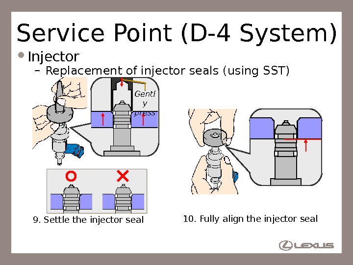
61 Service Point (D-4 System) Injector – Replacement of injector seals (using SST) 10. Fully align the injector seal 9. Settle the injector seal Gentl y press
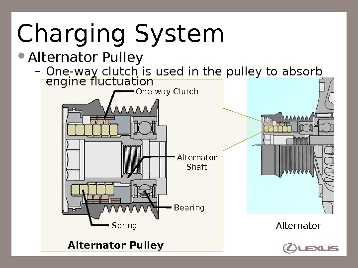
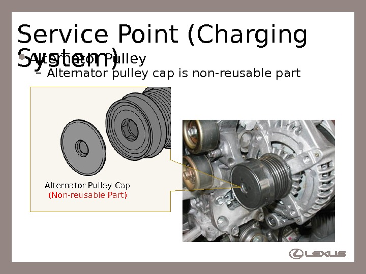
62 Service Point (D-4 System) Injector – Replacement of injector seals (using SST) 11. Check the injector seals Replace
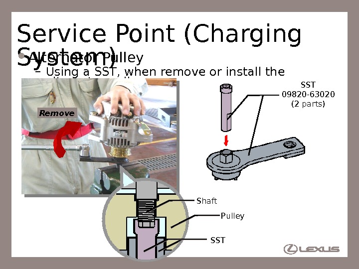
63 D-4 System EDU (Electronic Driver Unit) – Drives the injectors at high speed Engine ECU (ECM) EDU Injectors High Voltage DC / DC Converter Command Pulse Confirmation Pulse Battery IJT #1 -6 IJF Control Circuit High-speed operation
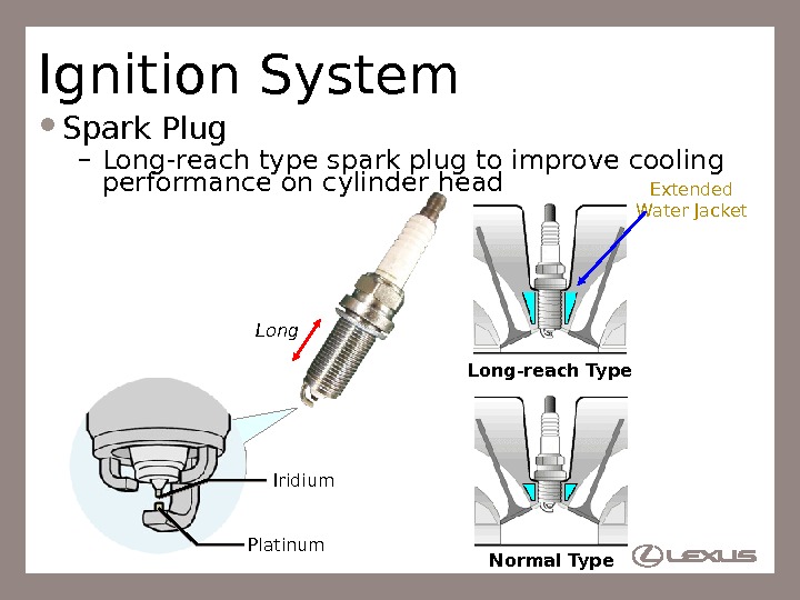
64 Ignition System Spark Plug – Long-reach type spark plug to improve cooling performance on cylinder head Extended Water Jacket Long-reach Type Normal Type. Long Iridium Platinum
65 Charging System Alternator Pulley – One-way clutch is used in the pulley to absorb engine fluctuation One-way Clutch Spring Bearing Alternator Shaft Alternator Pulley
66 Service Point (Charging System) Alternator Pulley – Using a SST, when remove or install the alternator pulley SST 09820 -63020 (2 parts) Remove SST Pulley. Shaft
67 Service Point (Charging System) Alternator Pulley – Alternator pulley cap is non-reusable part Alternator Pulley Cap (Non-reusable Part)
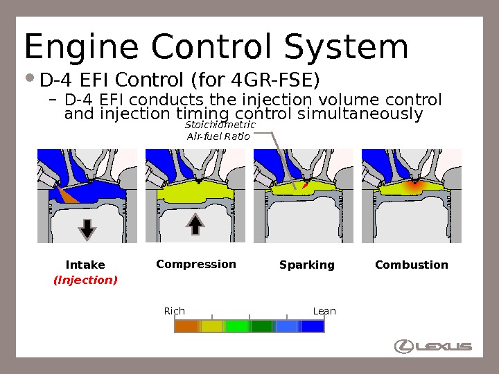
68 Engine Control System D-4 EFI Control (for 4 GR-FSE) – D-4 EFI conducts the injection volume control and injection timing control simultaneously Intake Compression Sparking Combustion Rich Lean. Stoichiometric Air-fuel Ratio (Injection)
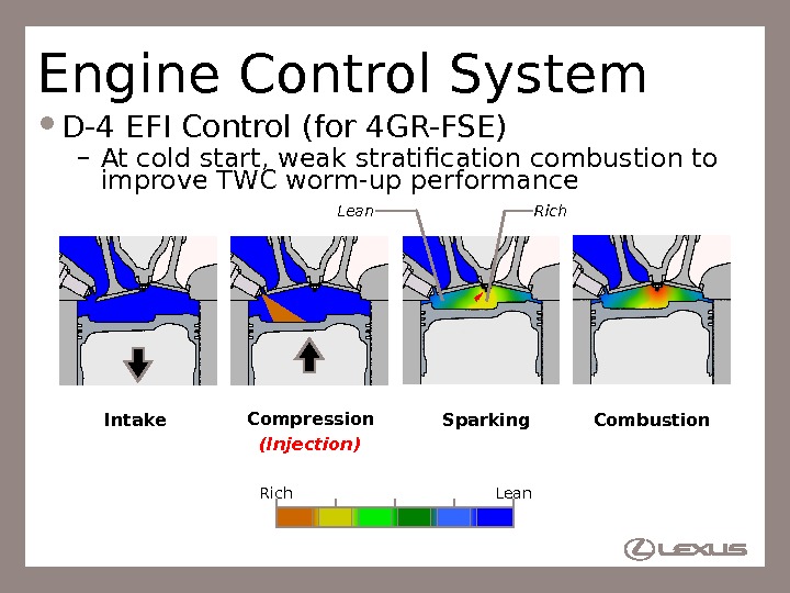
69 Engine Control System D-4 EFI Control (for 4 GR-FSE) – At cold start, weak stratification combustion to improve TWC worm-up performance Rich. Lean Intake Compression Sparking Combustion (Injection) Rich Lean
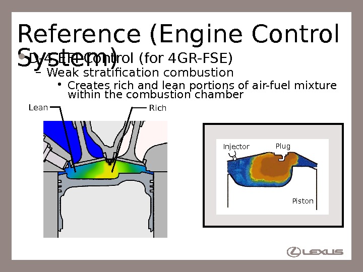
70 Reference (Engine Control System) D-4 EFI Control (for 4 GR-FSE) – Weak stratification combustion • Creates rich and lean portions of air-fuel mixture within the combustion chamber Injector Plug Piston. Rich. Lean Injector Plug Piston
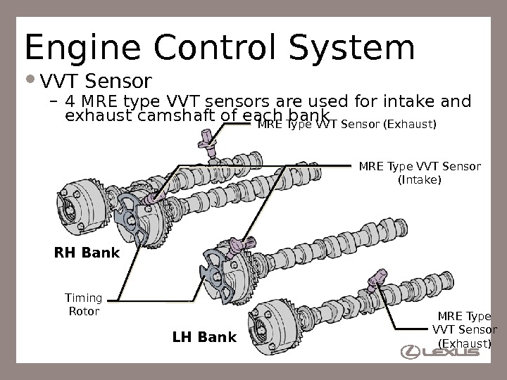
71 Engine Control System VVT Sensor – 4 MRE type VVT sensors are used for intake and exhaust camshaft of each bank Timing Rotor MRE Type VVT Sensor (Intake) LH Bank MRE Type VVT Sensor (Exhaust) RH Bank MRE Type VVT Sensor (Exhaust)
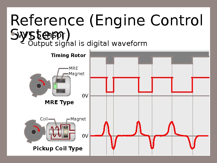
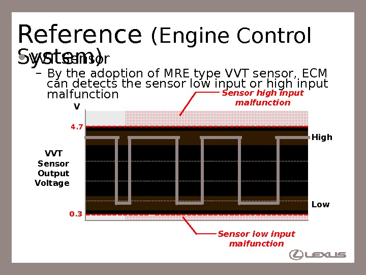
72 Reference (Engine Control System) VVT Sensor – Output signal is digital waveform MRE Type Pickup Coil Type 0 V 0 VMagnet MRE Coil Magnet. Timing Rotor
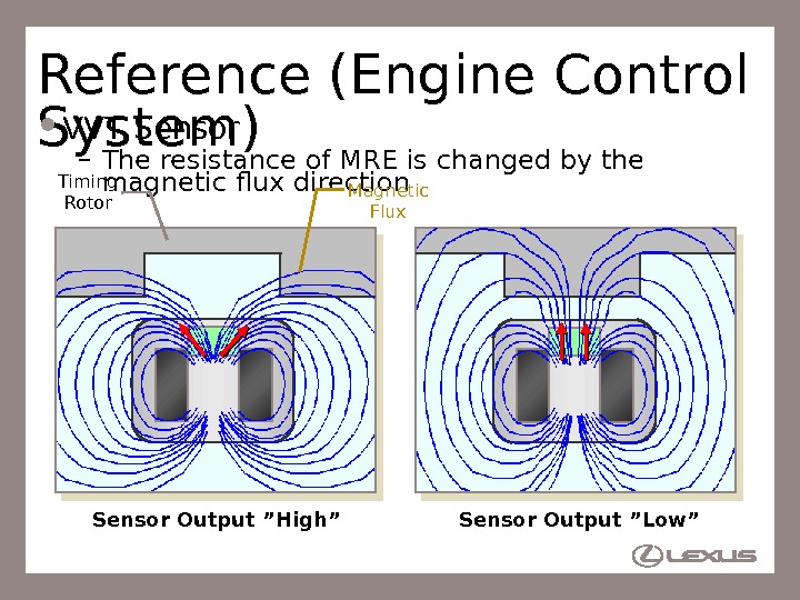
73 Reference (Engine Control System) VVT Sensor – The resistance of MRE is changed by the magnetic flux direction Sensor Output ”Low”Sensor Output ”High” Magnetic Flux. Timing Rotor
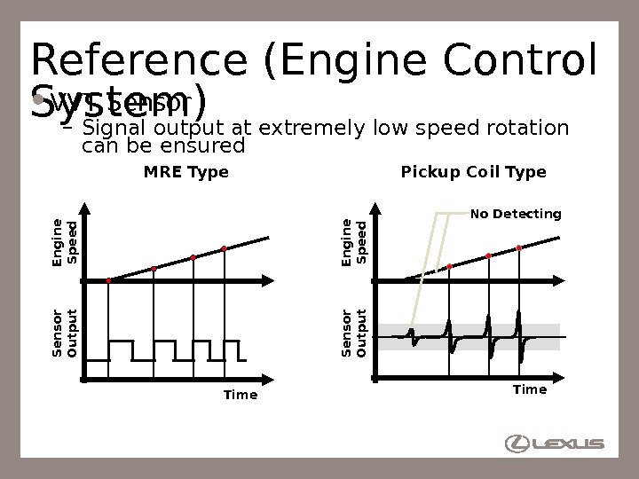
74 Reference (Engine Control System) VVT Sensor – Signal output at extremely low speed rotation can be ensured MRE Type Pickup Coil Type. S en sor O utp ut En g in e S p eed Time S en sor O utp ut En g in e S peed No Detecting Time
75 Reference (Engine Control System) VVT Sensor – By the adoption of MRE type VVT sensor, ECM can detects the sensor low input or high input malfunction V Sensor low input malfunction. VVT Sensor Output Voltage 0. 3 4. 7 Sensor high input malfunction High Low
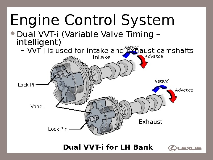
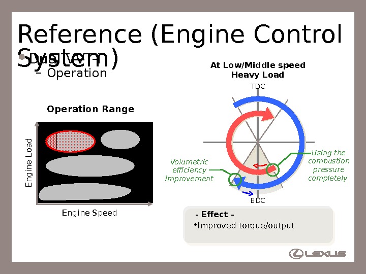
76 Engine Control System Dual VVT-i (Variable Valve Timing – intelligent) – VVT-i is used for intake and exhaust camshafts Intake Exhaust. Vane Lock Pin Advance. Retard Lock Pin Dual VVT-i for LH Bank
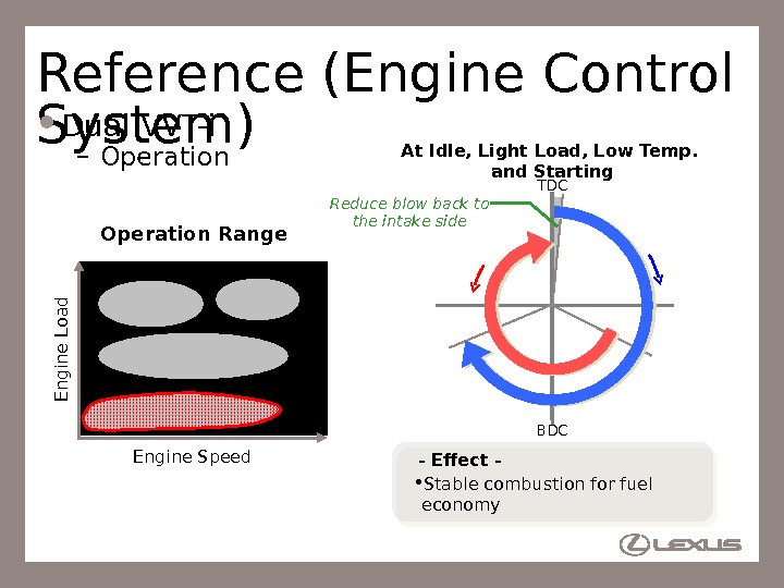
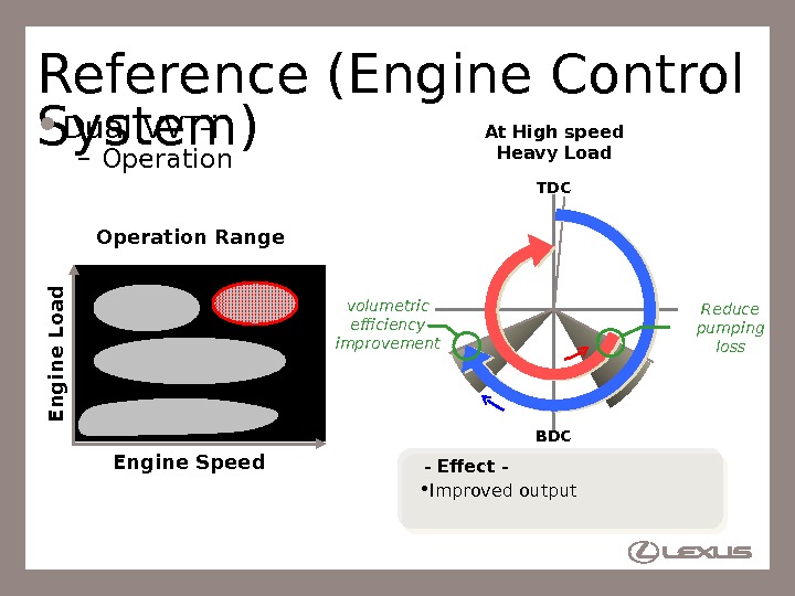
77 Reference (Engine Control System) Dual VVT-i – Operation — Effect — • Stable combustion for fuel economy. At Idle, Light Load, Low Temp. and Starting TDC BDCReduce blow back to the intake side. E ng in e Load Engine Speed. Operation Range
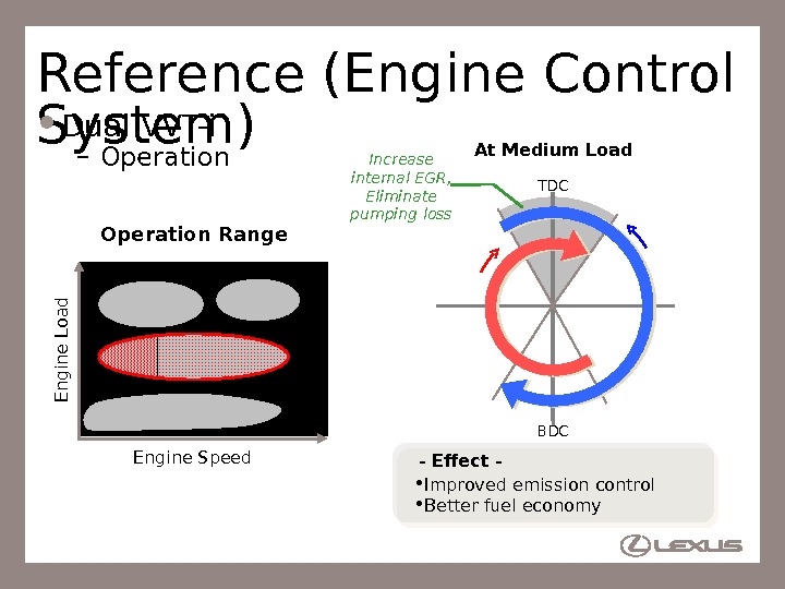
78 Reference (Engine Control System) Dual VVT-i – Operation — Effect — • Improved emission control • Better fuel economy At Medium Load TDC BDCIncrease internal EGR, Eliminate pumping loss. E ng in e Load Engine Speed. Operation Range
79 Reference (Engine Control System) Dual VVT-i – Operation — Effect — • Improved torque/output At Low/Middle speed Heavy Load TDC BDC Using the combustion pressure completely E ng in e Load Engine Speed. Operation Range Volumetric efficiency improvement
80 Reference (Engine Control System) Dual VVT-i – Operation. E n g in e L o a d Engine Speed At High speed Heavy Load Operation Range TDC BDCvolumetric efficiency improvement Reduce pumping loss — Effect — • Improved output
81 Service Point (Engine Control System) Dual VVT-i – Following 14 DTCs are added by adoption of exhaust VVT-i. DTC No. Detection Item P 001 3 Camshaft Position «B» Actuator Circuit (Bank 1) P 002 5 Camshaft Position «B» — Timing Over-Retarded (Bank 2) P 001 4 Camshaft Position «B» — Timing Over-Advanced or System Performance (Bank 1) P 036 5 Camshaft Position Sensor «B» Circuit (Bank 1) P 001 5 Camshaft Position «B» — Timing Over-Retarded (Bank 1) P 036 7 Camshaft Position Sensor «B» Circuit Low Input (Bank 1) P 001 7 Crankshaft Position — Camshaft Position Correlation (Bank 1 Sensor B) P 036 8 Camshaft Position Sensor «B» Circuit High Input (Bank 1) P 001 9 Crankshaft Position — Camshaft Position Correlation (Bank 2 Sensor B) P 039 0 Camshaft Position Sensor «B» Circuit (Bank 2) P 002 3 Camshaft Position «B» Actuator Circuit (Bank 2) P 039 2 Camshaft Position Sensor «B» Circuit Low Input (Bank 2) P 002 4 Camshaft Position «B» — Timing Over-Advanced or System Performance (Bank 2) P 039 3 Camshaft Position Sensor «B» Circuit High Input (Bank 2)
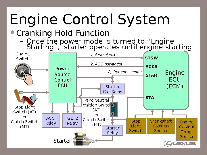
82 Engine Control System Cranking Hold Function – Once the power mode is turned to “Engine Starting”, starter operates until engine starting Starter Stop Light Switch (AT) or Clutch Switch (MT) ACC Relay IG 1, 2 Relay. Engine Switch Park Neutral Position Switch (AT) or Clutch Switch (MT) STSW ACCR STA 1, Start signal 2, ACC power cut Engine ECU (ECM)Power Source Control ECU 3, Operates starter Engine Coolant Temp. Sensor. Crankshaft Position Sensor. Stop Light Switch. Starter Cut Relay Starter Relay
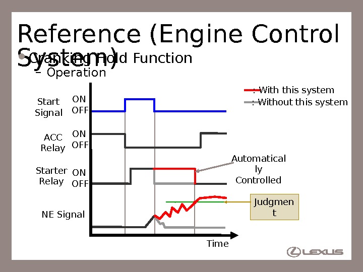
83 Reference (Engine Control System) Cranking Hold Function – Operation Start Signal Starter Relay ACC Relay NE Signal Time. ON : Without this system : With this system Automatical ly Controlled Judgmen t. OFF ON O
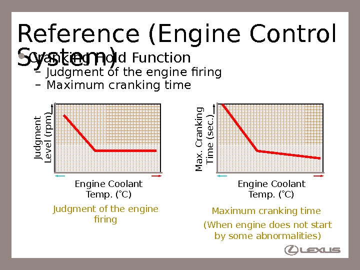
84 Reference (Engine Control System) Cranking Hold Function – Judgment of the engine firing – Maximum cranking time Engine Coolant Temp. ( C)Ju d g m e n t Le v e l (rp m ) Engine Coolant Temp. ( C) M a x. C ra n k in g T im e (se c. ) Judgment of the engine firing Maximum cranking time (When engine does not start by some abnormalities)
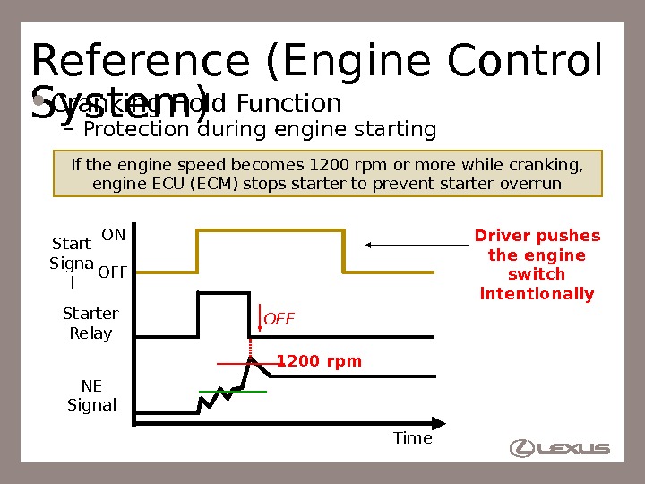
85 Reference (Engine Control System) Cranking Hold Function – Protection during engine starting 1200 rpm. OFF NE Signal ON Start Signa l OFF Starter Relay Time Driver pushes the engine switch intentionally. If the engine speed becomes 1200 rpm or more while cranking, engine ECU (ECM) stops starter to prevent starter overrun
86 Reference (Engine Control System) Cranking Hold Function – Protection during engine starting Engine does not start (Problem)Starter Relay NE Signal ON Start Signa l OFF Time Driver pushes the engine switch intentionally 30 sec. OFFStarter overheating protection operates starter max. 30 sec. with intentional starter operation
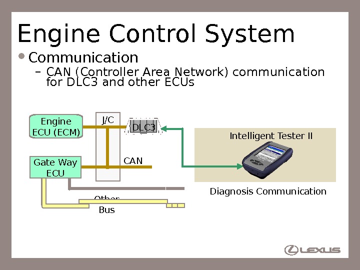
87 Engine Control System Communication – CAN (Controller Area Network) communication for DLC 3 and other ECUs J/C Engine ECU (ECM) DLC 3 CAN Other Bus Intelligent Tester II Gate Way ECU Diagnosis Communication