
1 © Nokia Siemens Networks Presentation /


- Размер: 3.5 Mегабайта
- Количество слайдов: 32
Описание презентации 1 © Nokia Siemens Networks Presentation / по слайдам
1 © Nokia Siemens Networks Presentation / Author / Date. For internal use Multivendor project Capability Management Ericsson 3 G site solutions April
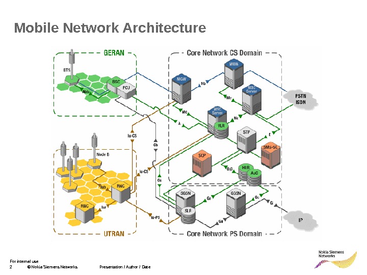
2 © Nokia Siemens Networks Presentation / Author / Date. For internal use Mobile Network Architecture
3 © Nokia Siemens Networks Presentation / Author / Date. For internal use Contents Chapter 1 Ericsson RNC Chapter 2 Ericsson Node. Bs
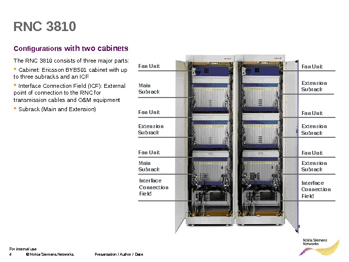
4 © Nokia Siemens Networks Presentation / Author / Date. For internal use Configurations with two cabinets. RNC 3810 Extension Subrack Fan Unit Interface Connection Field Fan Unit Extension Subrack Main Subrack Fan Unit Interface Connection Field. The RNC 3810 consists of three major parts: Cabinet: Ericsson BYB 501 cabinet with up to three subracks and an ICF Interface Connection Field (ICF): External point of connection to the RNC for transmission cables and O&M equipment Subrack (Main and Extension)
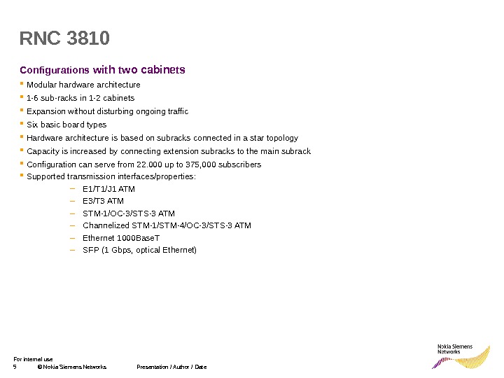
5 © Nokia Siemens Networks Presentation / Author / Date. For internal use Configurations with two cabinets Modular hardware architecture 1 -6 sub-racks in 1 -2 cabinets Expansion without disturbing ongoing traffic Six basic board types Hardware architecture is based on subracks connected in a star topology Capacity is increased by connecting extension subracks to the main subrack Configuration can serve from 22. 000 up to 375, 000 subscribers Supported transmission interfaces/properties: – E 1/T 1/J 1 ATM – E 3/T 3 ATM – STM-1/OC-3/STS-3 ATM – Channelized STM-1/STM-4/OC-3/STS-3 ATM – Ethernet 1000 Base. T – SFP (1 Gbps, optical Ethernet) RN
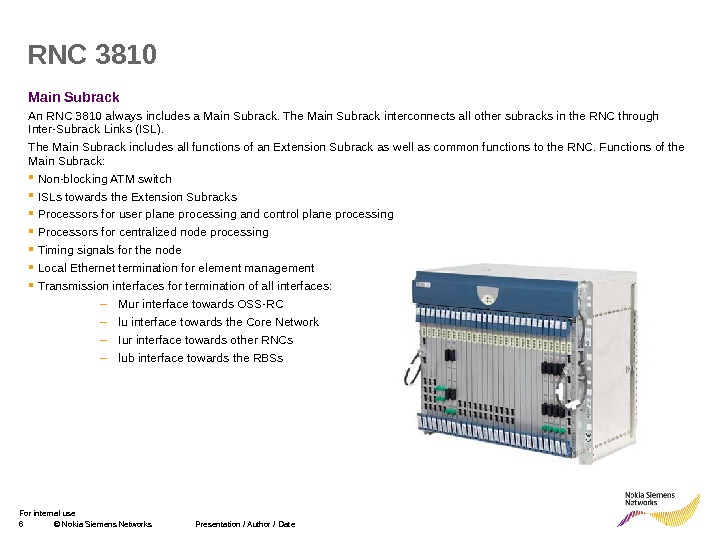
6 © Nokia Siemens Networks Presentation / Author / Date. For internal use Main Subrack An RNC 3810 always includes a Main Subrack. The Main Subrack interconnects all other subracks in the RNC through Inter-Subrack Links (ISL). The Main Subrack includes all functions of an Extension Subrack as well as common functions to the RNC. Functions of the Main Subrack: Non-blocking ATM switch ISLs towards the Extension Subracks Processors for user plane processing and control plane processing Processors for centralized node processing Timing signals for the node Local Ethernet termination for element management Transmission interfaces for termination of all interfaces: – Mur interface towards OSS-RC – lu interface towards the Core Network – Iur interface towards other RNCs – lub interface towards the RBSs. RN
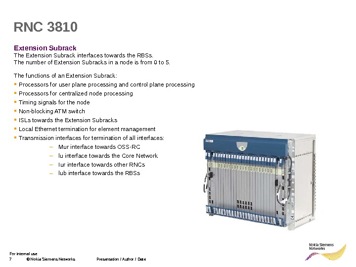
7 © Nokia Siemens Networks Presentation / Author / Date. For internal use Extension Subrack The Extension Subrack interfaces towards the RBSs. The number of Extension Subracks in a node is from 0 to 5. The functions of an Extension Subrack: Processors for user plane processing and control plane processing Processors for centralized node processing Timing signals for the node Non-blocking ATM switch ISLs towards the Extension Subracks Local Ethernet termination for element management Transmission interfaces for termination of all interfaces: – Mur interface towards OSS-RC – lu interface towards the Core Network – Iur interface towards other RNCs – lub interface towards the RBSs. RN
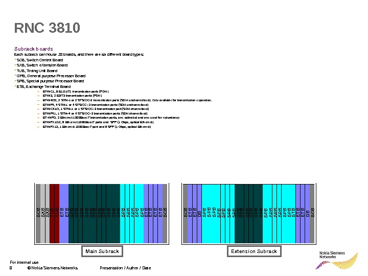
8 © Nokia Siemens Networks Presentation / Author / Date. For internal use Subrack boards Each subrack can house 28 boards, and there are six different board types: SCB, Switch Control Board SXB, Switch e. Xtension Board TUB, Timing Unit Board GPB, General purpose Processor Board SPB, Special purpose Processor Board ETB, Exchange Terminal Board – ET-MC 1 , 8 E 1/J 1/T 1 transmission ports (PDH) – ET-M 3 , 2 E 3/T 3 transmission ports (PDH) – ET-M 4/22 , 2 STM-1 or 2 STS/OC-3 transmission ports (SDH unchannelized). Only available for transmission expansion. – ET-MF 4 , 4 STM-1 or 4 STS/OC– 3 transmission ports (SDH unchannelized) – ET-MC 41/2 , 1 STM– 1 or 1 STS/OC– 3 transmission port (SDH channelized) – ET-MF 41 , 1 STM– 4 or 4 STS/OC– 3 transmission ports (SDH channelized) – ET–MFG , 2 Ethernet 1000 Base. T transmission ports, one activated and one used for redundancy – ET-MFX 12/2 , 6 Ethernet 1000 Base. T ports and SFP (1 Gbps, optical Ethernet) – ET-MFX 13 , 1 Ethernet 1000 Base. T port and 6 SFP (1 Gbps, optical Ethernet) RNC 3810 SCB SXB TUB ETB GPB GPB GPB SPB SPB SPB ETB ETB SCB ETB DBSPB SPB GPB GPB GPB SPB SPB SPB STB ETB DBSCB Main Subrack Extension Subrack
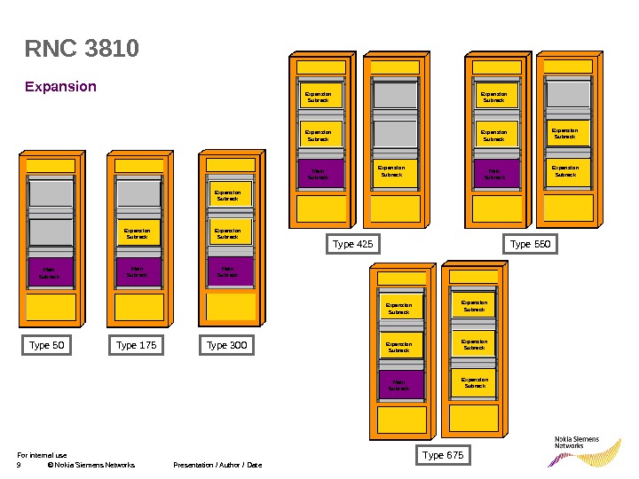
9 © Nokia Siemens Networks Presentation / Author / Date. For internal use Expansion. RNC 3810 Type 50 Type 175 Type 300 Type 425 Type 550 Type 675 Main Subrack. Expansion Subrack. Main Subrack. Expansion Subrack
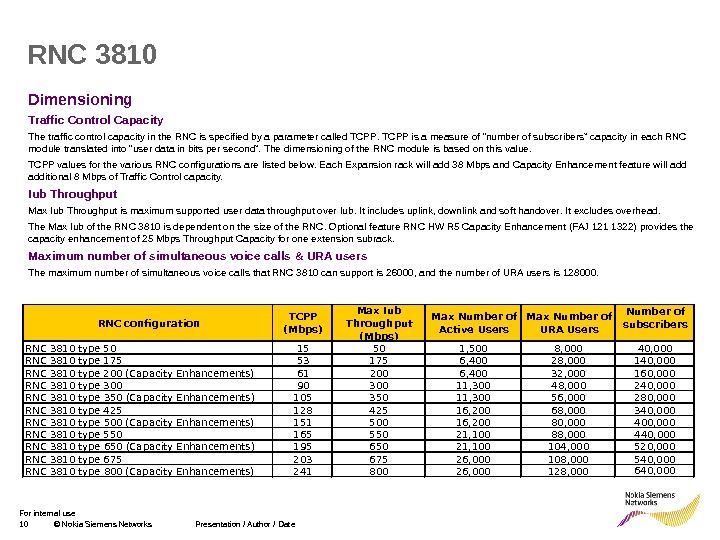
10 © Nokia Siemens Networks Presentation / Author / Date. For internal use Dimensioning Traffic Control Capacity The traffic control capacity in the RNC is specified by a parameter called TCPP is a measure of “ number of subscribers ” capacity in each RNC module translated into “ user data in bits per second ”. The dimensioning of the RNC module is based on this value. TCPP values for the various RNC configurations are listed below. Each Expansion rack will add 38 Mbps and Capacity Enhancement feature will additional 8 Mbps of Traffic Control capacity. Iub Throughput Max Iub Throughput is maximum supported user data throughput over Iub. It includ es uplink , downlink and soft handover. It exclud es overhead. The Max Iub of the RNC 3810 is dependent on the size of the RNC. Optional feature RNC HW R 5 Capacity Enhancement ( FAJ 121 1322 ) provides the capacity enhancement of 25 Mbps Throughput Capacity for one extension subrack. M aximum number of simultaneous voice calls & URA users The maximum number of simultaneous voice calls that RNC 3810 can support is 26000, and the number of URA users is 128000. RNC 3810 RNC configuration TCPP (Mbps) Max Iub Throughput (Mbps) Max Number of Active Users Max Number of URA Users Number of subscribers RNC 3810 type 50 15 50 1, 500 8, 000 40, 000 RNC 3810 type 175 53 175 6, 400 28, 000 140, 000 RNC 3810 type 200 (Capacity Enhancements) 61 200 6, 400 32, 000 160, 000 RNC 3810 type 300 90 300 11, 300 48, 000 240, 000 RNC 3810 type 350 (Capacity Enhancements) 105 350 11, 300 56, 000 280, 000 RNC 3810 type 425 128 425 16, 200 68, 000 340, 000 RNC 3810 type 500 (Capacity Enhancements) 151 500 16, 200 80, 000 400, 000 RNC 3810 type 550 165 550 21, 100 88, 000 440, 000 RNC 3810 type 650 (Capacity Enhancements) 195 650 21, 100 104, 000 520, 000 RNC 3810 type 675 203 675 26, 000 108, 000 540, 000 RNC 3810 type 800 (Capacity Enhancements) 241 800 26, 000 128, 000 640,
11 © Nokia Siemens Networks Presentation / Author / Date. For internal use Dimensioning Radio Network capability Up to 2304 cells and 768 RBSs Main subrack can handle 384 cells and 128 RBSs Extension subrack can handle 960 cells and 320 RBSs Maximum number of cell relations is 127 (63 WCDMA and 64 GSM) per cell Maximum number of cell relations is 82944 per RNC Maximum number of neighbour WCDMA cells is 2304 per RNC Maximum number of neighbour WCDMA cells is 7680 per RNC Maximum number of Location Areas is 47 per RNC Maximum number of Routing Areas is 154 per RNC Maximum number of Service Areas is 2304 per RNC Maximum number of active counters is 750000 per RNC Maximum number of all counters is 1200000 per RNCRN
12 © Nokia Siemens Networks Presentation / Author / Date. For internal use Contents Chapter 1 Ericsson RNC Chapter 2 Ericsson Node. Bs
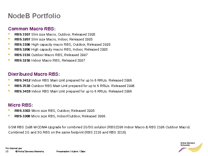
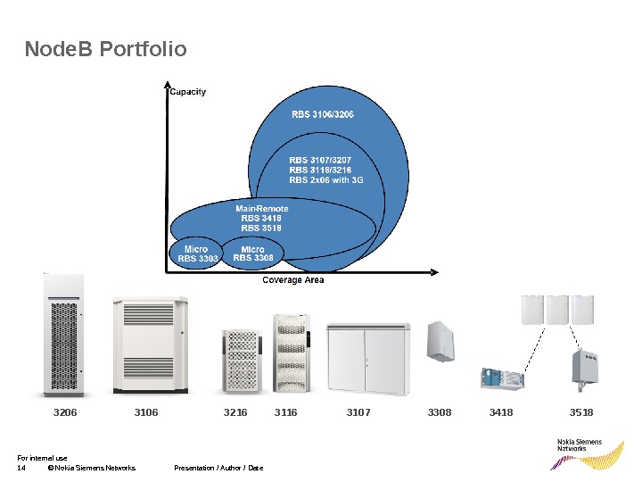
13 © Nokia Siemens Networks Presentation / Author / Date. For internal use Common Macro RBS: RBS 3107 Slim size Macro, Outdoor, Released 2005 RBS 3207 Slim size Macro, Indoor, Released 2005 RBS 3106 High capacity macro RBS, Outdoor, Released 2005 RBS 3206 High capacity macro RBS, Indoor, Released 2005 RBS 3116 Outdoor Macro RBS , Released 2007 RBS 3216 Indoor Macro RBS , Released 2007 Distributed Macro RBS: RBS 3412 In door RBS Main Unit prepared for up to 6 RRUs. Released 2006 RBS 3518 O utdoor RBS Main Unit prepared for up to 6 RRUs. Released 2006 RBS 3418 In door RBS Main Unit prepared for up to 6 RRUs. Released 2006 Micro RBS: RBS 3303 Micro size RBS, Outdoor, Released 2005 RBS 3308 Micro size RBS, Indoor/Outdoor, Released 2006 GSM RBS 2 x 06 WCDMA Upgrade for combined 2 G/3 G solution (RBS 2206 Indoor Macro & RBS 2106 Outdoor Macro) Combined 2 G and 3 G RBS on the same footprint (RBS 2216 and RBS 3216)Node. B Portfolio
14 © Nokia Siemens Networks Presentation / Author / Date. For internal use 3418 3518 3206 3107 3308 3216 3116 Node. B Portfolio
15 © Nokia Siemens Networks Presentation / Author / Date. For internal use RBS Licenses The purpose of license control is to control , with License Keys (LKs), capacity and optional functions of the RBS. A fter installing one or more corresponding LK s in the RBS , the operator can switched on and off optional features. Activation of LKs is with instalation of License Key File (LKF). LKF contai ns valid License Keys for the required features , capacities and node’s fingerprint. If no LKs are installed on the RBS, all licensed features are locked , all licensed capacities are limited to 0 , 8 CEs are available both for UL and DL. Administrative Correction for Licensing (FAJ 121 1006) Allows for the possibility to correct the licensed capacity level in case it has not initially been correctly set. It also allows for the correction of the functionality level. RBS Channel Elements Downlink ( FAJ 121 073 ) L imits the use of available Downlink Baseband hardware capacity to a level specified by the RBS LK. T he DL hardware in the RBS is limited to the DL licensed level specified by the LK. DL hardware in the RBS is TX board. A larm Uplink. Base. Band. Pool_Dl. Hw. Less. Than. Dl. Capacity is used to point i f the licensed capacity cannot be served. available. Rbs. Channel. Elements. Downlink shows the amount of DL channel elements. Range: {0. . 2147483647} ; Unit: 1 CE license. Capacity. Rbs. Channel. Elements. Downlink shows the licensed capacity limit of DL channel elements. Range: {0. . 2147483647} ; Unit: 1 CE license. State. Rbs. Channel. Elements. Downlink shows whether the licensed capacity of RBS channel elements for downlink R 99 traffic is enabled or disabled. RBS Channel Elements Uplink ( FAJ 121 072 ) L imits the use of available Uplink Baseband hardware capacity to a level specified by the RBS LK. T he U L hardware in the RBS is limited to the U L licensed level specified by the LK. UL hardware in the RBS is RAX board. A larm Uplink. Base. Band. Pool_ U l. Hw. Less. Than U l. Capacity is used to point i f the licensed capacity cannot be served. available. Rbs. Channel. Elements Up link shows the amount of UL channel elements available fo r R 99 traffic and EUL traffic. Range: {0. . 2147483647} ; Unit: 1 CE license. Capacity. Rbs. Channel. Elements Up link shows the licensed capacity limit of UL channel elements. Range: {0. . 2147483647} ; Unit: 1 CE license. State. Rbs. Channel. Elements Up link shows whether the licensed capacity of UL channel elements is enabled or disabled. Node. B Licenses
16 © Nokia Siemens Networks Presentation / Author / Date. For internal use Capacity Licenses Number of Carriers in RUW/RRUW based RBS ( FAJ 121 1344 ) This LK determines the number of carriers using RUW/RRUW that are allowed to be configured in an RB S. The re can be up to 12 carriers per RBS. T he number of carriers in the RBS must be lower or equal to the licensed level. Number of 40 W Power Amplifiers in RUW/RRUW based RBS ( FAJ 121 1347 ) This LK determines the number of 40 W power amplifiers in Main-Remote RBS , that are allowed to be configured. The re can be up to 12 power amplifiers with an output power of 4 0 W per RBS. T he number of power amplifiers configured to 40 W nominal output power in the RBS must be lower or equal to the licensed level. max. Total. Output. Power controls nominal output power of each RRU/RRUW. Each time a power amplifier is configured with a certain nominal output power the setting is compared with the licensed level. Tpa. Device_Number. Of 40 WPower. Amplifiers. Exceeds. Licensed. Limit alarm is issued i f the LK expires, is removed, or its value is decreased below the number of power amplifiers configured to operate at an output power of 40 W. Number of 60 W Power Amplifiers in RUW/RRUW based RBS ( FAJ 121 1348 ) This LK determines the number of 6 0 W power amplifiers in Main-Remote RBS , that are allowed to be configured. The re can be up to 12 power amplifiers with an output power of 60 W per RBS. T he number of power amplifiers configured to 6 0 W nominal output power in the RBS must be lower or equal to the licensed level. max. Total. Output. Power controls nominal output power of each RRU/RRUW. Each time a power amplifier is configured with a certain nominal output power the setting is compared with the licensed level. Tpa. Device_Number. Of 6 0 WPower. Amplifiers. Exceeds. Licensed. Limit alarm is issued i f the LK expires, is removed, or its value is decreased below the number of power amplifiers configured to operate at an output power of 6 0 W. Node. B Licenses
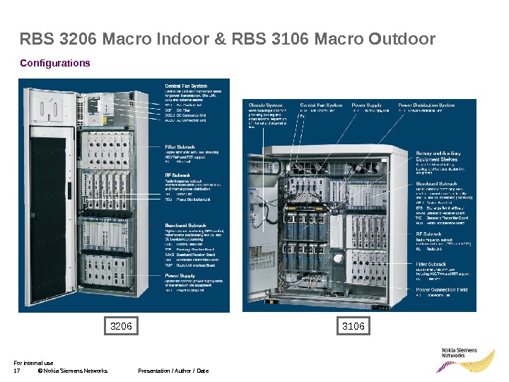
17 © Nokia Siemens Networks Presentation / Author / Date. For internal use RBS 3206 Macro Indoor & RBS 3106 Macro Outdoor Configurations
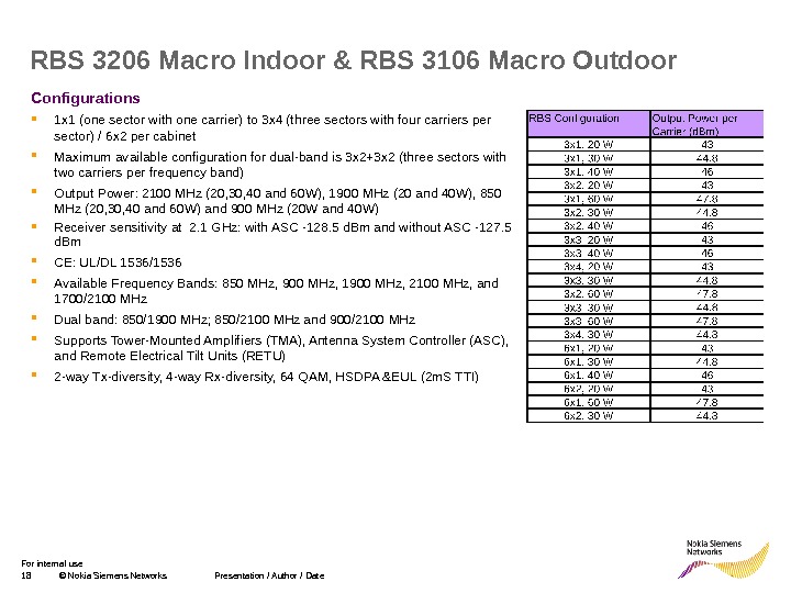
18 © Nokia Siemens Networks Presentation / Author / Date. For internal use Configurations 1 x 1 (one sector with one carrier) to 3 x 4 (three sectors with four carriers per sector) / 6 x 2 per cabinet Maximum available configuration for dual-band is 3 x 2+3 x 2 (three sectors with two carriers per frequency band) Output Power: 2100 MHz (20, 30, 40 and 60 W), 1900 MHz (20 and 40 W), 850 MHz (20, 30, 40 and 60 W) and 900 MHz (20 W and 40 W) Receiver sensitivity at 2. 1 GHz: with ASC -128. 5 d. Bm and without ASC -127. 5 d. Bm CE: UL/DL 1536/1536 Available Frequency Bands: 850 MHz, 900 MHz, 1900 MHz, 2100 MHz, and 1700/2100 MHz Dual band: 850/1900 MHz; 850/2100 MHz and 900/2100 MHz Supports Tower-Mounted Amplifiers (TMA), Antenna System Controller (ASC), and Remote Electrical Tilt Units (RETU) 2 -way Tx-diversity, 4 -way Rx-diversity, 64 QAM, HSDPA &EUL (2 m. S TTI)RBS 3206 Macro Indoor & RBS 3106 Macro Outdoor
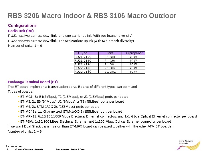
19 © Nokia Siemens Networks Presentation / Author / Date. For internal use Configurations Radio Unit (RU) RU 21 has two carriers downlink, and one carrier uplink (with two-branch diversity). RU 22 has two carriers downlink, and two carriers uplink (with two-branch diversity). Number of units: 1 – 9 RBS 3206 Macro Indoor & RBS 3106 Macro Outdoor Exchange Terminal Board (ET) The ET board implements transmission ports. B oards of different types can be mixe d. T ypes of boards: • ET-MC 1, 8 x E 1 (2 Mbps) , T 1 (1. 5 Mbps) , or J 1 (1. 5 Mbps) ports per board • ET-M 3, 2 x E 3 (34 Mbps), J 2 (6 Mbps) or T 3 (45 Mbps) ports per board • ET-M 4, 2 x STM-1 / OC-3 c (155 Mbps) ports per board • ET-MC 41 s, 1 x Channelized STM-1 / OC-3 (155 Mbps) port per board • ET-MFX 11 , 6 x 10/1000 Mbps Electrical Ethernet connectors and 1 x 1 G bps Optical Ethernet connector per board • ET-PSW, 1 x 10/100 Mbps Electrical Ethernet and 1 x 100 Mbps Optical Ethernet connector per board If we want Dual Stack transmission than ET-MFX board can be used together with the other ATM ET boards. Number of units: 1 –
20 © Nokia Siemens Networks Presentation / Author / Date. For internal use Configurations Random Access and Receiver Board (RAXB) The RAX board is used for uplink digital processing. A ll RAX boards in the RBS baseband pool are used for process ing of incoming data at the same time. RAX boards are available with differen t CE capacities. Extra capacity is added by license keys or by adding more boards up to maximum capacity. Two type of RAX boards: RAX R 2 with 32, 64 and 128 CE and RAX R 2 e with 128 CE. They support HSDPA, EUL and Extended Cell range. Board RAX R 2 e also supports EUL 2 m. S TTI. Number of units: 1 – 12 RBS 3206 Macro Indoor & RBS 3106 Macro Outdoor Transmitter Board (TXB) The TX board is used for downlink digital processing. TX boards are available with different CE capacities. Extra capacity is added by license keys or by adding more boards up to maximum capacity. Resources for SOHO and Compressed mode are included in all TXB types. There are 5 types of TXB: TX R 1/R 2 with 228 CE TX R 3 with 64, 128 and 256 CE; MBMS and Tx. D support HSTX-15 with 128 CE; max 64 HSDPA and 32 EUL users per cell; 15 HSDPA codes; MBMS, Tx. D, 2 x. MIMO and 64 QAM support HSTX-45 with 384 CE; max 64 HSDPA and 32 EUL users per cell; 45 HSDPA codes; MBMS, Tx. D, 2 x. MIMO and 64 QAM support HSTX-60 with 384 CE; max 64 HSDPA and 32 EUL users per cell; 60 HSDPA codes; MBMS, Tx. D, 2 x. MIMO and 64 QAM support Number of units: 1 –
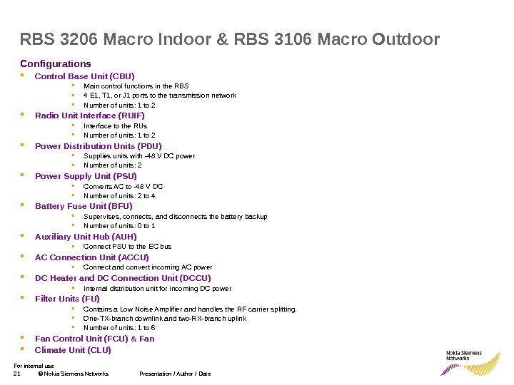
21 © Nokia Siemens Networks Presentation / Author / Date. For internal use Configurations Control Base Unit (CBU) Main c ontrol functions in the RBS 4 E 1, T 1, or J 1 ports to the transmission network Number of units: 1 to 2 Radio Unit Interface (RUIF) Interface to the RUs Number of units: 1 to 2 Power Distribution Units (PDU) S upplies units with -48 V DC power Number of units: 2 Power Supply Unit (PSU) C onverts AC t o -48 V DC Number of units: 2 to 4 Battery Fuse Unit (BFU) S upervises, connects, and disconnects the battery backup Number of units: 0 to 1 Auxiliary Unit Hub (AUH) C onnect PSU to the EC bus AC Connection Unit (ACCU) C onnect and convert incoming AC power DC Heater and DC Connection Unit (DCCU) I nternal distribution unit for incoming DC power Filter Units (FU) C ontains a Low Noise Amplifier and handles the RF carrier splitting. O ne-TX-branch downlink and two-RX-branch uplink Number of units: 1 to 6 Fan Control Unit (FCU) & Fan Climate Unit (CLU) RBS 3206 Macro Indoor & RBS 3106 Macro Outdoor
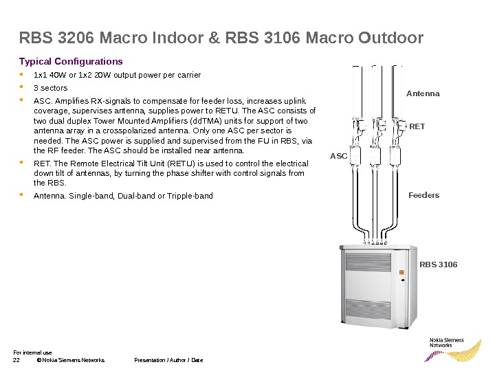
22 © Nokia Siemens Networks Presentation / Author / Date. For internal use Typical Configurations 1 x 1 40 W or 1 x 2 20 W output power per carrier 3 sectors ASC. Amplifies RX-signals to compensate for feeder loss, increases uplink coverage, supervises antenna, supplies power to RETU. The ASC consists of two dual duplex Tower Mounted Amplifiers (dd. TMA) units for support of two antenna array in a crosspolarized antenna. Only one ASC per sector is needed. The ASC power is supplied and supervised from the FU in RBS, via the RF feeder. The ASC should be installed near antenna. RET. The Remote Electrical Tilt Unit (RETU) is used to control the electrical down tilt of antennas, by turning the phase shifter with control signals from the RBS. Antenna. Single-band, Dual-band or Tripple-band. RBS 3206 Macro Indoor & RBS 3106 Macro Outdoor RET RBS 3106 Antenna ASC Feeders
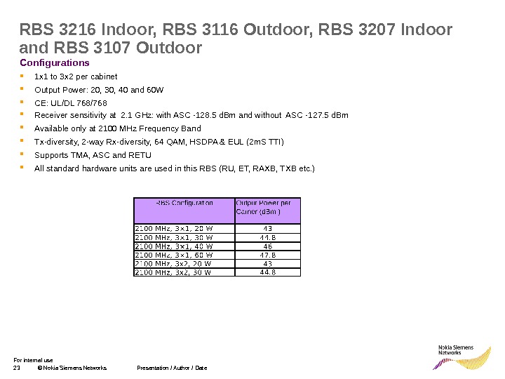
23 © Nokia Siemens Networks Presentation / Author / Date. For internal use Configurations 1 x 1 to 3 x 2 per cabinet Output Power: 20, 30, 40 and 60 W CE: UL/DL 768/768 Receiver sensitivity at 2. 1 GHz: with ASC -128. 5 d. Bm and without ASC -127. 5 d. Bm Available only at 2100 MHz Frequency Band Tx-diversity, 2 -way Rx-diversity, 64 QAM, HSDPA & EUL (2 m. S TTI) Supports T MA, ASC and RETU All standard hardware units are used in this RBS (RU, ET, RAXB, TXB etc. )RBS 3216 Indoor, RBS 3116 Outdoor, RBS 3207 Indoor and RBS 3107 Outdoor
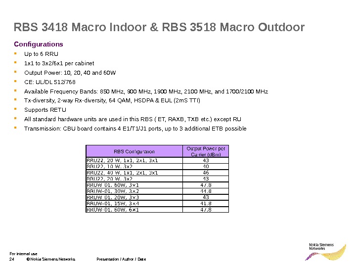
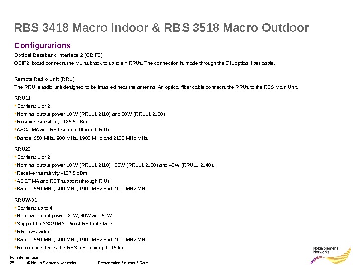
24 © Nokia Siemens Networks Presentation / Author / Date. For internal use Configurations Up to 6 RRU 1 x 1 to 3 x 2/6 x 1 per cabinet Output Power: 10, 20, 40 and 60 W CE: UL/DL 512/768 Available Frequency Bands: 850 MHz, 900 MHz, 1900 MHz, 2100 MHz, and 1700/2100 MHz Tx-diversity, 2 -way Rx-diversity, 64 QAM, HSDPA & EUL (2 m. S TTI) Supports RETU All standard hardware units are used in this RBS ( ET, RAXB, TXB etc. ) except RU Transmission : CBU board contains 4 E 1/T 1/J 1 ports , up to 3 additional ETB possible. RBS 3418 Macro Indoor & RBS 3518 Macro Outdoor
25 © Nokia Siemens Networks Presentation / Author / Date. For internal use Configurations Optical Baseband Interface 2 (OBIF 2) OBIF 2 board connects the MU subrack to up to six RRUs. The connection is made through the OIL optical fiber cable. Remote Radio Unit (RRU) The RRU is radio unit designed to be installed near the antenna. An optical fiber cable connects the RRUs to the RBS Main Unit. R R U 1 1 Carriers: 1 or 2 Nominal output power 10 W (RRU 11 2110) and 20 W (RRU 11 2120) Receiver sensitivity -126. 5 d. Bm ASC/TMA and RET support (through RIU) Bands: 850 MHz, 900 MHz, 1900 MHz and 2100 MHz R R U 2 2 Carriers: 1 or 2 Nominal output power 10 W (RRU 11 2110) , 20 W (RRU 11 2120) and 40 W (RRU 11 2140). Receiver sensitivity -127. 5 d. Bm ASC/TMA and RET support (through RIU) Bands: 850 MHz, 900 MHz, 1900 MHz and 2100 MHz RRUW-01 Carriers: up to 4 Nominal output power 20 W, 40 W and 60 W Support for ASC/TMA, Direct RET interface RRU cascading Bands: 850 MHz, 900 MHz, 1900 MHz and 2100 MHz R emotely extends the RBS reach by up to 15 km. RBS 3418 Macro Indoor & RBS 3518 Macro Outdoor
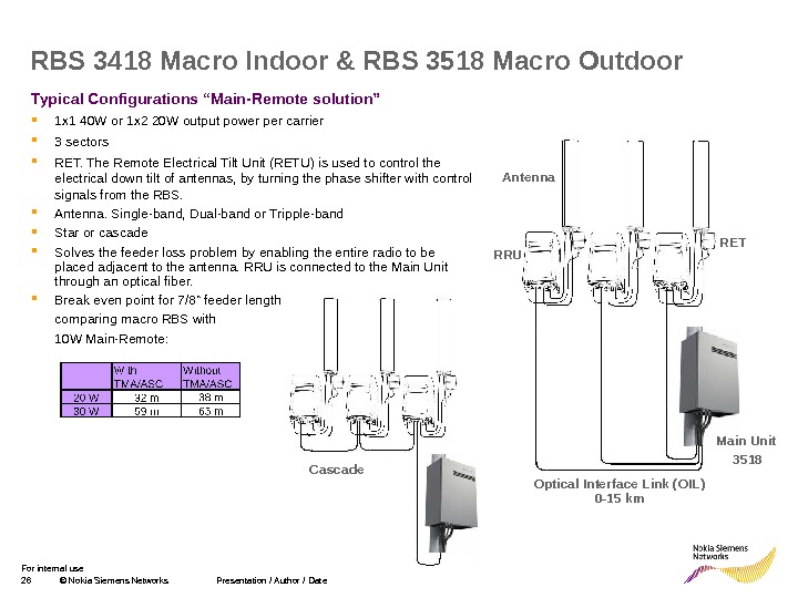
26 © Nokia Siemens Networks Presentation / Author / Date. For internal use Typical Configurations “Main-Remote solution” 1 x 1 40 W or 1 x 2 20 W output power per carrier 3 sectors RET. The Remote Electrical Tilt Unit (RETU) is used to control the electrical down tilt of antennas, by turning the phase shifter with control signals from the RBS. Antenna. Single-band, Dual-band or Tripple-band Star or cascade Solves the feeder loss problem by enabling the entire radio to be placed adjacent to the antenna. RRU is connected to the Main Unit through an optical fiber. Break even point for 7/8” feeder length comparing macro RBS with 10 W Main-Remote: RBS 3418 Macro Indoor & RBS 3518 Macro Outdoor Main Unit 3518 RRU Antenna RET Optical Interface Link (OIL) 0 -15 km. Cascade
27 © Nokia Siemens Networks Presentation / Author / Date. For internal use Configurations 1 x 1 configuration Output Power: 5 W and 20 W Receiver sensitivity: -126. 2 d. Bm with 2 -way Rx diversity without ASC CE: UL/DL 128/128 Available at 850 MHz, 1900 MHz and 2100 MHz Frequency Bands Tx-diversity, 2 -way Rx-diversity, 64 QAM, HSDPA & EUL (2 m. S TTI) Supports T MA, ASC and RETU RBS 3303 Micro Outdoor
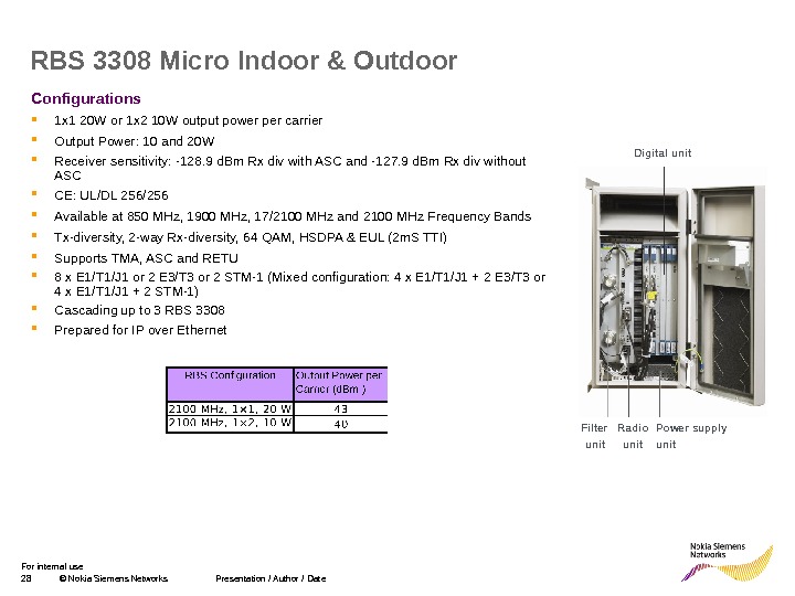
28 © Nokia Siemens Networks Presentation / Author / Date. For internal use Configurations 1 x 1 20 W or 1 x 2 10 W output power per carrier Output Power: 10 and 20 W Receiver sensitivity: -128. 9 d. Bm Rx div with ASC and -127. 9 d. Bm Rx div without ASC CE: UL/DL 256/256 Available at 850 MHz, 1900 MHz, 17/2100 MHz and 2100 MHz Frequency Bands Tx-diversity, 2 -way Rx-diversity, 64 QAM, HSDPA & EUL (2 m. S TTI) Supports T MA, ASC and RETU 8 x E 1/T 1/J 1 or 2 E 3/T 3 or 2 STM-1 (Mixed configuration: 4 x E 1/T 1/J 1 + 2 E 3/T 3 or 4 x E 1/T 1/J 1 + 2 STM-1) Cascading up to 3 RBS 3308 Prepared for IP over Ethernet. RBS 3308 Micro Indoor & Outdoor Power supply unit. Radio unit. Filter unit Digital unit
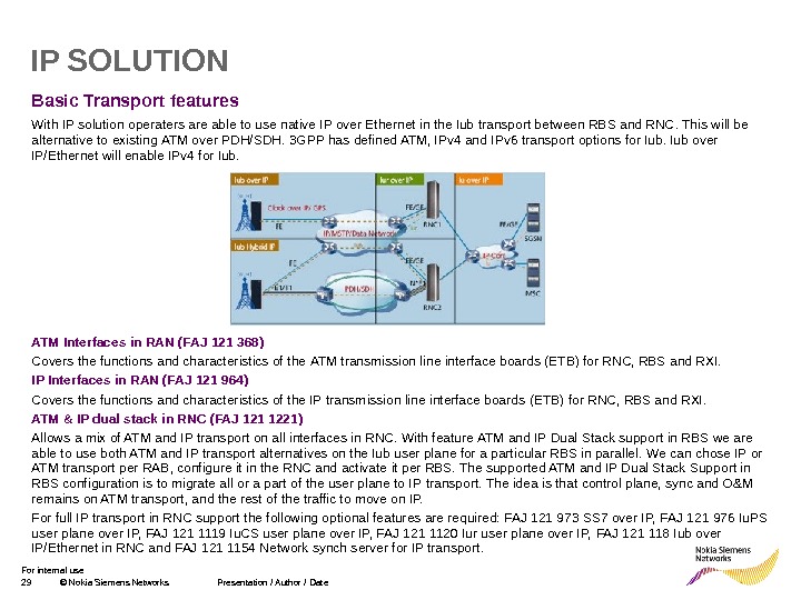
29 © Nokia Siemens Networks Presentation / Author / Date. For internal use Basic Transport features With IP solution operaters are able to use native IP over Ethernet in the Iub transport between RBS and RNC. This will be alternative to existing ATM over PDH/SDH. 3 GPP has defined ATM, IPv 4 and IPv 6 transport options for Iub over IP/Ethernet will enable IPv 4 for Iub. ATM Interfaces in RAN (FAJ 121 368) C overs the functions and characteristics of the ATM transmission line interface boards (ETB) for RNC, RBS and RXI. IP Interfaces in RAN (FAJ 121 964) C overs the functions and characteristics of the IP transmission line interface boards (ETB) for RNC, RBS and RXI. ATM & IP dual stack in RNC (FAJ 121 1221) Allows a mix of ATM and IP transport on all interfaces in RNC. With feature ATM and IP Dual Stack support in RBS we are able to use both ATM and IP transport alternatives on the Iub user plane for a particular RBS in parallel. We can chose IP or ATM transport per RAB , configure it in the RNC and activate it per RBS. T he supported ATM and IP Dual Stack Support in RBS configuration is to migrate all or a part of the user plane to IP transport. The idea is that control plane, sync and O&M remain s on ATM transport , and the rest of the traffic to move on IP. For full IP transport in RNC support t he following optional features are required: FAJ 121 973 SS 7 over IP, FAJ 121 976 Iu. PS user plane over IP, FAJ 121 1119 Iu. CS user plane over IP, FAJ 121 1120 Iur user plane over IP, FAJ 121 118 Iub over IP/Ethernet in RNC and FAJ 121 1154 Network synch server for IP transport. IP SOLUTION
30 © Nokia Siemens Networks Presentation / Author / Date. For internal use Optional Transport features SS 7 over IP (FAJ 121 973) P rovides the possibility to transport SS 7 signalling over IP. The required HW interfaces is Gigabit Ethernet Transmission board. Iur User Traffic over IP (FAJ 121 1120) E nables IP over Ethernet to be used for connecting the Iur user plane between two RNCs. The required HW interfaces is Gigabit Ethernet Transmission board. Iu. PS User Plane Traffic over IP (FAJ 121 976) E nables IP over Ethernet to be used for connecting the user plane between RNC and SGSN. The required HW interfaces is Gigabit Ethernet Transmission board. Iu. CS User Plane Traffic over IP (FAJ 121 1119) E nables IP over Ethernet to be used for connecting the user plane between RNC and MGW. This feature requires the optional RAN feature FAJ 121 964, IP interfaces in WCDMA RAN. Iub over IP/Ethernet in RNC (FAJ 121 1118) E nables the IP/Ethernet transport for Iub at the RNC. IP over Ethernet can also be used for subset of Iub connect ion of RBSes to RNC at the same time as ATM is used for another Iub connect ion sub-set. Iub Transport Split for Best Effort Data (FAJ 121 1101) M akes possible to use public IP transport services (eg x. DSL ) , for the WCDMA RAN Best Effort data traffic by allowing parallel TDM and Ethernet Iub transport links with different Qo. S characteristics to one and the same WCDMA RBS. T ransport split for best effort data on Iub is usually created with optional feature FAJ 121 1311, ATM and IP Dual Stack support in RBS. Iub over IP/Ethernet in RBS (FAJ 121 1132) At the RBS this feature enables the IP/Ethernet transport for Iub. The required HW interfaces is Multifunctional Ethernet Transmission Interface board. This feature requires the optional RAN features to be instaled: FAJ 121 964, IP interfaces in WCDMA RAN and FAJ 121 1118, Iub over IP transport in RNC. IP SOLUTION
31 © Nokia Siemens Networks Presentation / Author / Date. For internal use Optional Transport features Network Synch Server for IP transport (FAJ 121 1154) E nables network synchronization for RBS s only connected with IP. It provides the Synch Server part of the function in RNC or RXI. Feature Network Synch Client for IP transport should be implemented in the RBS. The required HW interfaces is Multifunctional Ethernet Transmission Interface board. This feature requires the optional RAN features to be instaled: FAJ 121 1132 Iub over IP transport in RBS , FAJ 121 1118, Iub over IP transport in RNC and FAJ 121 1155 Network Synch Client for IP transport (FAJ 121 1155) E nables network synchronization for RBS s only connected with IP. It provides the Synch Server part of the function in RNC or RXI. Feature Network Synch Server for IP transport should be implemented in the RBS. The required HW interfaces is Multifunctional Ethernet Transmission Interface board. This feature requires the optional RAN features to be instaled: FAJ 121 1132 Iub over IP transport in RBS , FAJ 121 1118, Iub over IP transport in RNC and FAJ 121 1154 Network Synch Server for IP transport. Iub over IP/Ethernet using Pseudo Wire (FAJ 121 1167) E 1/T 1 s can be converted to IP/Ethernet and be connected over a packet based network with Ethernet interface. This is possible with introduction of Ethernet Pseudo Wire Interface Board in RBS or a stand alone remote pseudo wire box and a P seudo W ire A ggregation G ateway node on the RNC side. ATM & IP dual stack in RBS (FAJ 121 1311) With implementing t his feature we are able to have a mix of ATM and IP transport for Iub in an RBS. It makes it possible to use IP transport with lower quality than when using Iub over native IP only. This feature requires the optional RAN features to be instaled: FAJ 121 1132 Iub over IP transport in RBS and FAJ 121 1221 Iub over IP/Ethernet in RNC. IP SOLUTION
32 © Nokia Siemens Networks Presentation / Author / Date. For internal use THANK YOU