
1 Descriptive geometry Introduction Descriptive geometry is one


- Размер: 3.5 Mегабайта
- Количество слайдов: 60
Описание презентации 1 Descriptive geometry Introduction Descriptive geometry is one по слайдам
1 Descriptive geometry Introduction Descriptive geometry is one of the fundamental disciplines making up an engineering education. Drawing is a key way to transfer technical thoughts. There are three basic requirements, produced to the images in a drawing: reversibility, measurability, obviousness. It is concerned with setting forth and justifying methods of constructing representations of three-dimensional forms in the plane, as well as methods of solving geometrical problems on the basis of given representations of these forms. As is known, three-dimensional forms can be represented not only in the plane, but on some other surface, for instance, a cylinder or sphere. The latter cases are studied in special branches of descriptive ge ometry. The representations constructed according to the rules of descriptive geometry enable us to visualize the shape of objects and their relative positions in space, to determine their dimensions, and to study their geo metrical properties. Descriptive geometry develops the student’s three-dimensional imagina tion by making frequent appeals to it. Finally, descriptive geometry provides a number of practical means for engineering drawings, ensuring their clarity and accuracy, and, hence, the possibility of manufacturing the represented objects. The rules for constructing representations, set forth in descriptive ge ometry are based on the method of projections. It is standard practice to begin studying the method of projection with the construction of the projections of the point, since the construction of the projections of any three-dimensional form involves considering a number of points belonging to this form. Image is a main component of graphical design documents ( drawings ).
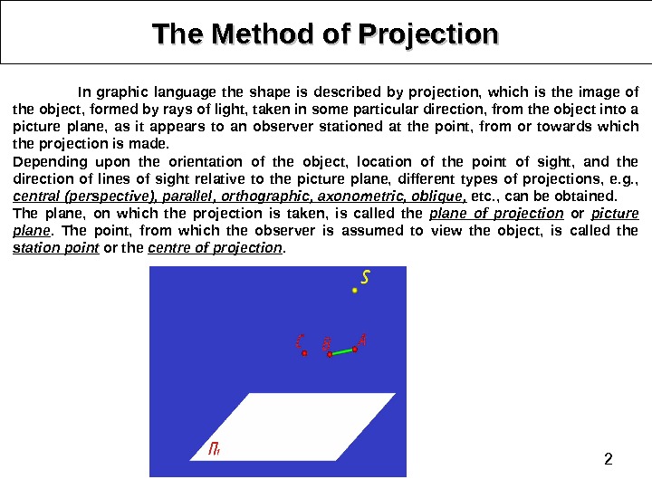
2 The Method of Projection In graphic language the shape is described by projection, which is the image of the object, formed by rays of light, taken in some particular direction, from the object into a picture plane, as it appears to an observer stationed at the point, from or towards which the projection is made. Depending upon the orientation of the object, location of the point of sight, and the direction of lines of sight relative to the picture plane, different types of projections, e. g. , central (perspective), parallel, orthographic, axonometric, oblique, etc. , can be obtained. The plane, on which the projection is taken, is called the plane of projection or picture plane. The point, from which the observer is assumed to view the object, is called the station point or the centre of projection.
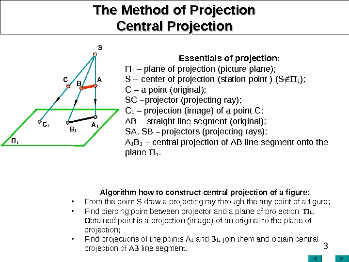
3 The Method of Projection Central PP rojection Essentials of projection : П 1 – plane of projection (picture plane ); S – cent e r of projection (station point ) ( S 1 ); C – a point ( original ); SC – projector (projecting ray) ; C 1 – projection (image) of a point C; АВ – straight line segment ( original ); SА, SB – projectors (projecting rays) ; А 1 В 1 – central projection of АВ line segment onto the plane 1. Algorithm how to construct central projection of a figure : • From the point S draw a projecting ray through the any point of a figure ; • Find piercing point between projector and a plane of projection 1. Obtained point is a projection (image) of an original to the plane of projection ; • Find projections of the points А 1 and В 1 , join them and obtain central projection of АВ line segment. П 1 A 1 B 1 C 1 S
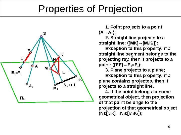
4 Properties of Projection П 1 1. Point projects to a point (А→А 1 ); 2. Straight line projects to a straight line : ([МК]→[М 1 К 1 ]); Exception to this property: if a straight line segment belongs to the projecting ray, then it projects to a point : ([Е F ]→ E 1 = F 1 ) ; 3. Plane projects to a plane; Exception to this property: if a plane contains projectos, then it projects to a straight line. 4. If the point belongs to some geometrical object, then projection of that point belongs to the projection of that geometrical object ( N є [ МК ]→ N 1 є [ М 1 К 1 ] ) ; E 1 =F 1 A 1 M 1 K 1 N 1 L =L 1 F E A K M NS
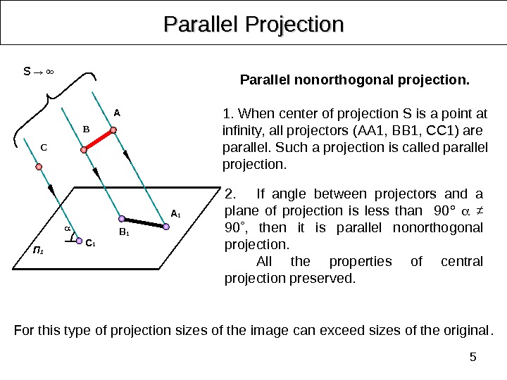
5 Parallel Projection 2. If angle between projectors and a plane of projection is less than 90° ≠ 90 , then it is p arallel nonorthogonal projection. All the properties of central projection preserved. For this type of projection sizes of the image can exceed sizes of the original. Parallel nonorthogonal projection. 1. When center of projection S is a point at infinity, all projectors (АА 1, ВВ 1, СС 1) are parallel. Such a projection is called parallel projection. A B C П 1 C 1 B 1 A 1 S → ∞
6 Parallel Projection
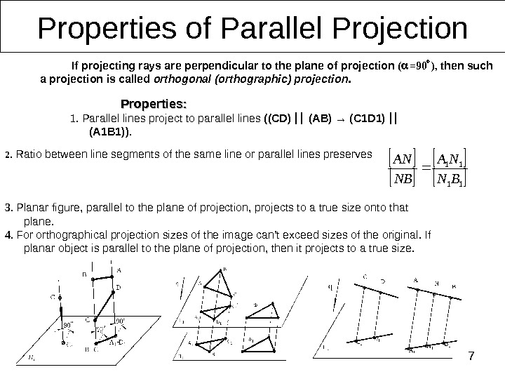
72. Ratio between line segments of the same line or parallel lines preserves 3. Planar figure, parallel to the plane of projection, projects to a true size onto that plane. 4. For orthographical projection sizes of the image can’t exceed sizes of the original. If planar object is parallel to the plane of projection, then it projects to a true size. Properties of Parallel Projection Properties : : 1. Parallel lines project to parallel lines (( CD ) ( AB ) → ( C 1 D 1) (А 1 В 1)). 11 11 BN NA NB AN If projecting rays are perpendicular to the plane of projection ( =90 ) , then such a projection is called orthogonal (orthographic) projection.
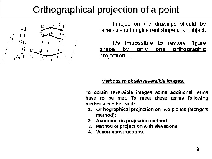
8 Orthographical projection of a point Images on the drawings should be reversible to imagine real shape of an object. It’s impossible to restore figure shape by only one orthographic projection. Methods to obtain reversible images. . To obtain reversible images some additional terms have to be met. To meet these terms following methods can be used: 1. 1. Orthographical projection on two planes ( ( Monge’s method ); ); 2. 2. Axonometric projection method ; ; 3. 3. Method of projection with elevations. . 4. 4. Vector constructions.
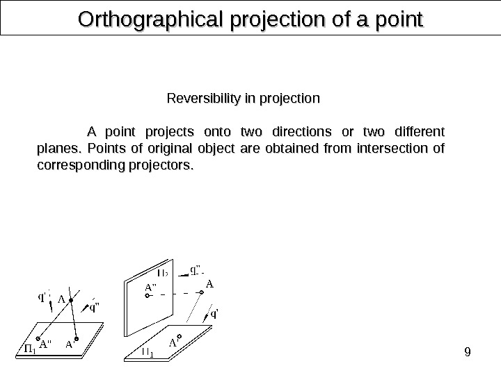
9 Orthographical projection of a point Reversibility in projection A point projects onto two directions or two different planes. Points of original object are obtained from intersection of corresponding projectors.
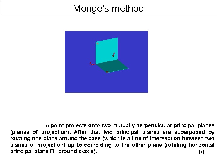
10 Monge’s method A point projects onto two mutually perpendicular principal planes (planes of projection). After that two principal planes are superposed by rotating one plane around the axes (which is a line of intersection between two planes of projection) up to coinciding to the other plane (rotating horizontal principal plane П 1 around х -axis).
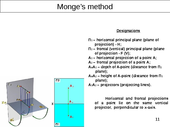
11 Monge’s method Designations П 1 – horizontal principal plane (plane of projection) — H ; П 2 – frontal (vertical) principal plane (plane of projection — F (V) ; А 1 – horizontal projection of a point А; А 2 – frontal projection of a point А; A x A 1 – depth of A-point ( distance from П 2 — plane ); A x A 2 – height of A-point ( distance from П 1 — plane ); A 1 A 2 – projectors (projecting lines). Horizontal and frontal projections of a point lie on the same vertical projector, perpendicular to x-axis.
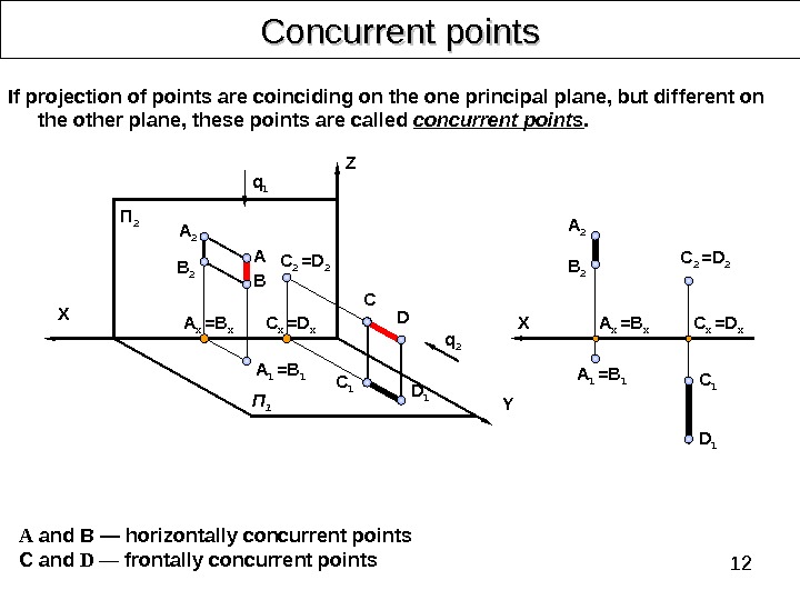
12 Concurrent points А and В — horizontally concurrent points C and D — frontally concurrent points If projection of points are coinciding on the one principal plane, but different on the other plane, these points are called concurrent points. A 2 BA C 1 D 1 C D YП 2 B 2 П 1 C 2 =D 2 q 2 q 1 X Z D 1 C 1 A 2 A 1 =B 1 X C x =D x. A x = B x. C 2 =D 2 A 1 =B 1 A x = B x C x =D x
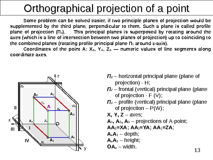
13 Orthographical projection of a point Some problem can be solved easier, if two principle planes of projection would be supplemented by the third plane, perpendicular to them. Such a plane is called profile plane of projection (П 3 ). This principal planes is superposed by rotating around the axes (which is a line of intersection between two planes of projection) up to coinciding to the combined planes (rotating profile principal plane П 1 around z-axis). Coordinates of the point А: X A , Y A , Z A — numeric values of line segments along coordinate axes. П 1 – horizontal principal plane (plane of projection) — H ; П 2 – frontal (vertical) principal plane (plane of projection — F (V) ; П 3 – profile (vertical) principal plane (plane of projection – P(W) ; X , Y , Z – axes ; A 1 , A 2 , A 3 – projections of А -point ; АА 3 = XA ; АА 2 = YA ; АА 1 = ZA ; A x A 1 – depth ; A x A 2 – height ; ОА x – width. A 2 II IIIx IV I y. OA z A x A z A 3 A y A 1 П 2 П 1 П 3 Z AY A X
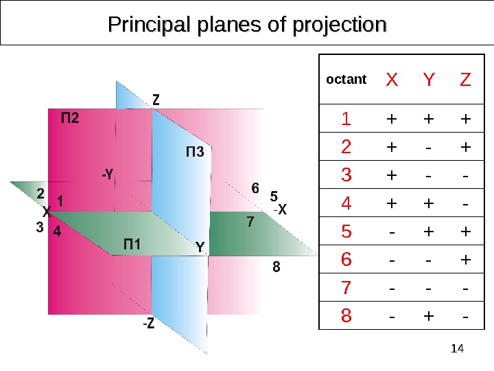
14 octant X Y Z 1 + + + 2 + — + 3 + — — 4 + + — 5 — + + 6 — — + 7 — — — 8 — + -Principal planes of projection
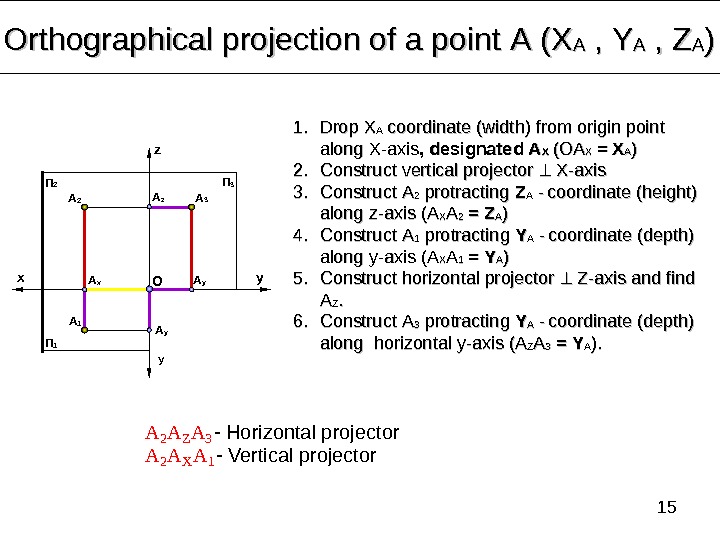
15 Orthographical projection of a point А (Х АА , , YY AA , , ZZ AA )) A 2 A Z A 3 — Horizontal projector A 2 A X A 1 — Vertical projectorx yz y. П 1 П 2 П 3 1. 1. Drop ХХ АА coordinate (width) from origin point along X-axis , , designated А А ХХ (ОА ХХ = Х АА )) 2. 2. Construct vertical projector X-axis 3. 3. Construct АА 22 protracting ZZ АА — coordinate (height) along z-axis (А(А ХХ АА 22 = = ZZ АА )) 4. 4. Construct АА 11 protracting YY АА — coordinate (depth) along y-axis (А(А ХХ АА 11 = = YY АА )) 5. 5. Construct horizontal projector Z-axis and find АА ZZ. . 6. 6. Construct А А 33 protracting YY АА — coordinate (depth) along horizontal y-axis (А(А ZZ АА 33 = = YY АА ). ). A 2 A 1 A 3 A x A y. O A z
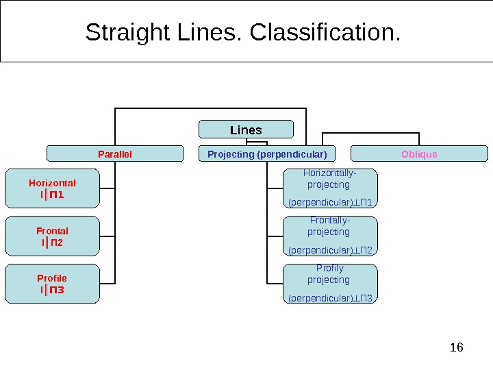
16 Straight Lines. Classification. Lines Parallel Projecting (perpendicular) Oblique Horizontal l ║ П 1 Frontal l ║ П 2 Profile l ║ П 3 Horizontally- projecting (perpendicular) ┴ П 1 Frontally- projecting (perpendicular) ┴ П 2 Profily projecting (perpendicular) ┴ П
17 Orthographic projection of a Straight Line. . Horizontal line Horizontal (horizontally parallel) – straight line, parallel to П 1. x O Y’Z Y Horizontal line projects onto П 1 to a True Length. Angles and on that projection are true angles between a line and principal planes of projection П 2 and П 3. Horizontal line projects onto П 2 and П 3 to horizontal line segments of a length, less then a true size. A O X z A 1 B 1 A 2 B B 3 A 3 y A 3 B 3 h 3 h 1 B 1 A 1 A 2 B 2 h
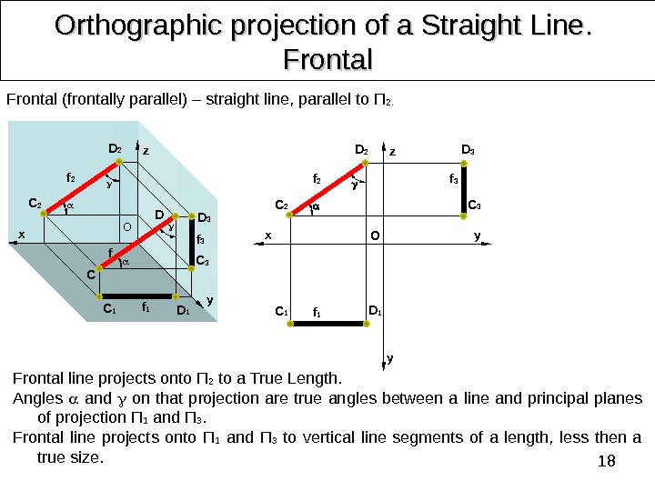
18 Orthographic projection of a Straight Line. . Frontal line projects onto П 2 to a True Length. Angles and on that projection are true angles between a line and principal planes of projection П 1 and П 3. Frontal line projects onto П 1 and П 3 to vertical line segments of a length, less then a true size. Frontal (frontally parallel) – straight line, parallel to П 2. D 2 yz x O f C DC 2 f 2 D 2 C 2 f 2 D 1 C 1 D 3 C 3 z x y y O C 1 D 1 f 1 D 3 C 3 f 3 f 1 f
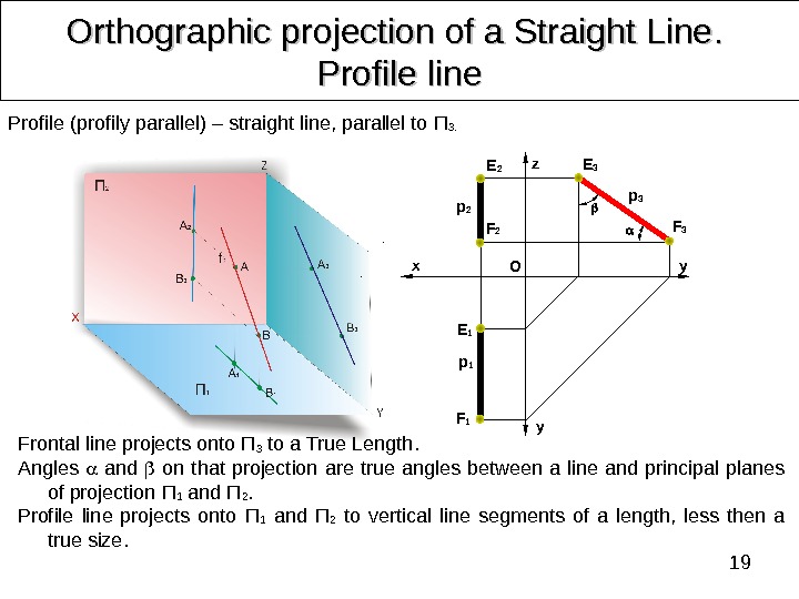
19 Orthographic projection of a Straight Line. . Profile line Profile (profily parallel) – straight line, parallel to П 3. Frontal line projects onto П 3 to a True Length. Angles and on that projection are true angles between a line and principal planes of projection П 1 and П 2. Profile line projects onto П 1 and П 2 to vertical line segments of a length, less then a true size. z x y y OE 2 F 2 p 2 F 3 E 3 p 3 F 1 E 1 p
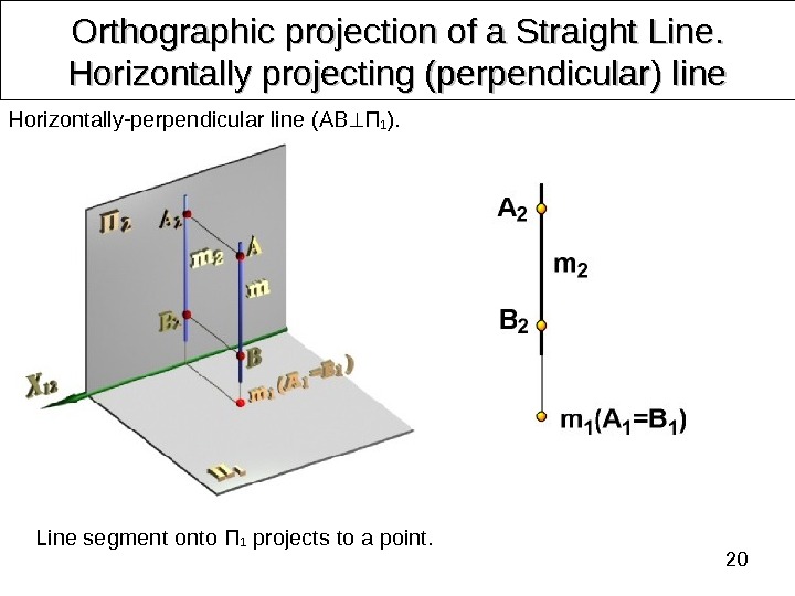
20 Orthographic projection of a Straight Line. . Horizontally projecting (perpendicular) line Line segment onto П 1 projects to a point. Horizontally-perpendicular line ( AB П 1 ).
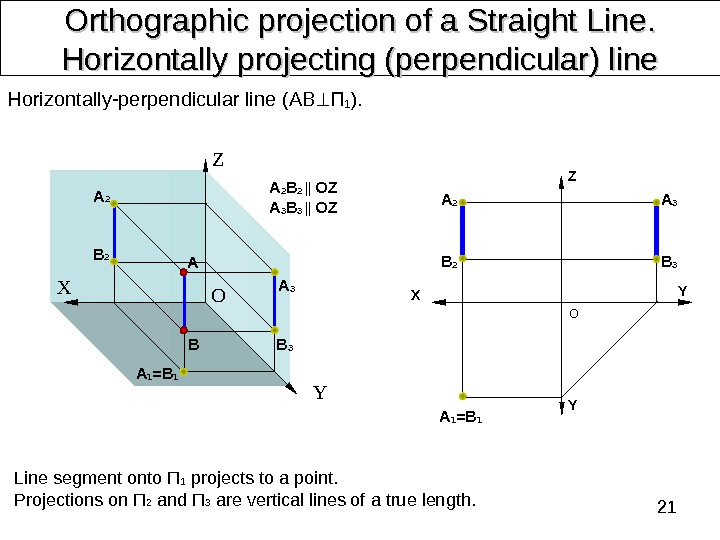
21 Orthographic projection of a Straight Line. . Horizontally projecting (perpendicular) line Line segment onto П 1 projects to a point. Projections on П 2 and П 3 are vertical lines of a true length. Horizontally-perpendicular line ( AB П 1 ). Z X Y Z Х О ОA 2 BA A 3 B 3 A 1 =B 1 A 2 B 2 || OZ A 3 B 3 || OZ Y YB 3 A 3 A 2 B 2 A 1 =
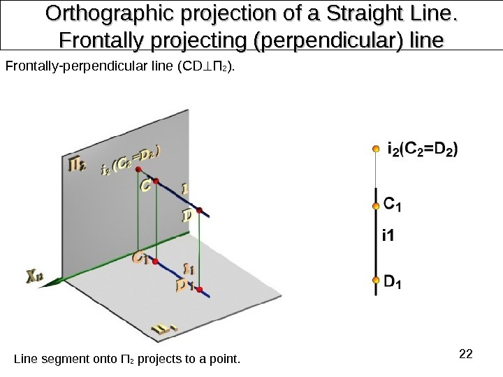
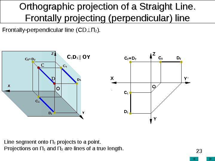
22 Orthographic projection of a Straight Line. . Frontally projecting (perpendicular) line Frontally-perpendicular line ( CD П 2 ). Line segment onto П 2 projects to a point.
23 Orthographic projection of a Straight Line. . Frontally projecting (perpendicular) line Frontally-perpendicular line ( CD П 2 ). Line segment onto П 2 projects to a point. Projections on П 1 and П 3 are lines of a true length. X YZ O Y ‘C 2 = D 2 X C DZ YO D 3 C 3 C 1 D 1 C 2 = D 2 C 1 D 1 || OY
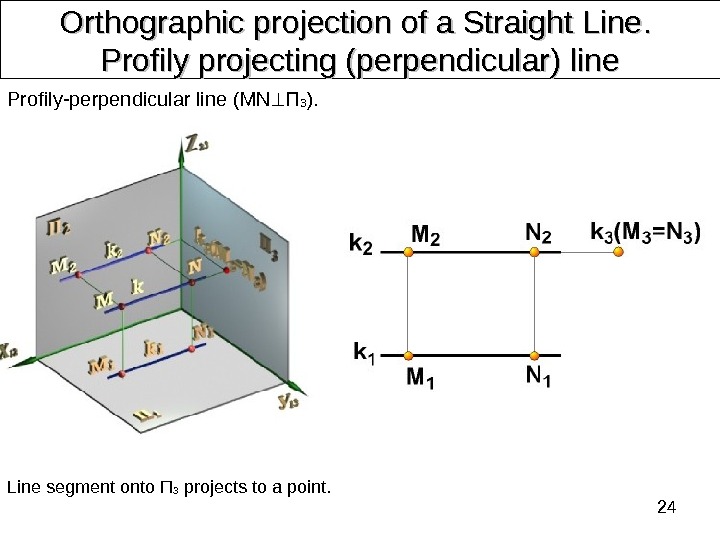
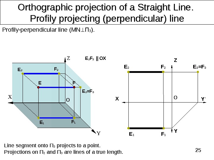
24 Orthographic projection of a Straight Line. . Profily projecting (perpendicular) line Profily-perpendicular line ( MN П 3 ). Line segment onto П 3 projects to a point.
25 Orthographic projection of a Straight Line. . Profily projecting (perpendicular) line Profily-perpendicular line ( MN П 3 ). Line segment onto П 3 projects to a point. Projections on П 2 and П 3 are lines of a true length. E 2 F 2 || OX E O YFZ X X Y Y ‘Z OE 2 F 2 E 1 F 1 E 3 =
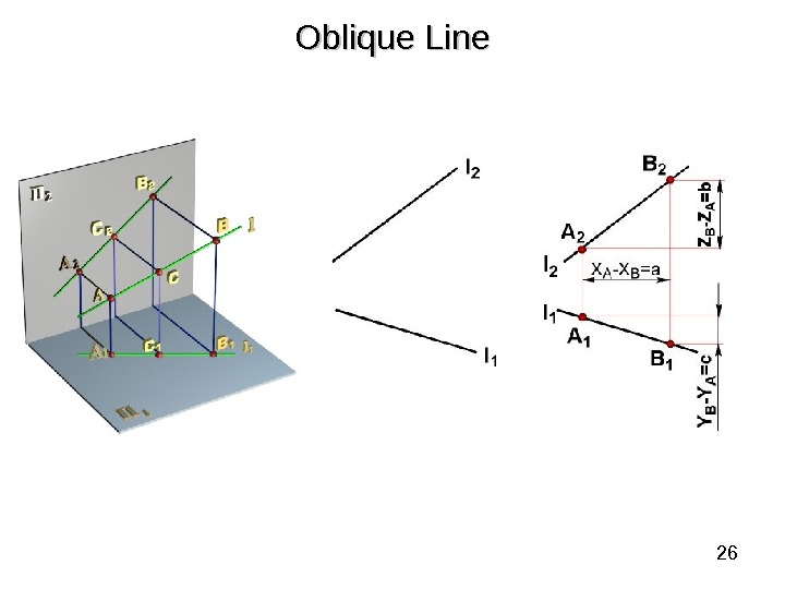
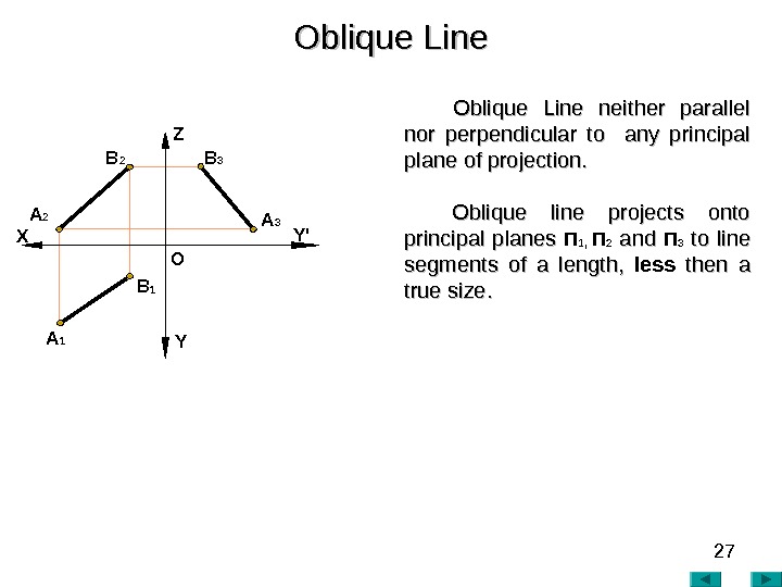
26 Oblique Line
27 Oblique Line neither parallel nor perpendicular to any principal plane of projection. Oblique line projects onto principal planes П 1, П 2 andand П 3 to line segments of a length, less then a true size. . Oblique Line A 2 A 1 X Z Y Y’ O
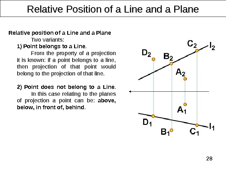
28 Relative Position of a Line and a Plane Relative position of a Line and a Plane Two variants: 1) Point belongs to a Line. From the property of a projection it is known: if a point belongs to a line, then projection of that point would belong to the projection of that line. 2) Point does not belong to a Line. In this case relating to the planes of projection a point can be: above , below , in front of , behind.
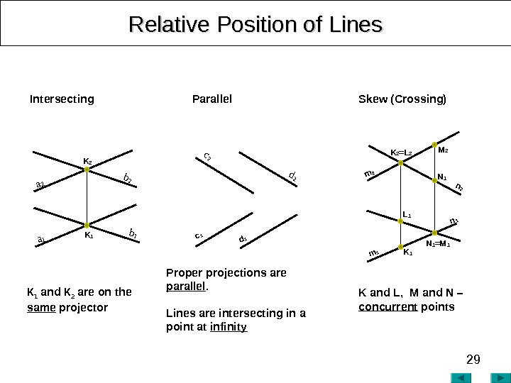
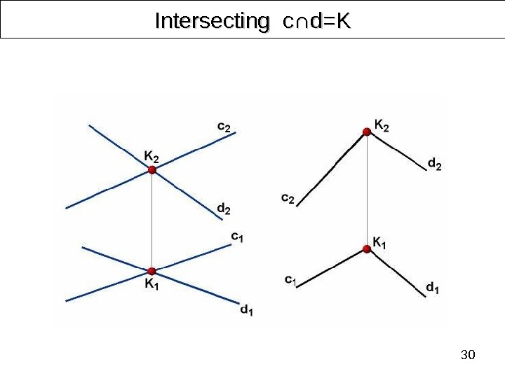
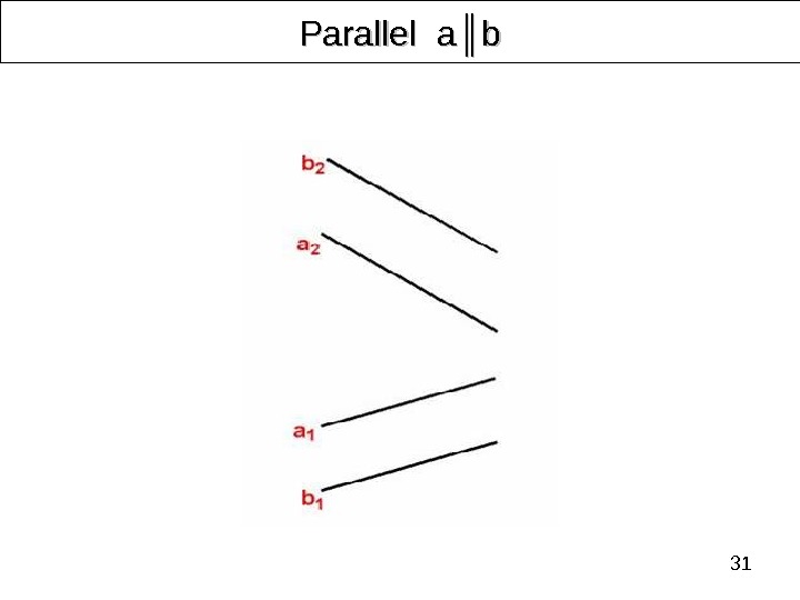
29 Relative Position of Lines K and L , M and N – concurrent points Proper projections are parallel. Lines are intersecting in a point at infinity. К 1 and К 2 are on the same projector Intersecting Parallel Skew (Crossing) K 2 = L 2 m 1 m 2 K 1 n 2 n 1 M 2 N 1 = M 1 L 1 K 2 a 1 a 2 K 1 b 2 d 2 c 1 d
30 Intersecting с∩ с∩ d=Kd=K
31 Parallel aa ║║ bb
32 Skew (Crossing) ――
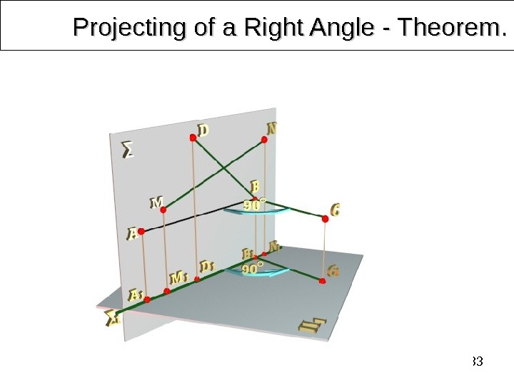
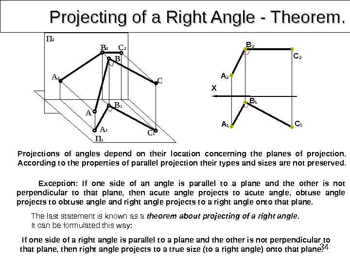
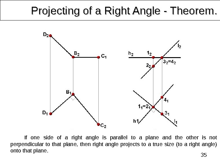
33 Projecting of a Right Angle — Theorem. .
34 Projecting of a Right Angle — Theorem. . Exception: If one side of an angle is parallel to a plane and the other is not perpendicular to that plane, then acute angle projects to acute angle, obtuse angle projects to obtuse angle and right angle projects to a right angle onto that plane. Projections of angles depend on their location concerning the planes of projection. According to the properties of parallel projection their types and sizes are not preserved. The last statement is known as a theorem about projecting of a right angle. It can be formulated this way: A 2 B 1 B 2 B C 1 CП 2 П 1 A 1 A C 2 X B 1 А 1 C 1 C 2 B 2 А 2 If one side of a right angle is parallel to a plane and the other is not perpendicular to that plane, then right angle projects to a true size (to a right angle) onto that plane.
35 Projecting of a Right Angle — Theorem. . If one side of a right angle is parallel to a plane and the other is not perpendicular to that plane, then right angle projects to a true size (to a right angle) onto that plane.
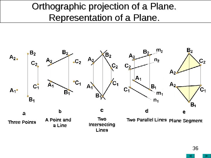
36 Orthographic projection of a Plane. Representation of a Plane. . bb A Point and a Lineaa Three Points cc Two Intersecting Lines dd Two Parallel Lines ee Plane Segment
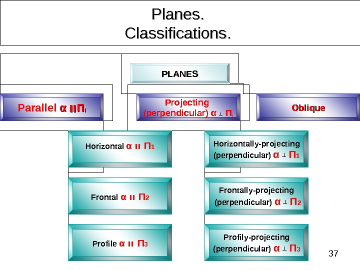
37 Planes. . Classifications. . PLANES Parallel αα װװ ΠΠ ii Projecting (perpendicular) α ┴ П i Oblique Horizontal α װ Π 1 Frontal α װ Π 2 Profile α װ Π 3 Horizontally-projecting (perpendicular) α ┴ Π 1 Frontally-projecting (perpendicular) α ┴ Π 2 Profily-projecting (perpendicular) α ┴ Π
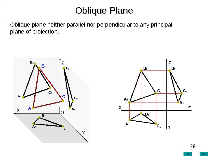
38 Oblique Plane Z Y’ YXOblique plane neither parallel nor perpendicular to any principal plane of projection. B 3 AA 2 CC 2 B A 3 C 3 Z YОB 2 A 1 C 1 B 1 X A 2 С
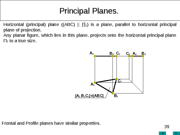
39 Principal Planes. . Horizontal (principal) plane ((ABC) || 1 ) is a plane, parallel to horizontal principal plane of projection. Any planar figure, which lies in this plane, projects onto the horizontal principal plane П 1 to a true size. Frontal and Profile planes have similar properties. С 3 A 3 B 3 A 2 B 2 С 2 | A 1 B 1 C 1 |=|ABC| A 1 С
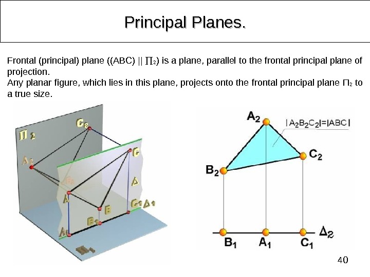
40 Principal Planes. . Frontal (principal) plane ((ABC) || 2 ) is a plane, parallel to the frontal principal plane of projection. Any planar figure, which lies in this plane, projects onto the frontal principal plane П 2 to a true size.
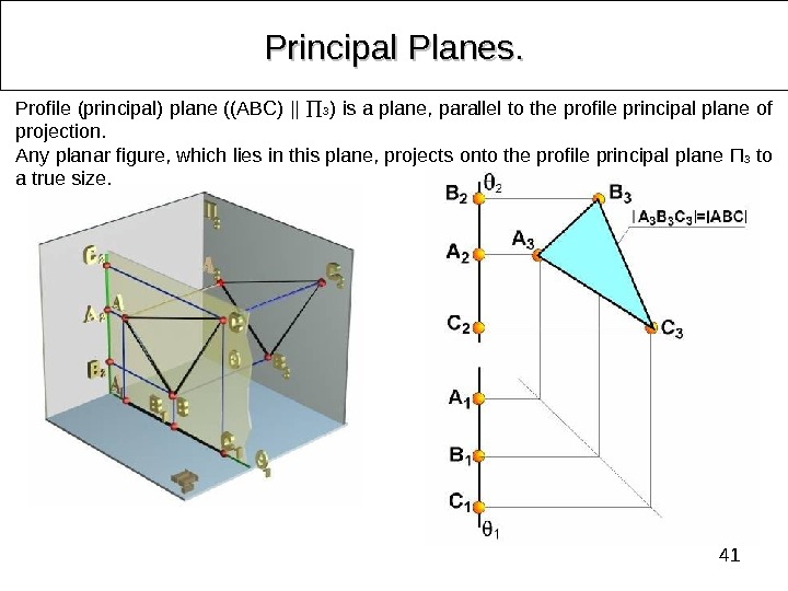
41 Principal Planes. . Profile (principal) plane ((ABC) || 3 ) is a plane, parallel to the profile principal plane of projection. Any planar figure, which lies in this plane, projects onto the profile principal plane П 3 to a true size.
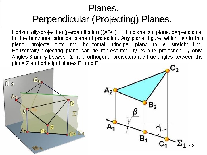
42 Planes. Perpendicular (Projecting) Planes. . Horizontally-projecting (perpendicular) ((ABC) 1 ) plane is a plane, perpendicular to the horizontal principal plane of projection. Any planar figure, which lies in this plane, projects onto the horizontal principal plane to a straight line. Horizontally-projecting plane can be represented by its one projection Σ 1 only. Angles and between Σ 1 and orthogonal projectors are true angles between the plane Σ and principal planes П 2 and П 3.
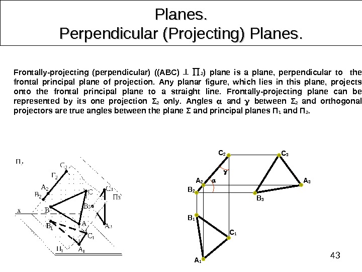
43 Planes. Perpendicular (Projecting) Planes. . B 2 С 2 A 2 С 1 A 1 B 1 Frontally-projecting (perpendicular) ((ABC) 2 ) plane is a plane, perpendicular to the frontal principal plane of projection. Any planar figure, which lies in this plane, projects onto the frontal principal plane to a straight line. Frontally-projecting plane can be represented by its one projection Σ 2 only. Angles and between Σ 2 and orthogonal projectors are true angles between the plane Σ and principal planes П 1 and П 3. С
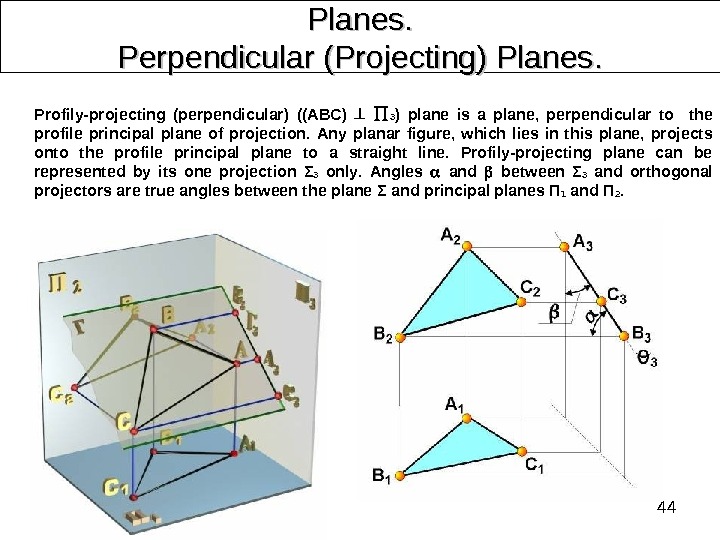
44 Planes. Perpendicular (Projecting) Planes. . Profily-projecting (perpendicular) ((ABC) 3 ) plane is a plane, perpendicular to the profile principal plane of projection. Any planar figure, which lies in this plane, projects onto the profile principal plane to a straight line. Profily-projecting plane can be represented by its one projection Σ 3 only. Angles and between Σ 3 and orthogonal projectors are true angles between the plane Σ and principal planes П 1 and П 2.
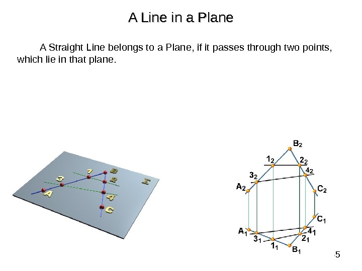
45 A Line in a Plane A Straight Line belongs to a Plane, if it passes through two points, which lie in that plane.
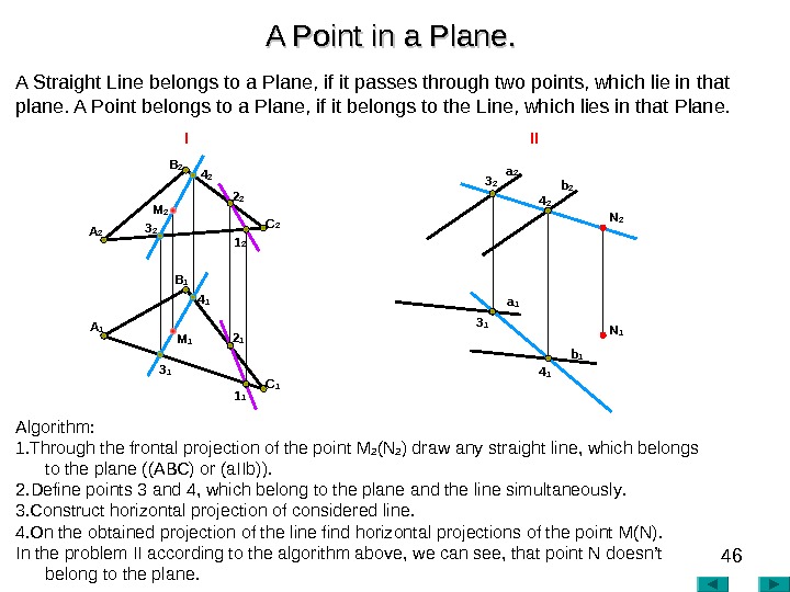
46 A Point in a Plane. . Algorithm : 1. Through the frontal projection of the point М 2 ( N 2 ) draw any straight line, which belongs to the plane ((АВС) or (а IIb )). 2. Define points 3 and 4, which belong to the plane and the line simultaneously. 3. Construct horizontal projection of considered line. 4. On the obtained projection of the line find horizontal projections of the point М( N ). In the problem II according to the algorithm above , we can see , that point N doesn’t belong to the plane. A 2 I II A 1 B 2 C 13 2 4 2 3 1 4 1 1 12 1 M 2 M 1 B 1 A Straight Line belongs to a Plane, if it passes through two points, which lie in that plane. A Point belongs to a Plane, if it belongs to the Line, which lies in that Plane. 2 2 1 2 a 2 N 1 b 2 b 1 a
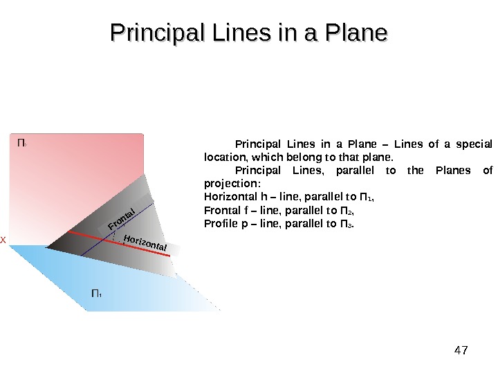
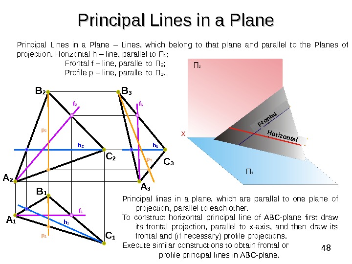
47 Principal Lines in a Plane – Lines of a special location, which belong to that plane. Principal Lines, parallel to the Planes of projection: Horizontal h – line , parallel to П 1 , Frontal f – line , parallel to П 2 , Profile p – line , parallel to П 3. Horizontal Frontal
48 Principal Lines in a Plane B 2 A 2 C 2 B 3 A 3 C 1 B 1 A 1 f 1 h 2 h 1 h 3 f 2 f 3 p 1 p 2 Principal lines in a plane, which are parallel to one plane of projection, parallel to each other. To construct horizontal principal line of ABC-plane first draw its frontal projection, parallel to x-axis, and then draw its frontal and (if necessary) profile projections. Execute similar constructions to obtain frontal or profile principal lines in ABC-plane. Horizontal Frontal. Principal Lines in a Plane – Lines, which belong to that plane and parallel to the Planes of projection. Horizontal h – line , parallel to П 1 ; Frontal f – line , parallel to П 2 ; Profile p – line , parallel to П 3.
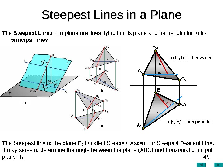
49 Steepest Lines in a Plane The Steepest Lines in a plane are lines, lying in this plane and perpendicular to its principal lines. The Steepest line to the plane П 1 is called Steepest Ascent or Steepest Descent Line. . It may serve to determine the angle between the plane (ABC) and horizontal principal plane П 1. h 1 х A 2 B 2 С 2 A 1 B 1 С 1 t 2 t 1 h 2 h (h 2 , h 1 ) – horizontal t (t 1 , t 2 ) – steepest linea b c
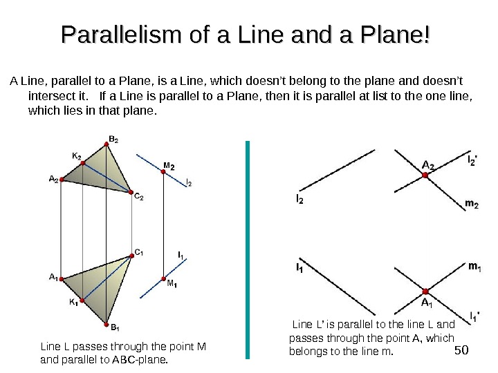
50 Parallelism of a Line and a Plane! A Line, parallel to a Plane, is a Line, which doesn’t belong to the plane and doesn’t intersect it. If a Line is parallel to a Plane, then it is parallel at list to the one line, which lies in that plane. Line L passes through the point M and parallel to ABC-plane. Line L’ is parallel to the line L and passes through the point A, which belongs to the line m.
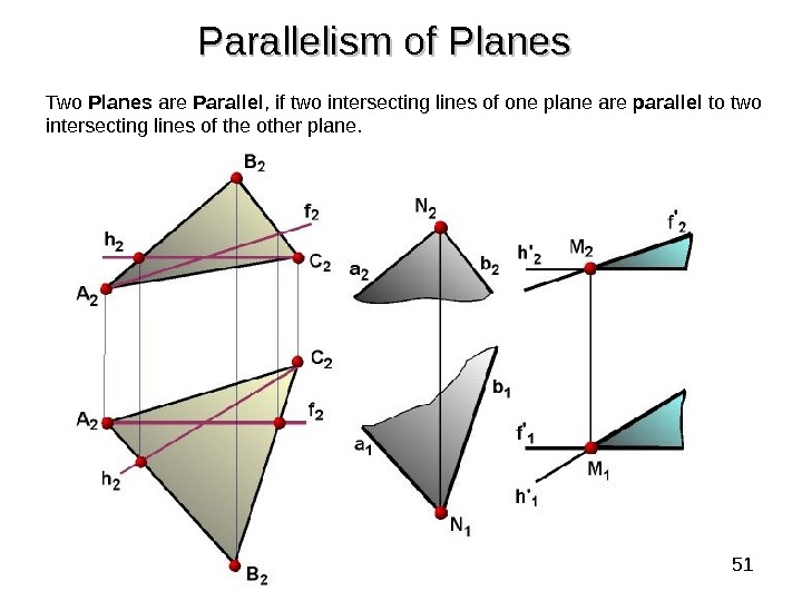
51 Two Planes are Parallel , if two intersecting lines of one plane are parallel to two intersecting lines of the other plane. Parallelism of Planes
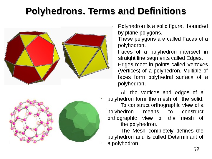
52 Polyhedrons. . Terms and Definitions Polyhedron is a solid figure, bounded by plane polygons. These polygons are called Faces of a polyhedron intersect in straight line segments called Edges meet in points called Vertexes (Vertices) of a polyhedron. Multiple of faces form polyhedral surface of a polyhedron. All the vertices and edges of a polyhedron form the mesh of the solid. To construct orthographic view of a polyhedron means to construct orthographic view of the mesh of the polyhedron. The Mesh completely defines the polyhedron and is called Determinant of a polyhedron.
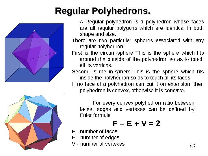
53 Regular Polyhedrons. . A Regular polyhedron is a polyhedron whose faces are all regular polygons which are identical in both shape and size. There are two particular spheres associated with any regular polyhedron. First is the circum-sphere This is the sphere which fits around the outside of the polyhedron so as to touch all its vertices. Second is the in-sphere This is the sphere which fits inside the polyhedron so as to touch all its faces. If no face of a polyhedron can cut it on extension, then polyhedron is convex, otherwise it is concave. For every convex polyhedron ratio between faces, edges and vertexes can be defined by Euler formula F – E + V = 2 F — number of faces E — number of edges V — number of vertexes
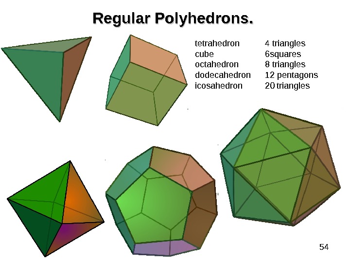
54 Regular Polyhedrons. . tetrahedron 4 triangles cube 6 squares octahedron 8 triangles dodecahedron 12 pentagons icosahedron 20 triangles
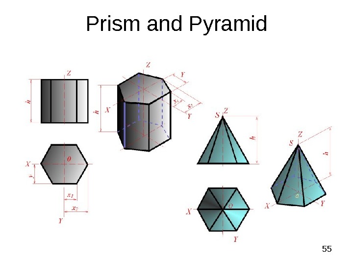
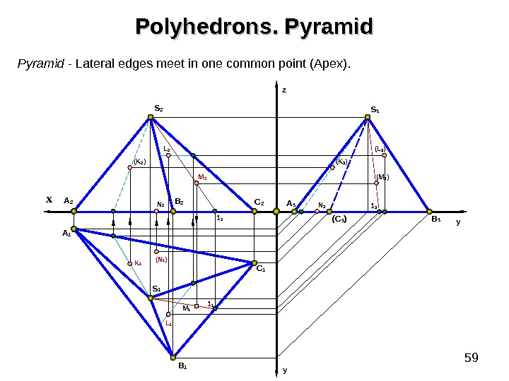
55 Prism and Pyramid
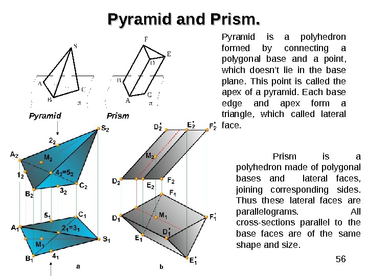
56 Pyramid and Prism. Pyramid is a polyhedron formed by connecting a polygonal base and a point, which doesn’t lie in the base plane. This point is called the apex of a pyramid. Each base edge and apex form a triangle, which called lateral face. Prism is a polyhedron made of polygonal bases and lateral faces, joining corresponding sides. Thus these lateral faces are parallelograms. All cross-sections parallel to the base faces are of the same shape and size. b. Pyramid Prism
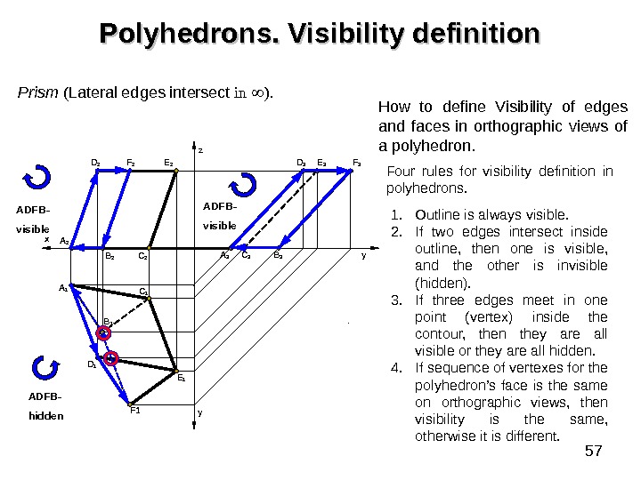
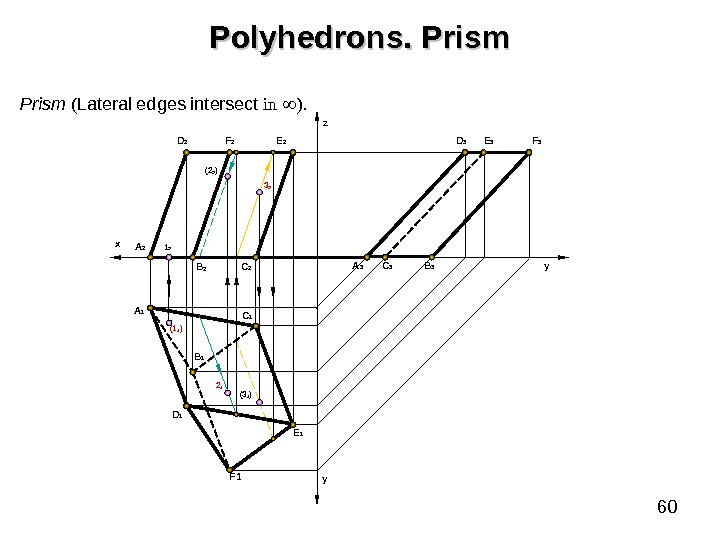
57 Polyhedrons. Visibility definition Prism ( Lateral edges intersect in ). A 1 D 1 C 2 C 1 y yz F 1 Е 1 Е 2 F 2 D 2 x A 2 B 1 А 3 С 3 B 3 F 3 Е 3 D 3 1. Outline is always visible. 2. If two edges intersect inside outline, then one is visible, and the other is invisible (hidden). 3. If three edges meet in one point (vertex) inside the contour, then they are all visible or they are all hidden. 4. If sequence of vertexes for the polyhedron’s face is the same on orthographic views, then visibility is the same, otherwise it is different. How to define Visibility of edges and faces in orthographic views of a polyhedron. Four rules for visibility definition in polyhedrons. ADFB- visible ADFB- hidden
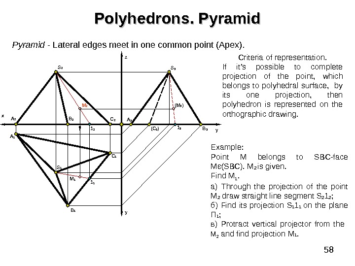
58 Polyhedrons. Pyramid — Lateral edges meet in one common point (Apex). B 1 y. A 2 A 1 x B 2 C 1 C 2 yz S 2 S 1 A 3 ( C 3 ) B 31 2 1 1 M 2 M 1 (M 3 ) 1 3 S 3 Example : Point M belongs to SBC-face Мє ( SBC). M 2 is given. Find M 1. a ) Through the projection of the point М 2 draw straight line segment S 2 1 2 ; б) Find its projection S 1 1 1 on the plane П 1 ; в) Protract vertical projector from the М 2 and find projection М 1. Criteria of representation. If it’s possible to complete projection of the point, which belongs to polyhedral surface, by its one projection, then polyhedron is represented on the orthographic drawing.
59 B 1 y. A 2 A 1 x B 2 C 1 C 2 yz S 2 S 1 A 3 ( C 3 ) B 31 2 1 1 M 2( K 2 ) K 1 ( N 1 )N 2 M 1 ( K 3 ) ( M 3 ) N 3 1 3( L 3 )S 3 Pyramid — Lateral edges meet in one common point (Apex). Polyhedrons. Pyramid L 2 L
60 Polyhedrons. Prism ( Lateral edges intersect in ). A 1 D 1 C 2 C 1 y yz F 1 Е 1 Е 2 F 2 D 2 x A 2 B 1(1 1 ) А 3 С 3 B 3 F 3 Е 3 D 3 1 2 2 1 (3 1 ) 3 2( 2 2 )