1 Copyright 2010 FUJITSUInterconnecting Cisco Networking Devices Part







layer_2_operations.ppt
- Размер: 3.5 Mегабайта
- Количество слайдов: 15
Описание презентации 1 Copyright 2010 FUJITSUInterconnecting Cisco Networking Devices Part по слайдам
 1 Copyright 2010 FUJITSUInterconnecting Cisco Networking Devices Part I (640 -822). Layer 2 operations. Fatkhullin Vildan Merkushev Gennady
 2 Copyright 2010 FUJITSUBroadcast and collusion domains 2 FUJITSU EYES ONLY If a switch receives a broadcast frame, the switch floods it out every active interface, just as it does for an unknown destination MAC address. All devices that receive this broadcast make up the broadcast domain. As more switches are connected together, the size of the broadcast domain increases. Collision domains create a similar problem. The more devices participating in a collision domain, the more collisions occur. Hubs create large collision domains. Switches, however, use a feature called microsegmentation to reduce the size of collision domains to a single switch port. Microsegmentation – division of a network into smaller segments, usually with the intention of increasing aggregation bandwidth to network devices.
 3 Copyright 2010 FUJITSUEthernet Communication PDU – Frame. Preamble – pattern of alternating 1 and 0 bits used to synchronize timing. SFD – marks the end if the timing information and starts of the frame. Destination MAC Source MAC Length / Type type value indicates which protocol will receive the data. the length indicates the number of bytes of data that follows this field. Encapsulated Data – contains the packet of information being sent. Each frame must be between 65 and 1518 bytes. FCS – frame check sequence. 3 FUJITSU EYES ONLY
 4 Copyright 2010 FUJITSUФормат MAC адреса МАС адрес состоит из 12 шестнадцатеричных значений. 3 первых байта – код производителя устройства 3 последних байта – уникальный идентификатор устройства 4 FUJITSU EYES ONLY
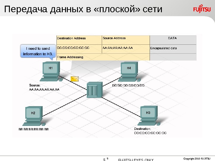
 5 Copyright 2010 FUJITSUПередача данных в «плоской» сети 5 FUJITSU EYES ONLY
 6 Copyright 2010 FUJITSUBroadcast and collusion domains 6 FUJITSU EYES ONLY
 7 Copyright 2010 FUJITSUHow switch works. When a host connects to a switch port, the switch creates a dedicated connection. When two connected hosts communicate with each other, the switch consults the switching table and establishes a virtual connection, or microsegment, between the ports. Switches can support either symmetric or asymmetric switching. Symmetric – switches that have ports of all the same speeds Asymmetric – connections between ports of different speeds Switches can handle traffic on the second and third layers of OSI. Multilayer switching combines hardware-based switching and hardware-based routing in the same device 7 FUJITSU EYES ONLY
 8 Copyright 2010 FUJITSUTypes of switching. When switching was first introcuded, a switch could support one of two major methods to forward a frame from one port to another. The two methods are store and forward and cut-through switching. Store and forward entire frame is read and stored in memory before being sent to the destination device switch checks the integrity of the bits in the frame by recalculating the cyclic redundancy check (CRC) value this method keeps damaged frames from being switched to other network segments the highest amount of latency Cut-through fast-forward fragment-free 8 FUJITSU EYES ONLY
 9 Copyright 2010 FUJITSUTypes of switching. Fast-forward the fastest method of switching switch forwards the frames out the destination port as soon as it reads the destination MAC address the lowest latency forwards collision fragments and damaged frames Fragment-free switch reads the first 64 bytes of the frame before it begins to forward it out the destination port Smaller frames are usually the result of a collision and are called “runts” Checking the first 64 bytes ensures that the switch does not forward collision fragments latency is in the middle of other methods fast-forward switching would be the preferred method 9 FUJITSU EYES ONLY
 10 Copyright 2010 FUJITSUTypes of switching. Adaptive Cut-through These switches begin by forwarding traffic using the fast-forward method to achieve the lowest latency possible. Even though the switch does not check for errors before forwarding the frame, it recognized the errors and stores an error counter in memory. It compares the number of errors found to a predefined threshold value. If the number of errors exceeds the threshold value, the switch has forwarded an unacceptable number of errors. In this situation, the switch modifies itself to perform store and forward switching. If the number of errors drops back below the threshold, the switch reverts back to fast-forward mode. 10 FUJITSU EYES ONLY
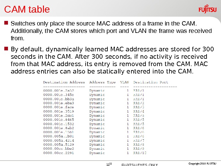
 11 Copyright 2010 FUJITSUCAM table Switches only place the source MAC address of a frame in the CAM. Additionally, the CAM stores which port and VLAN the frame was received from. By default, dynamically learned MAC addresses are stored for 300 seconds in the CAM. After 300 seconds, if no activity is received from that MAC address, its entry is removed from the CAM. MAC address entries can also be statically entered into the CAM. 11 FUJITSU EYES ONLY
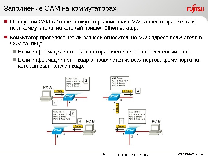
 12 Copyright 2010 FUJITSUЗаполнение CAM на коммутаторах При пустой CAM таблице коммутатор записывает MAC адрес отправителя и порт коммутатора, на который пришел Ethernet кадр. Коммутатор проверяет нет ли записей относительно MAC адреса получателя в CAM таблице. Если информация есть – кадр отправляется через определенный порт. Если информации нет – кадр отправляется из всех портов, кроме порта на который был получен кадр. 12 FUJITSU EYES ONLY
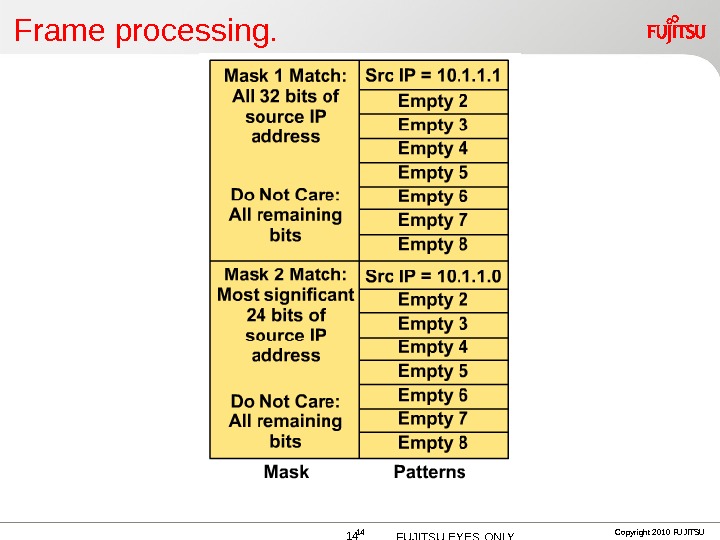
 13 Copyright 2010 FUJITSUFrame processing. When a Layer 2 switch receives a frame on a port, it places that frame in one of the port’s ingress queues. When the switch decides which port that frame should sent out of, it places the frame in that port’s egress queue. If the destination MAC address in the frame is not in the MAC address table, the frame is placed in the egress queue of all ports and is flooded throughout the network. Before a Layer 2 switch can take a frame from one port’s ingress queue to another port’s egress queue, it must consult two tables : Content Addressable Memory (CAM) , which is Cisco’s term for the MAC address table. It can also be referred to as the Layer 2 Forwarding Table. Ternary Content Addressable Memory (TCAM), which contains access lists that can filter frames by MAC address, and Qo. S access lists to prioritize traffic. In multi-layer switches, the TCAM also contains access lists to filter frames based on IP address or TCP/UDP port. Both the CAM and TCAM are stored in RAM 13 FUJITSU EYES ONLY
 14 Copyright 2010 FUJITSUFrame processing. 14 FUJITSU EYES ONLY
 15 Copyright 2010 FUJITSU

