
Жуковский Москва. Heart surgical simulator Gerald D.


heart_surgical_simulator_2007.ppt
- Размер: 16.3 Mегабайта
- Количество слайдов: 49
Описание презентации Жуковский Москва. Heart surgical simulator Gerald D. по слайдам
Жуковский Москва. Heart surgical simulator
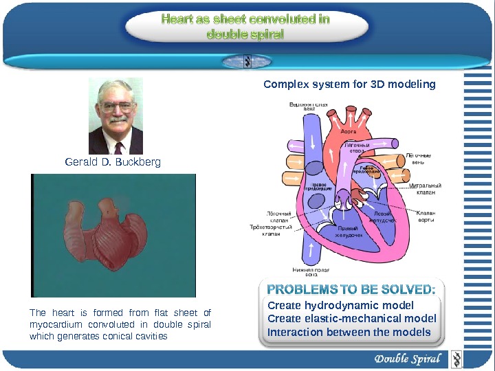
Gerald D. Buckberg The heart is formed from flat sheet of myocardium convoluted in double spiral which generates conical cavities Complex system for 3 D modeling Create hydrodynamic model Create elastic-mechanical model Interaction between the models
Four motion of the heat: Narrowing Shortening Lengthening Widening. Clockwise and counterclockwise spirals Unfolding of the rope and heart Spiral formation of the apical loop and the mathematical spiral
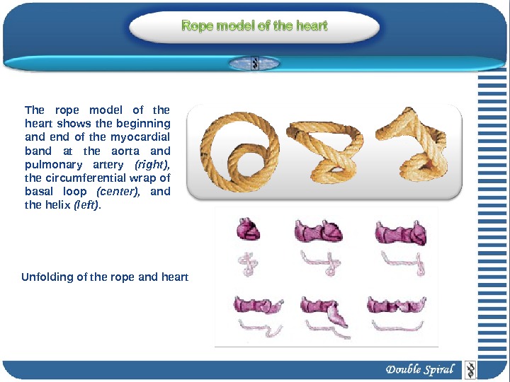
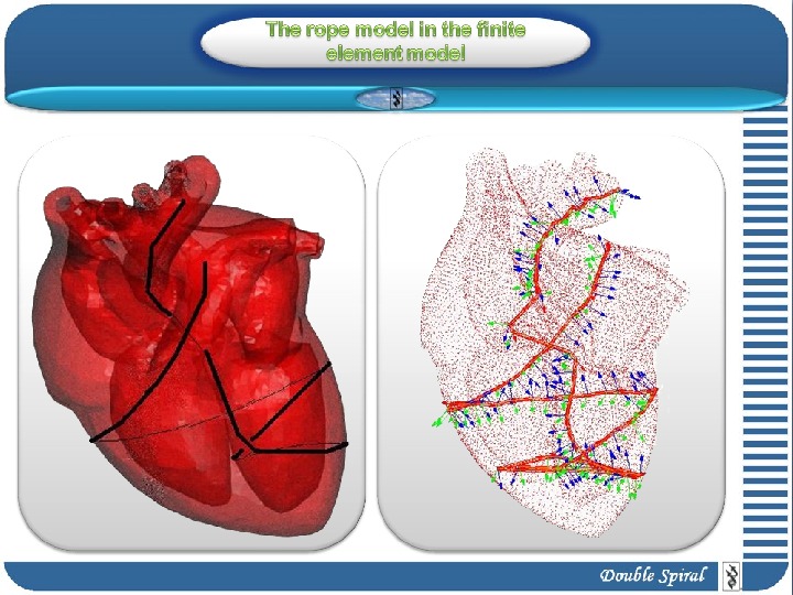
The rope model of the heart shows the beginning and end of the myocardial band at the aorta and pulmonary artery (right), the circumferential wrap of basal loop (center), and the helix (left). Unfolding of the rope and heart
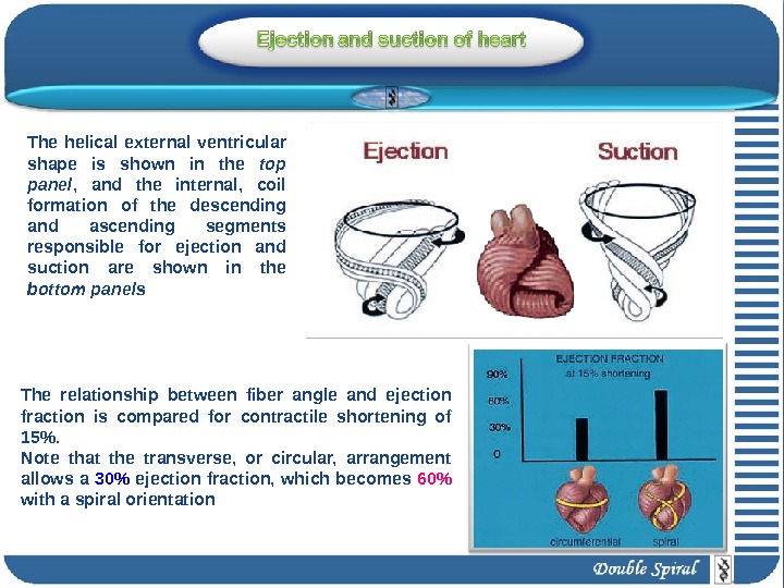
The relationship between fiber angle and ejection fraction is compared for contractile shortening of 15%. Note that the transverse, or circular, arrangement allows a 30% ejection fraction, which becomes 60% with a spiral orientation The helical external ventricular shape is shown in the top panel , and the internal, coil formation of the descending and ascending segments responsible for ejection and suction are shown in the bottom panels
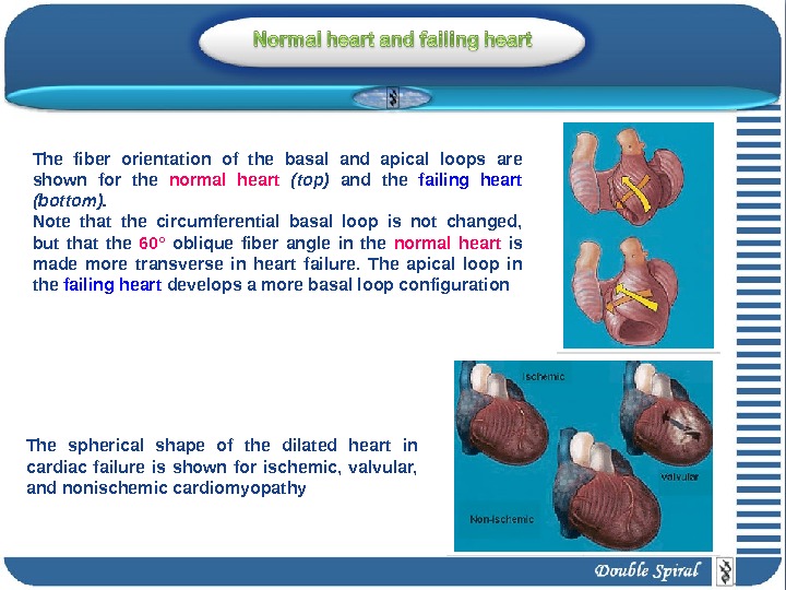
The fiber orientation of the basal and apical loops are shown for the normal heart (top) and the failing heart (bottom). Note that the circumferential basal loop is not changed, but that the 60° oblique fiber angle in the normal heart is made more transverse in heart failure. The apical loop in the failing heart develops a more basal loop configuration The spherical shape of the dilated heart in cardiac failure is shown for ischemic, valvular, and nonischemic cardiomyopathy
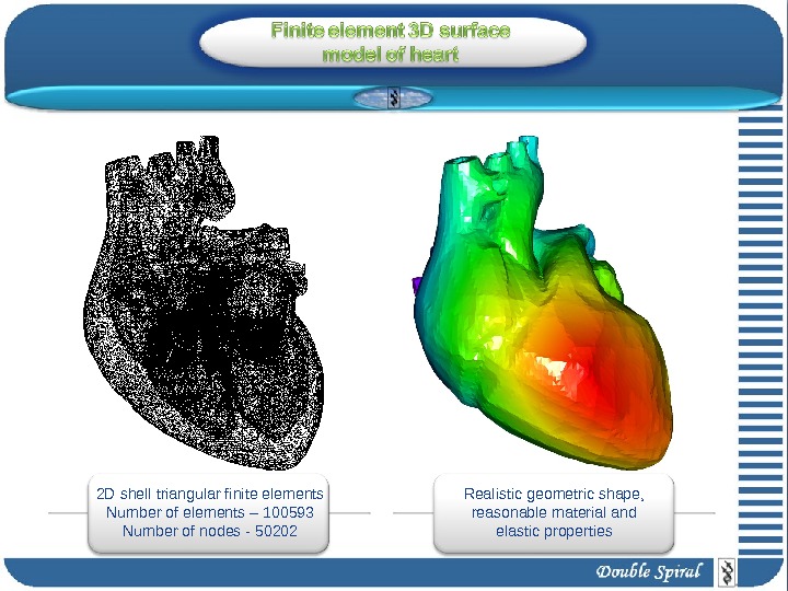
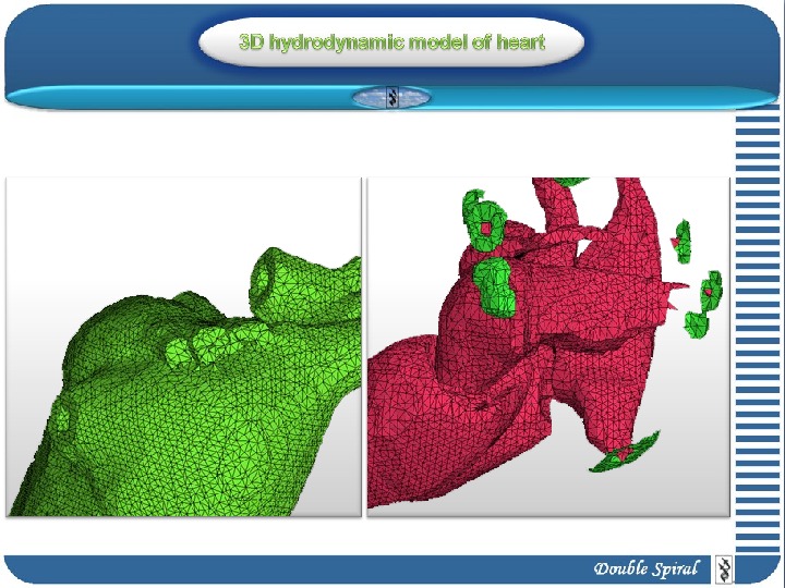
2 D shell triangular finite elements Number of elements – 100593 Number of nodes — 50202 Realistic geometric shape, reasonable material and elastic properties
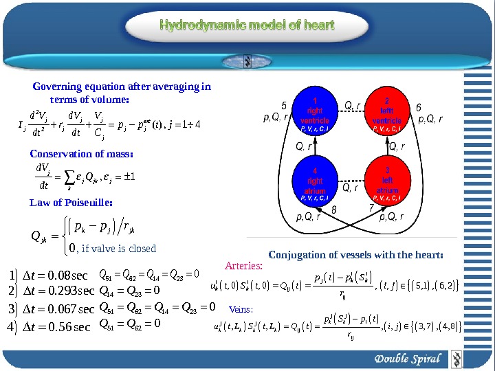
2 2( ) , 1 4 j j jext j j j d V d. V V I r p p t j dt Cdt , 1 j j jk j k d. V Q dt Governing equation after averaging in terms of volume: Conservation of mass: Law of Poiseuille: 0 k j jk jk p p r Q , if valve is closed 51 62 14 230 Q Q 51 62 14 230 Q Q 51 620 Q Q 1 0. 08 sect 2 0. 293 sec t 3 0. 067 sect 4 0. 56 sect , 0 , , 5, 1 , 6, 2 i i j k k i i k k ij ij p t p S u t S t Q t i j r Conjugation of vessels with the heart: , , 3, 7 , 4, 8 j jk k ij ij p S p t u t L S t L Q t i j r Arteries: Veins :
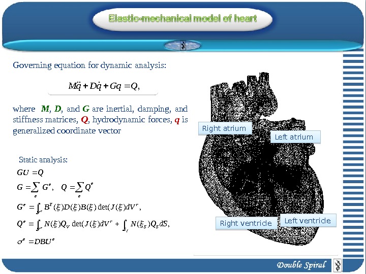
ee VSSS r V e V r. Te e ee e. DBU d. SQNd. VJQNQ d. VJBDBG QQGG QGU r fr , )()(det()( , )(det()()()(, , QGqq. Dq. MGoverning equation for dynamic analysis: where M , D , and G are inertial, damping, and stiffness matrices, Q , hydrodynamic forces, q is generalized coordinate vector Static analysis: Left ventricle Right ventricle Left atrium. Right atrium
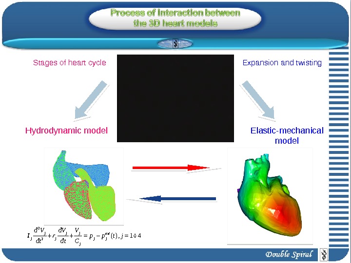
2 2( ) , 1 4 j j jextj j j d V d. V V I r p p t j dt Cdt Hydrodynamic model Elastic-mechanical model. Expansion and twisting. Stages of heart cycle
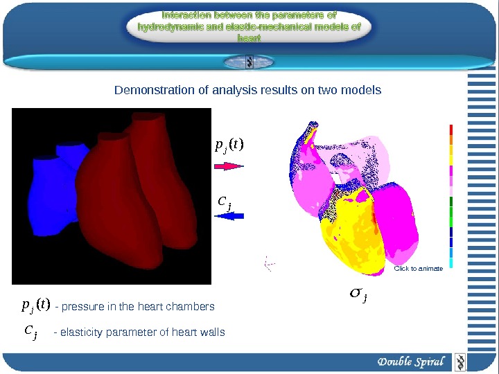
( )jp t- pressure in the heart chambers jc jc — elasticity parameter of heart walls j Demonstration of analysis results on two models Click to animate
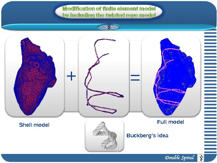
Shell model Full model Buckberg’s idea+ =
Analysis results
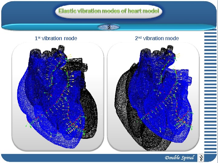
1 st vibration mode 2 nd vibration mode
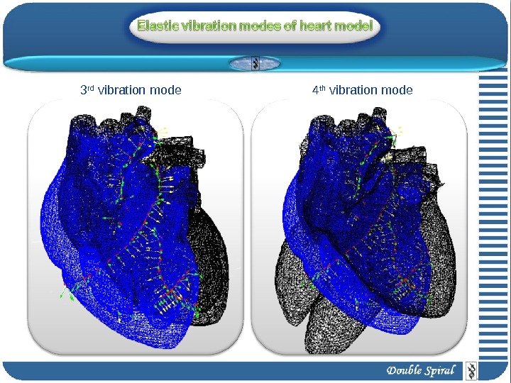
3 rd vibration mode 4 th vibration mode
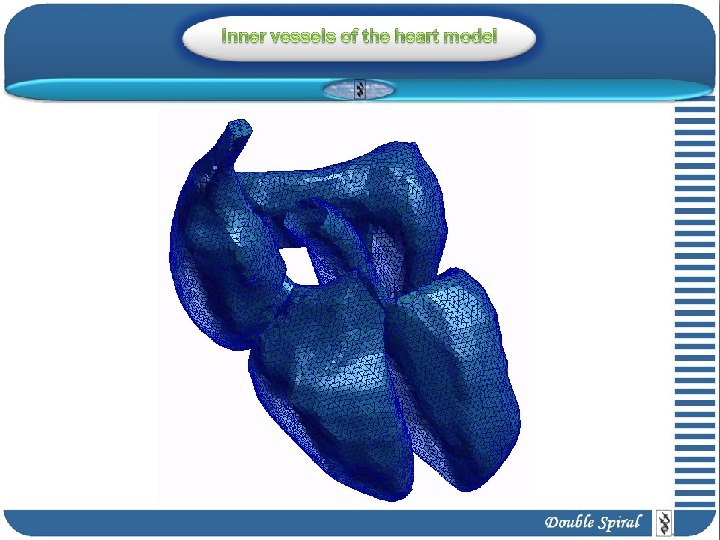
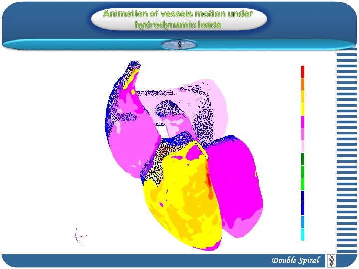
Vessel model Animation of displacements under pressure, obtained from hydrodynamic model
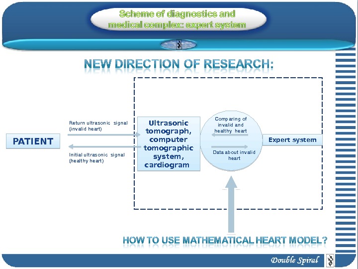
PATIENT Ultrasonic tomograph , computer tomographic system , cardiogram Expert system. Comparing of invalid and healthy heart Data about invalid heart. Initial ultrasonic signal (healthy heart)Return ultrasonic signal ( invalid heart)
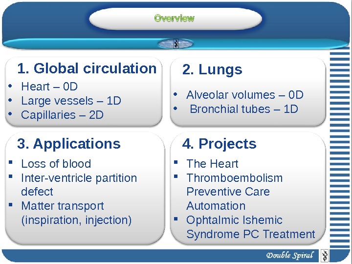
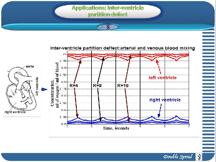
1. Global circulation • Heart – 0 D • Large vessels – 1 D • Capillaries – 2 D 3. Applications Loss of blood Inter-ventricle partition defect Matter transport (inspiration, injection) • Alveolar volumes – 0 D • Bronchial tubes – 1 D 4. Projects 2. Lungs The Heart Thromboembolism Preventive Care Automation Ophtalmic Ishemic Syndrome PC Treatment
1. Global circulation
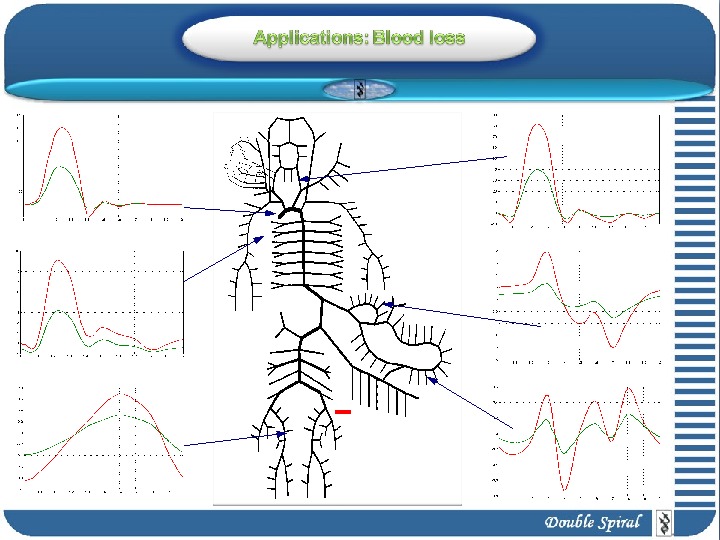
, , k k k iu S S t x S u r t x 2 , , 2 k k k i u u p t x S u r t x 2 , , ext k k kp t x c f S Mass conservation: Momentum conservation: “ Tube law” (state equation): 0 0 exp 1 1, ln , k k k k k S S f S S S k k k. S 216 k k k S u S d Loss of blood: Friction:
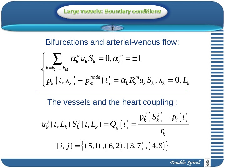
1 , . . . , 0, 1 , , 0, M m m k k k k node m k k k k u S p t x p t R u S x L The vessels and the heart coupling : Bifurcations and arterial-venous flow: , , j j k k ij ij p S p t u t L S t L Q t r , 5, 1 , 6, 2 , 3, 7 , 4, 8 i j
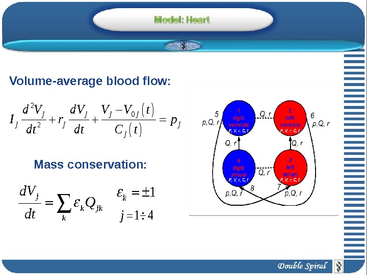
j k jk k d. V Q dt Volume-average blood flow: Mass conservation: 2 0 2 j j j j d V d. V V V t I r p dt dt C t 1 4 j 1 k
322 vessels 147 vessels
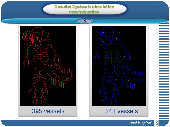
395 vessels 343 vessels
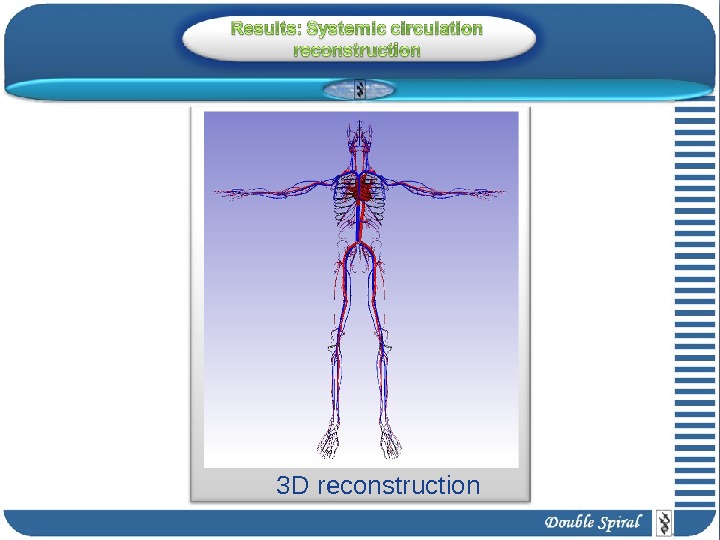
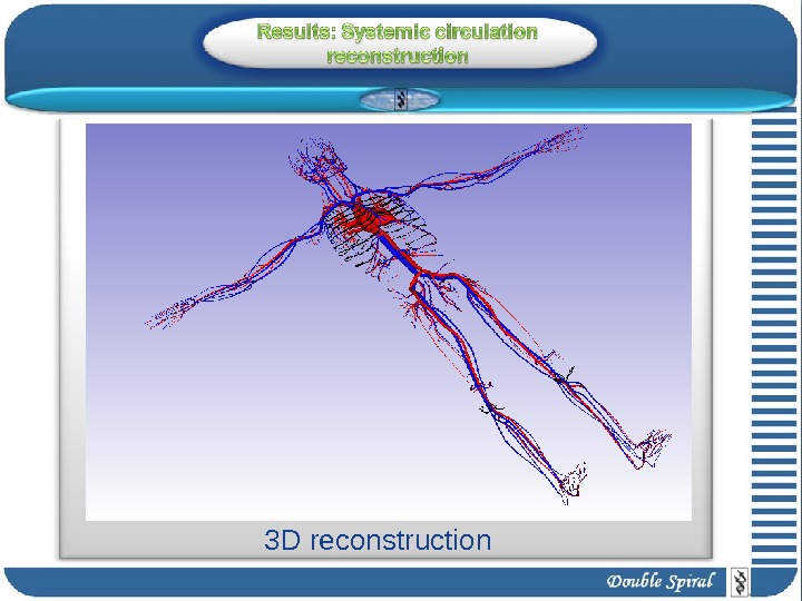
3 D reconstruction
3 D reconstruction
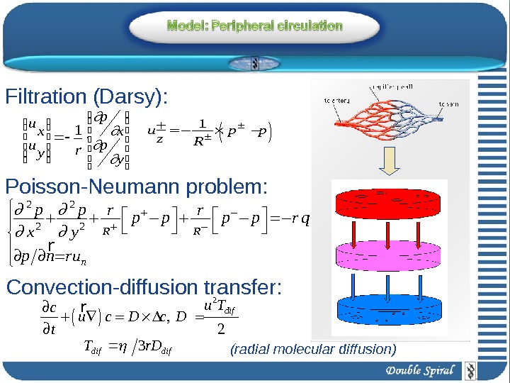
2 2 2 2 R R n p p r r p p r q x y p n ru r 1 u p p z. R y p x p ry u x u 1 2 , 2 difu T c u c D t r difdifr. DT 3 Filtration (Darsy): Convection-diffusion transfer: Poisson-Neumann problem: (radial molecular diffusion)
2. Lungs
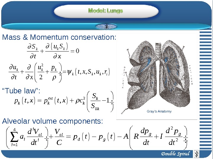
0 k k k u SS t x 2 , , 2 k k k i u u p t x S u r t x 2 0, , 1 ext k k k. S p t x c S Mass & Momentum conservation: “ Tube law”: 24 2 1 i g gal al i d gi i dp d pd V V a p t A R I dt C dt dt Alveolar volume components: Gray’s Anatomy
, , i i al K K i d. V u t L S t L dt 1, . . . , 0, 1 , M m m k k k k node m m k k k k u S p t x p t R u S Junction with alveolar volume: Junction: 1, 0 Tp t Nasopharynx: Gray’s Anatomy
3. Applications
0 sec 3 seclung (small veins) pulmonary veins 7 sec 20 sec 6 sec arm (arteries) arm
2 secarteries veinstissue 15 secarteries veinstissuesystemic arteries 0. 3 sec
4. Projects
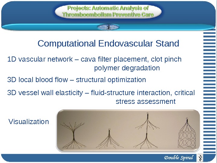
1 D vascular network – cava filter placement, clot pinch polymer degradation 3 D local blood flow – structural optimization 3 D vessel wall elasticity – fluid-structure interaction, critical stress assessment. Computational Endovascular Stand Visualization
Hydrodynamic model Stages of the heart cycle Elastic-mechanic al model Expansion and twisting. Unfolding the heart
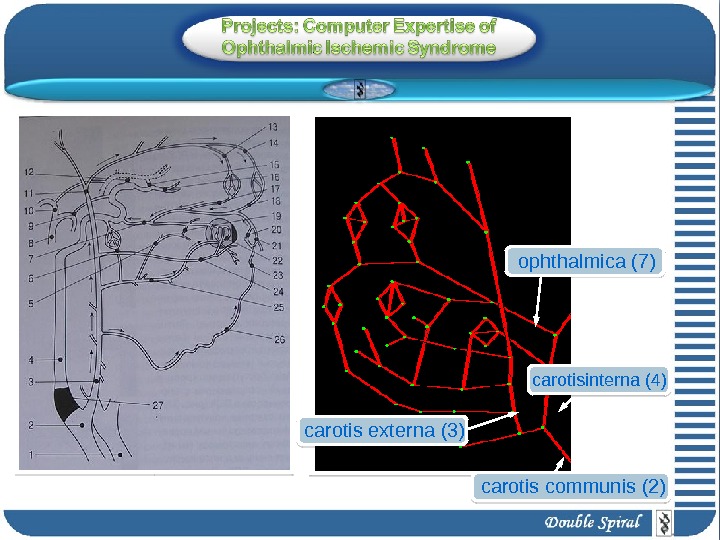
ophthalmica (7) carotis externa (3) carotis communis (2) с arotisinterna (4)
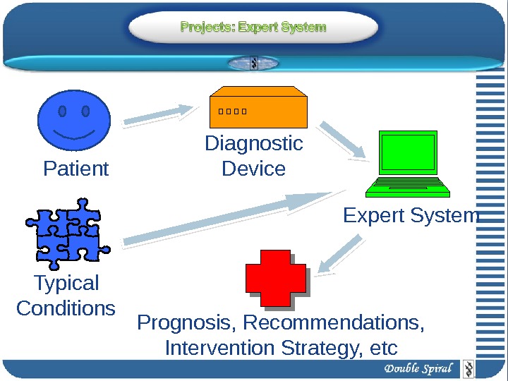
Patient Expert System. Diagnostic Device Prognosis, Recommendations, Intervention Strategy, etc. Typical Conditions
1. Human organism frontiers assesment 2. Variational series : relative PC-based comparison to the CVS performance 3. Transitional processes under load : anaerobiotic – anaerobiotic 4. CVS performance under different loads ( long-time periodic , short intensive, etc. )
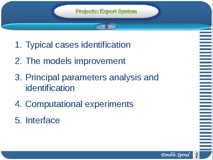
1. Typical cases identification 2. The models improvement 3. Principal parameters analysis and identification 4. Computational experiments 5. Interface
1. Global circulation • Heart – 0 D • Large vessels – 1 D • Capillaries – 2 D 3. Applications Loss of blood Inter-ventricle partition defect Matter transport (inspiration, injection) • Alveolar volumes – 0 D • Bronchial tubes – 1 D 4. Projects 2. Lungs The Heart Thromboembolism Preventive Care Automation Ophtalmic Ishemic Syndrome PC Treatment