
Walking Machine Technology: Medical Field – Disabled


026.cont..walking-robots-design.ppt
- Размер: 10 Mегабайта
- Количество слайдов: 152
Описание презентации Walking Machine Technology: Medical Field – Disabled по слайдам
Walking Machine Technology: Medical Field – Disabled Patients Planetary Exploration Undersea Dredging/Salvage Radioactive Environments (power plants, etc. ) Military Support
Robots from Colorado State University Year Finishes Machine 1986 -87 3 rd Place 1987 -88 1 st Place Lurch 1988 -89 1 st Place Lurch-Next Generation 1989 -90 3 rd Place Lurch II 1990 -91 1 st Place Lurch III 1991 -92 1 st Place Airachnid 1992 -93 1 st Place Airratic 1993 -94 2 nd Place Airratic II 1994 -95 1 st Place X-plorer 1995 -96 1 st Place X-plorer 2 1996 -97 1 st Place K 8 1997 -98 7 th Place Hydrox 1998 -99 4 th Place Team Triad 2000 -01 7 th Place Polyphemus Mobile robots are popular class subjects. Competitions.
Design of a Rough Terrain Vehicle (RTV)
LEGO Parts Kits • 5201 Connectors • 5228/5235 Frame Members • 5267 Shafts, Rigid Couplings • 5269 Bell Cranks, Misc. Links • 5287 Straight Links • 5289 End Connectors, Bushings, Etc Lego is great for gear mechanisms prototyping
LEGO Parts Kits • 9854 Rack & Pinion Gears • 9965 Two sizes, small spur gears • 9966 Two sizes, larger gears • 9966/67 Appear to have same Pitch • 9967 Bevel & Planetary Gears
Gear/Motor Fundamentals • Spur gears have straight teeth • Used to transmit torque and rotation between parallel shafts • Electric motors have high speed and low torque and often must be geared down to slower speed • Motor shaft speed is 350 rpm Spur Gear and Pinion
Gear Fundamentals • Torque times angular velocity is constant between two meshed gears • Angular velocity ratio between two gears is inverse to the size (number of teeth) of each gear • Gears must have same size teeth (pitch) to mesh correctly • Ten to one is the maximum ratio to use between a pair of gears
Simple Gear Trains • A Simple Gear Train has one gear per shaft- each shaft rotates in opposite direction • Speed ratio of train is product of teeth on driver gears/product on driven gears • Simple gear train speed ratio depends on size of first and last gear only
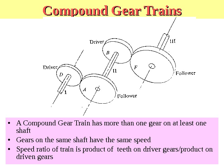
Compound Gear Trains • A Compound Gear Train has more than one gear on at least one shaft • Gears on the same shaft have the same speed • Speed ratio of train is product of teeth on driver gears/product on driven gears
Worm Gear & Worm
Rack & Pinion
Straight Bevel Gears
Measuring Legged Locomotion • Walking is similar to rolling a polygon which has the center located at the swiveling point of the legs and whose side length equals the length of a step. l w p w
Power Required to Walk • Work required to walk is wasted in the consecutive lifting and falling of the center of gravity of the animal body. • The unit power is given in the equation
Great History Moments in Legged Locomotion • 1837 Weber and Weber Measure corpses and show that natural frequency of leg when swinging as compound pendulum is similar to cadence in live walking. • 1872 Muybridge develops stop-motion photography to document running animals. Initially to settle a bet concerning if a horses legs ever all leave the ground during running. • 1893 Rygg patents human-powered mechanical horse. • 1968 Mosher develops quadruped truck at GE. Able to climb railway ties under control of a human driver. • 1977 Gurfinkel develops hybrid computer controlled hexapod walker in USSR. • 1980 Hirose and Umetani demonstrate quadruped machine climbing over obstacles using simple sensors and reflex-like control. The leg mechanism has simplified control.
The Mechanical Horse • Device patented by Lewis Rygg in 1893 • The stirrups double as pedals so the rider can power the stepping motions • The reins move the head and forelegs from side to side for steering • Never built.
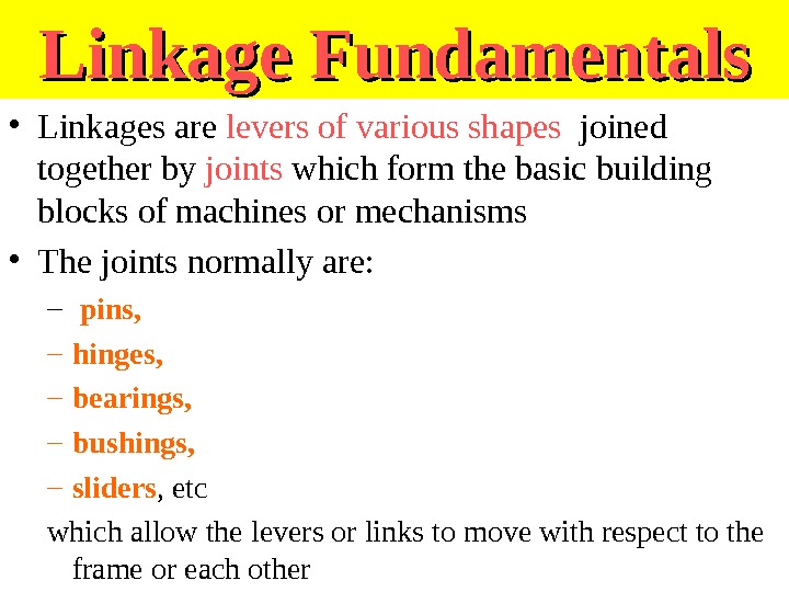
Linkage Fundamentals • Linkages are levers of various shapes joined together by joints which form the basic building blocks of machines or mechanisms • The joints normally are: – pins, – hinges, – bearings, – bushings, – sliders , etc which allow the levers or links to move with respect to the frame or each other
Linkage Fundamentals • Linkages are normally driven by a short lever • This level is also called a crank • Crank is connected to the motor or gear train shaft • A hole in a gear body that is connected to the shaft can define the length of the crank • Linkages are interesting and challenging to work with • They are used in many devices used every day
What is a pivot? • A short rod or shaft about which a related part rotates or swings What is a crank? A device for transmitting rotary motion, consisting of a handle attached at right angles to a shaft. For examples look to the next slide
Generating Walking • When input crank AB rotates, – 1/2 straight path and 1/2 arched path. • Linkages like this consisting of pivots and rigid members are a simple means of generating patterned motion. 1 joint
What are the types of mechanism chains? Linkages are levers of various shapes joined together by joints
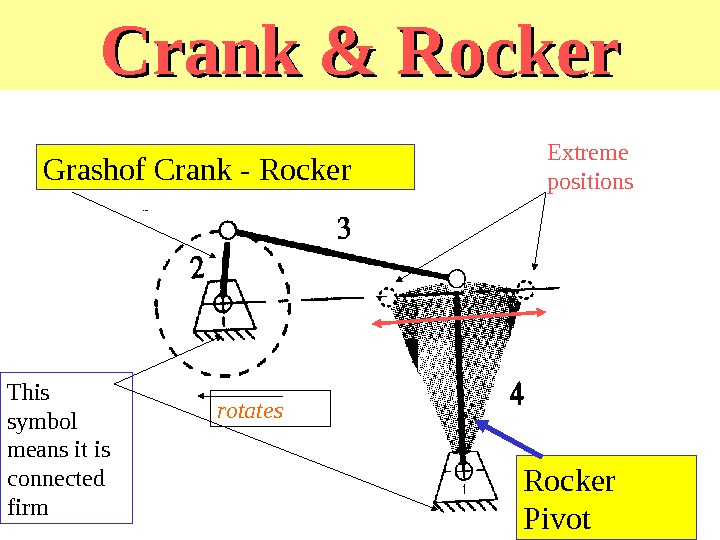
Crank & Rocker Pivot. Grashof Crank — Rocker rotates Extreme positions This symbol means it is connected firm
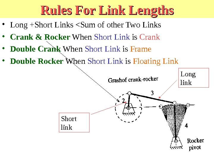
Rules For Link Lengths • Long +Short Links <Sum of other Two Links • Crank & Rocker When Short Link is Crank • Double Crank When Short Link is Frame • Double Rocker When Short Link is Floating Link Short link Long link
Walking-Link Crank & Rocker A four-bar linkage Triangular extension which supports a shoe which can pivot. Used in earth-moving equipment The drive motor can be inside the block The crank and supporting link are connected to a block which is moved forward by the linkage
Equal Link Lengths On Opposite Sides Equal length
Hexapod Six-Legged Robot
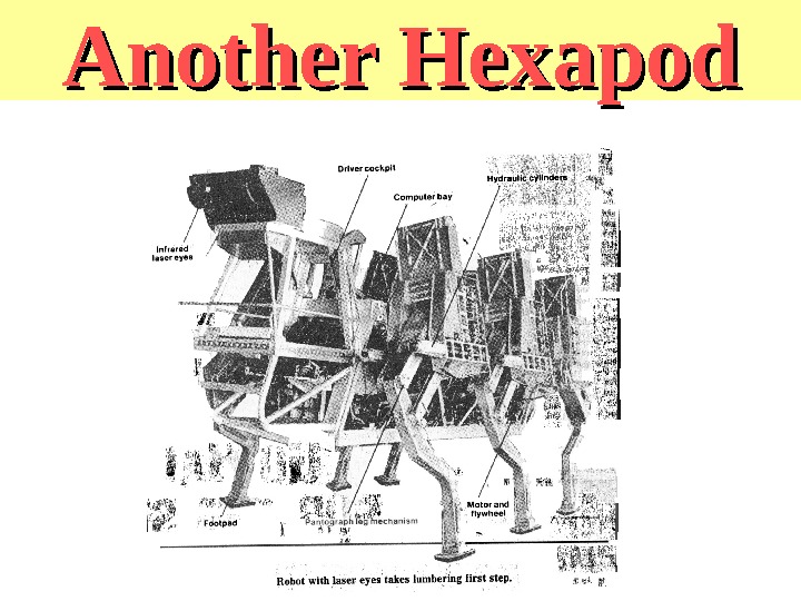
Another Hexapod
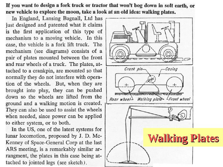
Walking Plates
More Great History Moments • 1983 Odetics demonstrates a self-contained hexapod which lifts and moves back end of pickup truck. • 1983 Raibert demonstrates one-legged machine which hops in place, travels at a specified rate, keeps its balance when disturbed and jumps over small obstacles. • 1987 Waldron and Mc. Ghee demonstrate 3 ton self-contained hexapod carrying human driver which moves at 5 mph over irregular terrain and pulls a load. • 1988 Hodgins and Koechling demonstrate biped which climbs short stairways, jumps over obstacles and sets speed record of 13. 1 mph. • 1997 Honda announces its bipedal walking project which has resulted in an autonomous humanoid.
Two Legged Vehicle—The P 2 • Honda Motor Co. • Obstacle Avoidance by stepping over and around. • can walk stairs, forward or backward, and keep its balance if pushed • Can perform simple tasks autonomously • 15 minute battery capacity
Hexapods from Lynxmotion
Lynxmotion Kits • Hexapods • Cars • Arms • Quadrupeds Lynxmotion Hexapods
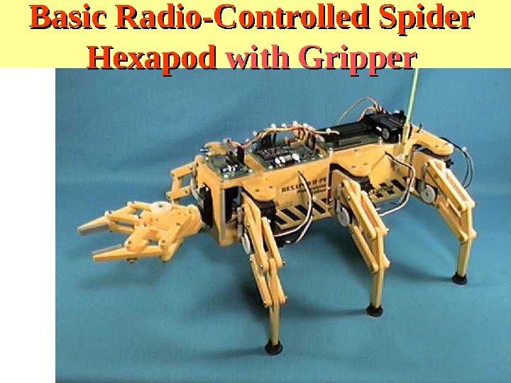
Basic Radio-Controlled Spider Hexapod with Gripper
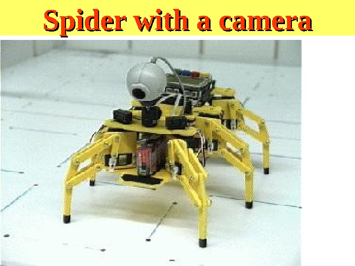
Spider with a camera
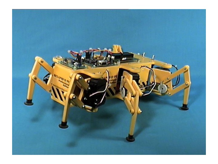
The Hexapod Kit • Hexapod II Kit (body and 12 servos) • A next step micro controller with basic stamp 2 -sx module • 2 Mini. SSCII serial servo controllers • An infrared Proximity detector • Serial LCD Display Module • Wire connector kit • (2) 7. 2 volt Battery Packs & charger • Basic Stamp Programming Pack
Added Wireless Video Camera • Called the XCAM 2 • Purchased from X 10. com • It costs $99. 99 with a battery pack • $79. 99 otherwise
Basic Stamp 2 -SX controller • Microcontroller : Scenix SX 28 AC – Program execution speed : 10, 000 instructions per second – Processor Speed: 50 Mhz • Memory: – Program Memory size: • 8 programs x 2 k Bytes each (16 k Bytes) – Ram Size: • 32 Bytes (6 for I/Os and 26 for variables) – Scratch Pad RAM: • 64 Bytes ( 1 for program ID and 63 for user)
Controller continued… • Inputs/Outputs: 16 + 2 dedicated serial I/O – Current @ 5 v: 60 m. A Run / 200 micro Amps sleep – Source / Sink Current per I/O: 30 m. A / 30 m. A • Connector Socket: 24 pin dip • Programming: – PC Software Text Editor: STAMP@SX. exe – PC Programming interface: Serial Port (9600 Baud) – PBASIC Commands:
Next Step Carrier Board • Basic stamp 2 -sx module plugs into the Next Step Microcontroller • Supplies: – Serial port interface – Pin connectors for easy connection to other items – Buttons and LEDS – Power connections
Component Interconnections • The Next Step has the Basic Stamp 2 module on it • Other components are interfaced to the next step – Serial LCD display – Infrared proximity detector – 2 Mini. SSCII serial servo controllers – Batteries & switches
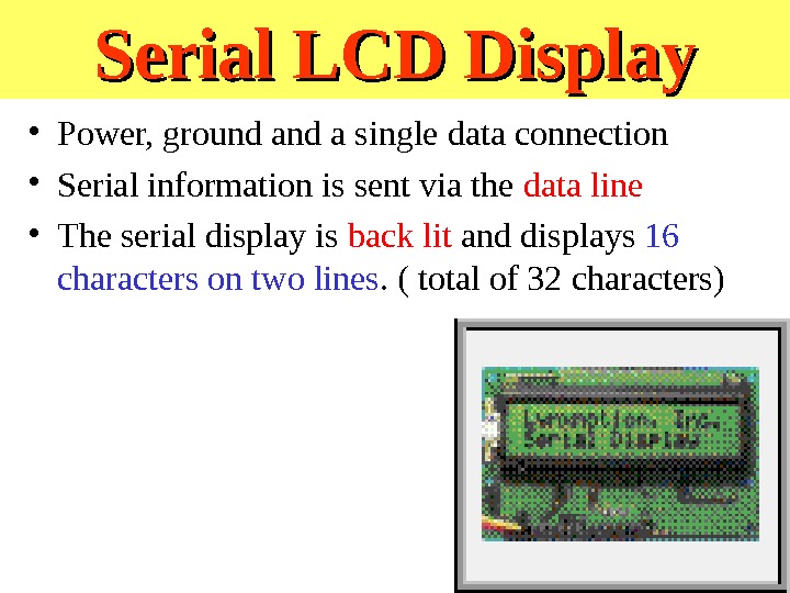
Serial LCD Display • Power, ground a single data connection • Serial information is sent via the data line • The serial display is back lit and displays 16 characters on two lines. ( total of 32 characters)
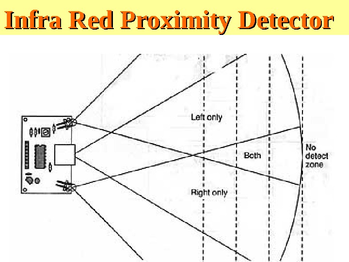
IRPD • IRPD = Infra Red Proximity Detector • Connected to power and ground • Three I/O ports: – Left source – Right source – Detector
Infra Red Proximity Detector
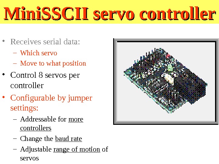
Mini. SSCII servo controller • Receives serial data: – Which servo – Move to what position • Control 8 servos per controller • Configurable by jumper settings: – Addressable for more controllers – Change the baud rate – Adjustable range of motion of servos
Hexapod II Configuration • Two Mini. SSCIIs working together • Six servos per controller: – one controller: 0 to 5 – another controller: 8 to 12 – There are two unused pinouts • Different serial data lines
Servos • Components: – Electric motor – Gearing – Potentiometer – Difference amplifier – Power amplifier
Servo Operation • Potentiometer measures output shaft position • Input signal is sent in • Difference amplifier compares values of input and output values • A driving signal is generated • Signal is amplified • It powers the motor • Output shaft changes potentiometer value • Driving signal changes • Process repeats until the difference signal is zero
Pulse Width Modulation When “high” for 2 m. S, stays in right By controlling the pulse width you change the angle
Notable Features • Variable speed • Input signal is pulse width modulation – Pulses ranging from 1 to 2 milliseconds long repeated 60 times a second
Batteries & Switches • 9 volt battery for the next step • 9 volt battery for the Mini. SSCII • 7. 2 volt Battery pack to power the servos • On off switches for each source
Programming • PBasic programming language • Syntax described in book • Provided text editor • Compiles on PC and downloads via serial port
What have we added? • 2 Radio frequency transceivers – Computer serial port – Onboard robot I/O pin • Video feed to computer • Vision system analysis • Signals to control robot
Hexapod Kit Purchasing • The Lynxmotion Hexapod II Professional Edition Combo kit • Their company web page www. lynxmotion. com • The Mondotronics Robot Store at www. robotstore. com • Current street price : $766.
Problems with Lynxmotion hexapods • Weight – Servos make the vehicle quite top heavy and may add to instability. Is there a way of replacing servo with muscle? • Turns – How? • Sensing – There ain’t any! What happens on uneven ground? • Speed • – Unstable at higher speeds
RHex Other Hexapods
• RHex 0 is the first prototype in the RHex series of hexapod robots. • It has been built in July-August 1999 over a period of roughly 6 weeks at Mc. Gill University. • Inspired by hexapodal insect locomotion, RHex 0 uses an alternating tripod gait. • As such, RHex 0 can run over various types of surfaces ranging from carpet to gravel at speeds up to 0. 6 m/s. • It can traverse obstacles of heights up to 22 cm, or roughly 220% of its ground clearance. • Using the same controllers, it can go over higly irregular «fractal» surfaces with little impact on performance. • Future controllers will also enable RHex 0 to climb stairs and leap. Rhex Hexapod Robot
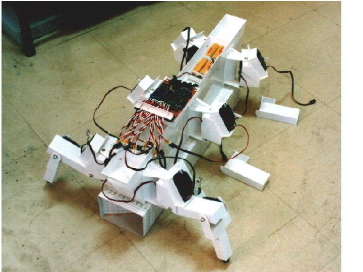
One more hexapod to build Japanese hexapod
Introduction to Japanese hexapod • This is a hexapod robot powered by 18 RC servomotors. • The degree of freedom of each leg is 3. • Built to study the control software for 6 legged locomotion. • This robot can walk in every direction, – but the maximum speed of progress depends on the direction. • Equipped with radio control transmitter and can accept control by radio. • Connected to PC’s parallel port for downloading or/and controlled from PC with umbilical cable.
Introduction to Japanese hexapod
Mechanical Structure and Arrangement The robot consists of 3 major parts: 1. «The Cover», 2. «The Frame», 3. «The Leg-unit». Built to have enough strength and reduce the weight. Introduction to Japanese hexapod
Cover This is the part that looks like tank. It is made from plastic plate. The thickness of the plate is 1(mm) and 0. 3 (mm). The structure is similar to ship’s skeleton. Underside of the cover. This picture shows how the cover keep its shape.
Frame The frame is made from plastic plate. (Thickness is 1 mm) The frame is just an empty box that has three bulkheads at the base of a leg-unit.
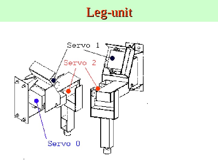
Leg-unit
Layout of servomotors • To increase inertia of parts to be actuated is not good from the point of stability and power consumption of a robot. • All the servomotors are inserted inside of each leg-unit for making it easy to change the arrangement of the legs and to reduce the complexity of the mechanism. • No. 0 and No. 2 servo is connected directly to acquire wide range of the joint movement. • No. 1 servo is connected to No. 1 joint via a linkage to support the weight of the robot. • This picture shows the leg-unit and the frame.
• The leg-units were arranged in line not to interfere each other. • When the robot supports its own weight with three legs (ex. 0, 2, 4), leg 4 must generate two times as much force as leg 0 and 2 generate. • So the maximum total weight of the robot is restricted by the power of leg 1 and 4 for this arrangement. Arrangement of the leg-units
• All the axles that are opposite side of servomotors have a simple mechanism to reduce the cost for the construction and increase productivity. • Don’t expect these axles long life. • The axle consists of 3 mm-diameter bolt and a hole on plastic plate. Mechanism of the joints
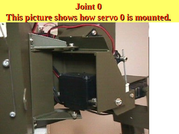
Joint 0 This picture shows how servo 0 is mounted.
• This picture shows around joint 0. The leg-unit is mounted to the frame with 4 2 mm-diameter bolts
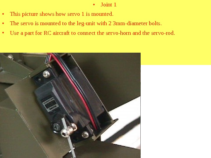
• Joint 1 • This picture shows how servo 1 is mounted. • The servo is mounted to the leg-unit with 2 3 mm-diameter bolts. • Use a part for RC aircraft to connect the servo-horn and the servo-rod.
• This picture shows around joint 1. • Use a part for RC car to connect the leg and the servo-rod
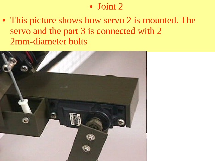
• Joint 2 • This picture shows how servo 2 is mounted. The servo and the part 3 is connected with 2 2 mm-diameter bolts
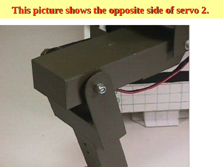
This picture shows the opposite side of servo 2.
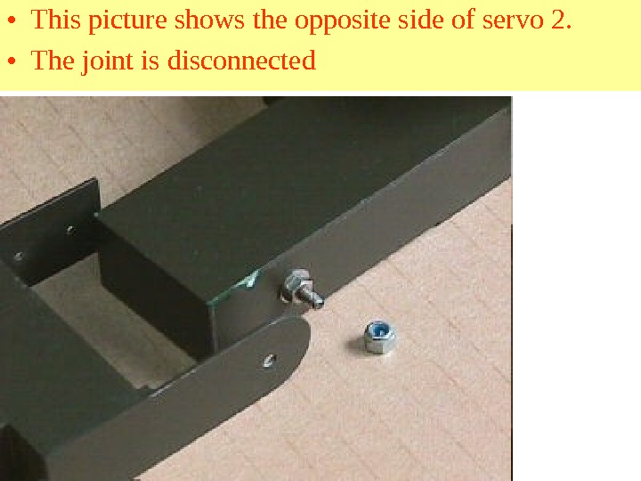
• This picture shows the opposite side of servo 2. • The joint is disconnected
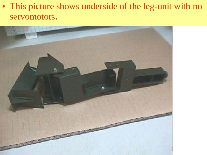
• This picture shows underside of the leg-unit with no servomotors.
Reinforce of the joints • These pictures show leg-unit is reinforced. • The servo-controller for the robot created the signal to move servomotors out of the moving range, when the batteries exhausted. This can break the leg unit.
• Upper part of the joint 0 is reinforced with aluminum plate of 0. 5 mm-thickness.
• The joint 1 is reinforced with plastic plate of 1. 0 mm-thickness. • The base of the servo-rod is reinforced with aluminum plate of 0. 5 mm-thickness
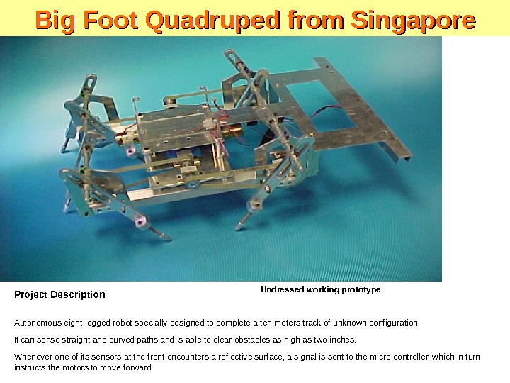
Project Description Autonomous eight-legged robot specially designed to complete a ten meters track of unknown configuration. It can sense straight and curved paths and is able to clear obstacles as high as two inches. Whenever one of its sensors at the front encounters a reflective surface, a signal is sent to the micro-controller, which in turn instructs the motors to move forward. Undressedworkingprototype. Big Foot Quadruped from Singapore
Key Features • Is autonomous • Is compact • Has special retro-reflective sensors for tracking purposes • Has micro-controller and driver circuit to control motor TEMASEK ENGINEERING SCHOOL 21 Tampines. Avenue 1 Singapore 529757 Tel: 7882000 Fax: 7877641 Big Foot Quadruped
Technical Specifications • Rechargeable power source • 12 volt dc supply • Infrared remote wireless control • Range of up to 10 meters • Weight 8. 5 kg Control of the Singapore quaduped: Sequence of operations Students : Chung Chin Chuen Hoo Meng Chan, Jackie Koh Chor Kiat Supervisors: Ms. Siu Yee May, May yeemay@tp. edu. sg Mr. Lee Teck Chin teckchin@tp. edu. sg. NONO YESSTART Both Motors at Maximum Speed Is Sensor 1 Active? Is Sensor 4 Active? Left Motor Speed Reduced 4 Times Left Motor Speed Reduced 2 Times Right Motor Speed Reduced 4 Times. Is Sensor 2 Active? Is Sensor 3 Active? Big Foot Quadruped
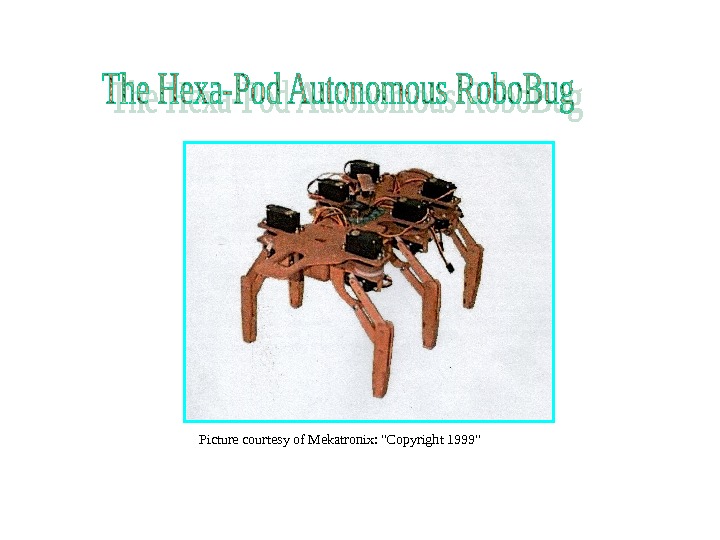
Adaptation of Mekatronix Hexapod
Main Purpose
Design and implement an efficient control system that will allow a six-legged mobile robot demonstrate its mobility, autonomy and versatile characteristics. Reasons why this robot is efficient and reliable • Autonomy • Individual Sub-Control Systems • Economical
The Robot. Main Purpose
Picture courtesy of Mekatronix: «Copyright 1999»
High Level Performance Low Level Performance The Robot. Main Purpose
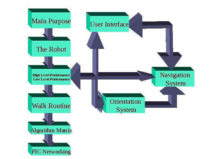
LOW LEVEL PERFOMANCE Controlled by Peripheral Interface Controllers HIGH LEVEL PERFOMANCE Controlled by Motorola 68 HC 12 • Synchronized Motion Routine • User Interface • Orientation System • Navigation System • Sensor Systems • Overall Motion Control
Walk Routine High Level Performance Low Level Performance The Robot. Main Purpose
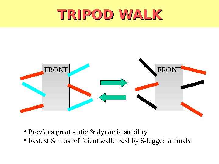
TRIPOD WALK FRONT • Provides great static & dynamic stability • Fastest & most efficient walk used by 6 -legged animals
Algorithm Matrix Walk Routine High Level Performance Low Level Performance The Robot. Main Purpose
Walking Algorithm Matrix Legend ……… Up ……… Down …… Forward …. . Reverse X …. . . Don’t C hange
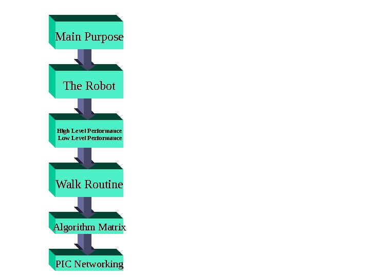
PIC Networking. Algorithm Matrix Walk Routine High Level Performance Low Level Performance The Robot. Main Purpose
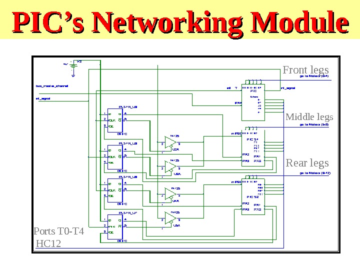
PIC’s Networking Module Front legs Middle legs Rear legs Ports T 0 -T 4 H
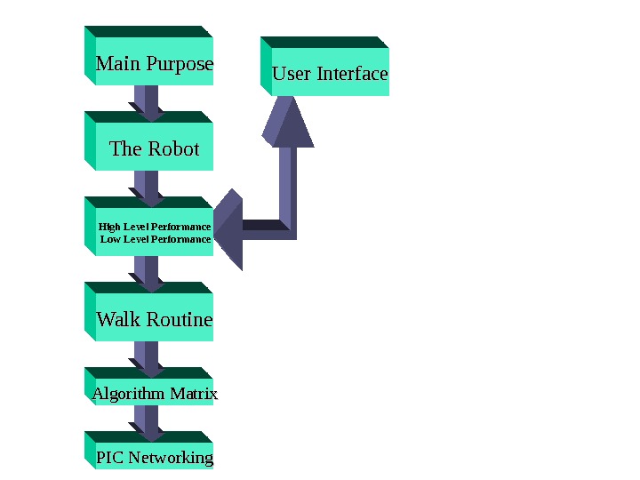
PIC Networking. Algorithm Matrix Walk Routine High Level Performance Low Level Performance The Robot. Main Purpose User Interface
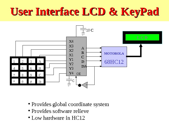
User Interface LCD & Key. Pad L C D 1 2 C 3 6 9 BA 854 7 * 0 # D — X 4 X 3 X 2 X 1 Y 2 Y 3 Y 4 A B C D DA OE C — 10 C MOTOROLA 68 HC 12 • Provides global coordinate system • Provides software relieve • Low hardware in HC 12 Asynchronous Data Entry Onto Bus Configuration
Orientation System PIC Networking. Algorithm Matrix Walk Routine High Level Performance Low Level Performance The Robot. Main Purpose User Interface
Orientation System MOTOROLA 68 HC 12 Port S Port DLC N SW EElectronic Compass L C DReading
Navigation System Orientation System PIC Networking. Algorithm Matrix Walk Routine High Level Performance Low Level Performance The Robot. Main Purpose User Interface
Navigation System XY X = 1, Y = 2 Initialize Coordinates N S E W Read Orientation Read Line Step Cycle Line Detected Fix Positionno yes
Orientation System Navigation System Sensors System. User Interface PIC Networking. Algorithm Matrix Walk Routine High Level Performance Low Level Performance The Robot. Main Purpose
Sensors System 5.
Overall System Diagram SONAR & IR SENSORS MOTOROLA 68 HC 12 1 2 C 3 6 9 BA 854 7 * 0 # DKEYPADLINE TRACKER COMPASS SERVOSPIC ARRAY FUNCTIONAL SUBSYSTEM L
WMC Competiti on on Overview
Polyphemus — — Competition • Complete all events: Dash, Load Retrieval, Slalom, Trip Wire, Object Retrieval, Obstacle Course, Object Seeking and Hill Climb • Compete at Autonomous Level 2 in a maximum number of events. SAE Walking Machine Challenge: Colorado State University, WM
8 -Legged Polyphemus Articulat ed “Legs” On-board Power Self-Cont ained (tethered) Analogy in Nature
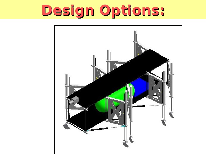
Design Options:
Design Options:
Design Options:
Design Options:
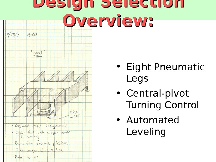
Design Selection Overview: • Eight Pneumatic Legs • Central-pivot Turning Control • Automated Leveling
Polyphemus – Conceptual Design • Mechanical – Vision system constraints – Task defined functionality • Controls – Decision/execution architecture – HL – navigation – LL – motion
Mechanical Design Elements • Vision system constraints – Stability – Consistent height and angle • Task defined functionality – Negotiating obstacles – Repeatable steps
Mechanical Design Solution • Pneumatics – Low cost and environmentally inert – Difficult to control closed-loop • Locomotion – 8 Legs – fully independent – Vertical foot cylinders • Momentary contact switches • Rotary Potentiometers • 2 -axis digital level chips
Controls Design Elements • Parallel development • Architecture – High Level • Image acquisition • Navigation decisions – Low Level • Mechanical status and control • Maneuver execution
Controls Design Solution • HL – Matrox 4 sight – Embedded NT: Object oriented c++ – Imaging: Blob Analysis – Navigation: SW Compass • LL – Stamp IIsx – Feedback inputs: MUX – Code segmentation • Instructions from HL to LL via RS
Polyphemus — Evaluation • Retained design concepts – Variable foot extension – Basic control architecture – Optical position feedback • Design evolution – Reengineered structure – New LLC hardware – Added imaging and navigational functionalities
Vision System PULNi. X black-and-white camera (TM-7 CN) Able to adjust focus and brightness levels Matrox 4 Sight hardware Embedded Windows NT Mouse/keyboard/monitor ports Parallel/Serial ports Ethernet network interface Matrox software Matrox Imaging Library (MIL)
Costs of the Components PULNi. X camera (TM-7 CN) — $793 Matrox 4 Sight hardware — $2, 470 Matrox software — $3,
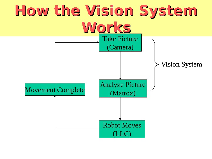
How the Vision System Works Take Picture (Camera) Analyze Picture (Matrox) Robot Moves (LLC)Movement Complete Vision System
Existing Code C++ Microsoft Visual C++ Coding done in classes More than one person can work on code at a time
Class Relation Competition Robot Compass. Serial. Movement Features Imaging. Sight
Matrox Imaging Library (MIL) Foundation of the vision system “ Blob Analysis” Allows the robot to see numbers or objects as “blobs” Blob features: Area Density Location on screen
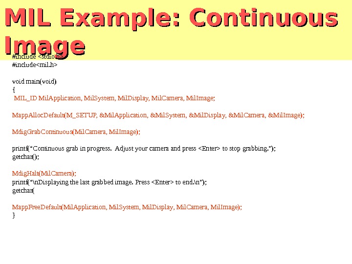
MIL Example: Continuous Image #include #include void main(void) { MIL_ID Mil. Application, Mil. System, Mil. Display, Mil. Camera, Mil. Image; Mapp. Alloc. Default(M_SETUP, &Mil. Application, &Mil. System, &Mil. Display, &Mil. Camera, &Mil. Image); Mdig. Grab. Continuous(Mil. Camera, Mil. Image); printf(“Continuous grab in progress. Adjust your camera and press to stop grabbing. ”); getchar(); Mdig. Halt(Mil. Camera); printf(“\n. Displaying the last grabbed image. Press to end. \n”); getchar( Mapp. Free. Default(Mil. Application, Mil. System, Mil. Display, Mil. Camera, Mil. Image); }
Optical Character Recognition (OCR) Very powerful library Would allow robot to recognize numbers on the course Tries to match an image to a known character/pattern Would be able to start anywhere on the course and know where to go Remains a team goal for next semester
What Are We Controlling? • The low-level controller controls the walking algorithm for the robot • Items being controlled: Pneumatic valves Turning Swivel Motor • Feedback to the Controller: Leg Position Leveling Information Touch Sensing Matrox Vision PLC Control Switches, Valves, Sensors. Low-Level Controls
Low-Level Control Options • Last year’s low-level controller: Parallax Stamp IIsx Limited I/O capabilities Code was not documented at all! • Decision made to find a better low-level controls solution for this year’s robot • Two options were presented: PICs or PL
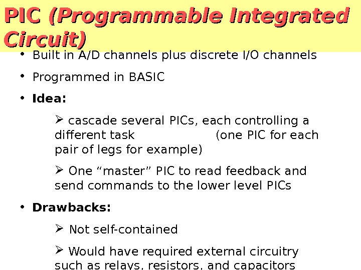
PIC (Programmable Integrated Circuit) • Built in A/D channels plus discrete I/O channels • Programmed in BASIC • Idea: cascade several PICs, each controlling a different task (one PIC for each pair of legs for example) One “master” PIC to read feedback and send commands to the lower level PICs • Drawbacks: Not self-contained Would have required external circuitry such as relays, resistors, and capacitors
PLC (Programmable Logic Controller) • Industrial controller used for applications such as motion control, process control, and automation in general • They are robust systems and can be customized in terms of I/O, power supply, and programming • It is a completely self-contained unit (No external circuitry needed besides power)
Walking Machine I/O Requirements • Outputs: Maximum of 28 discrete DC outputs (valves, swivel foot, and retrieval device included) • Inputs: 8 analog inputs for vertical positioning of legs 4 analog inputs for horizontal positioning of legs 8 discrete DC inputs for touch sensors on each foot Serial in from Tilt Sensor Serial in from Vision System for walking commands
GE Fanuc Series 90 -30 PLCPLCMain Rack Slot 0: 24 VDC power supply Main Rack Slot 1: Series 90 -30 CPU Main Rack Slot 2: Programmable Co-processor (RS-232 compatible) Main Rack Slot 3: 16 Circuit Input Analog Voltage Main Rack Slot 4: 16 Circuit Input 24 VDC Main Rack Slot 5: 16 Circuit Relay Output Main Rack Slot 6: 16 Circuit Relay Output
Series 90 -30 Programming • Programming is done with Ladder Logic Flows like an electrical diagram Simply controlling the opening and closing of contacts at certain times using built in timers • Versa. Pro — Graphically based ladder logic programming software (drag-and-drop implementation) Programming done in Windows environment then downloaded directly to the PLC • Learning ladder logic has begun and will continue into next semester
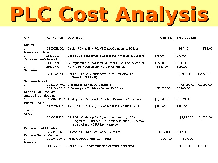
PLC Cost Analysis Qty Part Number Description Unit Net Extended Net Cables 1 IC 690 CBL 701 Cable, PCM to IBM-PC/XT Class Computers, 10 feet $65. 40 Manuals and Info. Link 1 GFK-0255 Series 90 Programmable Coprocessor Module & Support $75. 00 Software User’s Manual 1 GFK-0771 C Programmer’s Toolkit for Series 90 PCM User’s Manual $150. 00 1 GFK-0772 PCM C Function Library Reference Manual $150. 00 Software 1 IC 641 SWP 063 Series 90 PCM Support S/W, Term. Emulator/File $299. 00 Transfer (TERMF) Software Toolkits 1 IC 641 SWP 709 C Toolkit for Series 90 (Standard) $1, 082. 00 1 IC 641 SWP 710 C Developer’s Toolkit for Series 90 PCMs $3, 786. 00 Series 90 -30 Products Analog Input Modules 1 IC 693 ALG 222 Analog Input, Voltage 16 Single/8 Differential Channels $1, 028. 00 Bases / Racks 1 IC 693 CHS 391 Base, CPU, 10 Slots, Use With CPU 331/CSE 331 and $261. 00 above CPUs 1 IC 693 CPU 341 Module (80 K Bytes user memory), 10 K $1, 728. 00 Registers, . 3 msec/K, The battery for the CPU is now included in the CPU backplane box. Discrete Input Modules 1 IC 693 MDL 645 24 Vdc Input, Neg/Pos Logic (16 Points) $217. 00 Discrete Output Modules 2 IC 693 MDL 940 Relay Output, 2 Amp (16 Points) $265. 00 $530. 00 Manuals 1 GFK-0356 Series 90 -30 Programmable Controller Installation $75.
PLC Cost Analysis (continued) Qty Part Number Description Unit Net Extended Net Manuals 1 GFK-0467 Series 90 -30/90 -20 Programmable Controllers Reference $75. 00 Manual Power Supplies 1 IC 693 PWR 322 Power Supply, 24/48 Vdc, Standard. Battery not $350. 00 included. Battery is now included in the CPU backplane box. Special Function Modules 1 IC 693 PCM 300 Prog. Coproc. Mdl. , 160 KB (35 KB Basic Prgm), w/Port $1, 180. 00 Exp. Cbl. Series 90 -70 Products 3. 4 Manuals 1 GFK-0646 C Programmer’s Toolkit for Series 90 -70 User’s Manual $150. 00 Versa. Programming Software Versa. Pro Standard Edition 1 IC 641 VPH 300 Versa. Pro Standard Edition — Windows Programming $683. 00 Software with Programming Cable for Series 90 -30 and Versa. Max PLCs Total Net $11, 884. 40 • Very expensive, but GE Fanuc has agreed to fully sponsor our team • New total cost: $0.
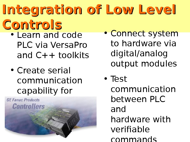
Integration of Low Level Controls • Connect system to hardware via digital/analog output modules • Test communication between PLC and hardware with verifiable commands (tether program) • Learn and code PLC via Versa. Pro and C++ toolkits • Create serial communication capability for system
Reintroduction of Vision System • Integration into low-level controls via serial connection • Verification of initial coding functionality (robot can function at a level at least that of previous year) • Modification of code for event completion and addition of new turning and navigational functionalities
Debugging of Full System • Expected to be most time consuming stage • Debugging of software for vision, step calculation, turn calculation, error handling and event choice • Debugging of hardware including leg movement, leveling, turning, and pneumatics • Testing of integrated system with all controls and viable high-level capabilities included
Goals for Second Semester • Fabrication of physically functional robot • Implementation of PLC as low-level controls • Creation of Optical Character Recognition code • Modification and implementation of existing vision code for new turning and movement capabilities • Implementation of real-time navigation • Taking first place at Walking Machine Challenge
Projected Timeline • Feb. 1, 2002 date of proposed integration of controls, robot, and vision system • Mid-February have machine together and ready for event-debugging • Beginning of March begin working on OCR capabilities • End of March evaluate OCR and robot functionality and determine priorities for competition • Beginning of April have robot ready to compete in each event • April 26 -27, 2002 compete in SAE Walking Machine Competition
Once the previous goals are accomplished the CSU Walking Machine Team will once again dominate the world (of autonomous robot competition).
Problems to Solve for PSU class • 1. Give examples of each of the following joints in real-life mechanisms: – pins, – hinges, – bearings, – bushings, – sliders. • 2. Give examples of robots using each of the above joints. If you do not recall a robot with them, invent a robot with such joints. • 3. Give examples of pivots and cranks.
Problems to Solve • 1. Describe human hand as a kinematic model. How many degrees of freedom. • 2. How to build translation using simple servo motors? • 3. Sketch plans how to use our servo/Robix/Lynxmotion technology to design a model of human arm and hand. How many DOF can you reach? • 4. Give the example with non-controllable DOF. How to control it? • 5. Think how to use the Soccer. Bot design of Karl Kuchs for a more general walking robot design. • 6. Make a plan of a simplest possible useful redundant robot.
Problems to Solve • 7. Describe a holonomic model of human-like simplified hand. • 8. Modify it to make it redundant • 9. Modify it to make it non-holonomic. • 10. Analyze kinematics and inverse kinematics of a model car with one motor, analyze parking in a tight spot from the point of view of inverse kinematics (tough). • 11. Think what are the possible methods to solve inverse kinematics problem. Use knowledge of various classes of algorithms introduced in this class, for instance Genetic Algorithm.
Problems to Solve • 12. How to solve practically in the simplest way the inverse kinematics problem for the OWI arm? You just want to grasp an item in point (x 1, y 1, z 1) and put it back in point (x 2, y 2, z 2). Accuracy not required. • 13. • A). Write a set of cyclic generators for the hexapod from the right. • B). Consider going forward, backward, turning left and turning right as the minimum. • C) Propose a new movement that we do not see on our other hexapods
Sources • Prof. Maja Mataric • Dr. Fred Martin • Bryce Tucker and former PSU students • A. Ferworn , • Prof. Gaurav Sukhatme, USC Robotics Research Laboratory • Paul Hannah • Reuven Granot, Technion • Dr. Raul Torres • Department of Electrical and Computer Engineering, Colorado State University, Senior Design, Fall 2001, • Carlos González, Jardiel Marrero, Carlos Ortiz, Adalberto Santiago • John P. Brach • Jon E. Kappes • Todd K. Kaulukukui • J. Owen Kremzier • Dan C. Malyszko • Peter Young Ph. d. Ryan Fredricey, Jeff Townsend, Joslyn Bollinger, Maile Ceridon, Nicholas Fernandez, William Brennan, Wade Troxell Ph. d.