

МАНЕВРИРОВАНИЕ НА ШЕЛЬФЕ1.pptx
- Количество слайдов: 39
 MANOEUVRING OF THE OFFSHORE SUPPORT VESSELS Training program
 CONTENTS 1. Manoeuvring Systems 2. Tunnel Thrusters 3. Azimuth Thrusters 4. Retractable Azimuth Thrusters 5. Propellers and Rudders 6. Bridge Design, Safe Navigation 7. Manoeuvring in Port and Offshore 8. Dynamic Positioning 9. Monitoring of Diving, ROV, Crane, Survey and other Critical Operations 10. Emergency Situations 11. Typical propulsion systems layouts 12. Manoeuvring of typical AHTS 13. Manoeuvring of AZD AHTS
 Manoeuvring Systems All aspects of Offshore Support Vessels' work scope, whether it involves divers, remotely operated vehicles, survey operations, crane operations or flexible or rigid pipe lay operations, requires the vessel to remain in as stable and as accurate a position as is possible. As such, the manoeuvring systems onboard any Offshore Support Vessel are required to be numerous, powerful and highly efficient. On vessels such as Dive Support Vessels, the requirement to maintain the vessel in a highly accurate position whilst human diver intervention operations take place, requires not only a variety of manoeuvring systems to be in place, but also requires a level of full redundancy in case of system failure or blackout. As such the manoeuvring systems onboard such vessels is far more important in the design and construction of the vessel than in other vessel types. The variety of manoeuvring systems available is quite diverse and the various configurations of thruster types, rudders and propellers that can be utilised is such that it is difficult to describe all the available types. However, the following information is provided to show a general overview of the systems currently in use onboard Offshore Support Vessels and the types of systems that may be encountered within the industry.
 Tunnel Thrusters The runnel thruster is mounted athwartships at the bow or stern inside a cylindrical tunnel. There are two types of tunnel thruster, both of which are most commonly driven by an AC constant speed motor, the L-drive and the Z-drive. The L-drive type tunnel thruster has the controlling motor sited directly above the tunnel thruster unit. The drive shaft unit is fitted vertically into the propeller shaft. The Z-drive type tunnel thruster does not have the controlling motor sited directly above the tunnel thruster unit. Therefore a horizontal shaft is required to connect it to the vertical shaft. Generally the propeller blades will be controllable pitch. Locating shoes on the blades are moved by a sliding yoke mechanism, which alters the pitch as required. The tunnel thruster shown is the most common unit in use and consists of a controllable pitch propeller (CPP) fitted in a cylindrical tunnel leading from one side of the vessel to the other, perpendicular to the vessels fore and aft centreline. The unit shown is fitted with steel rope guards, which are intended to keep debris clear of the propeller blades. In practice however, the guards can often trap debris within the tunnel thus causing more damage than would otherwise occur. The unit can be used to manoeuvre the bow or stern to port or starboard by altering the pitch of the propeller blades. The unit can only be used in these two directions, but pitch and power can be varied. If more than one thruster is fitted, as shown in figure 1. 13, the thrusters can be controlled individually or operated in unison with a single control. Tunnel thrusters are most efficient when the vessel is static. As the vessel speed increases, the flow of water through the athwartships tunnel is retarded. This reduction in the direct water flow results in cavitation and a subsequent reduction in thruster efficiency and is one of the main disadvantages of the thruster type. Advantages of tunnel thrusters include the relative simplicity of the system, which results in reduced maintenance, potential breakdowns and spare part requirements.
 Azimuth Thrusters The azimuth thruster has essentially replaced the standard main propeller and rudder manoeuvring system onboard the majority of Offshore Support Vessels. As such the azimuth thruster is extremely common, both as a stern mounted main propulsion system and also as a forward retractable thruster. The main advantage of such azimuth thusters is the increased manoeuvrability that the fully rotatable system provides in static conditions. However, in comparison to the conventional tunnel thruster and conventional main propeller, the azimuth thruster does not have the same level of reliability. The reasons for this contrasting reliability can be summarised as follows: Increase in draft of the vessel. Although this can be counteracted by the provision of a retractable azimuth thruster, the increase in design requirements and engineering construction of the retractable thruster has its own associated reliability problems. Increased exposure to damage. Increased requirement for an extra bearing and seal arrangement to allow the rotation of the thruster.
 Retractable Azimuth Thrusters The design and operational function of retractable azimuth thrusters is essentially the same as for stern mounted azimuths. However the retractable azimuth thruster, due to its general positioning at the bow of the Offshore Support Vessel, protrudes below the vessel's hull and therefore requires the added complication of a retraction system. This system allows the unit to be retracted into the hull of the vessel to avoid potential damage when operating in shallow water. As with the standard azimuth thrusters, this type of unit provides increased manoeuvrability for the vessel.
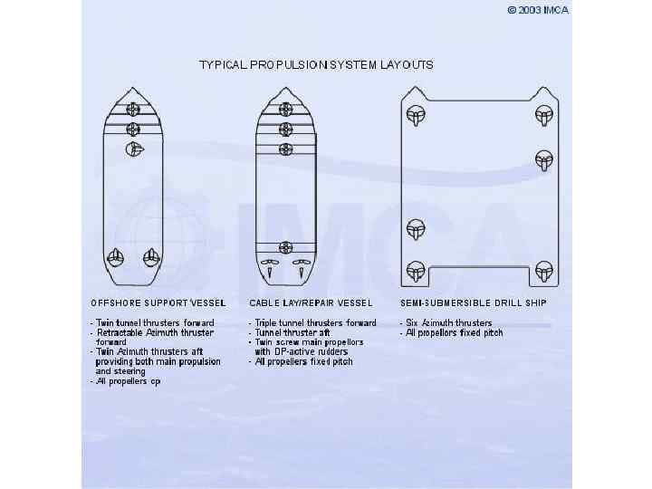
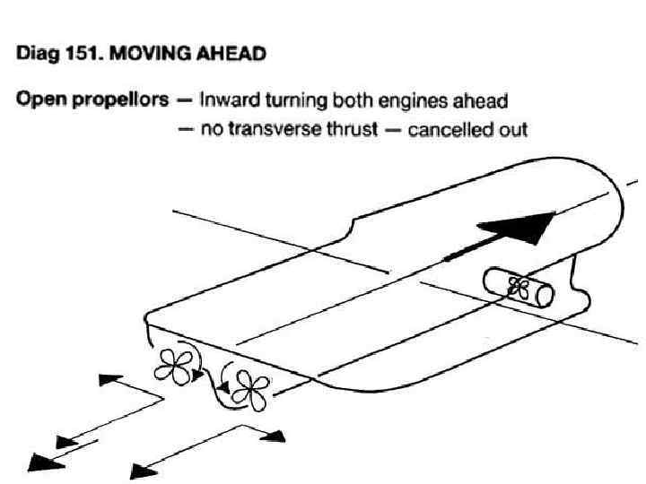
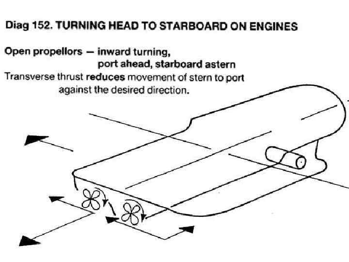
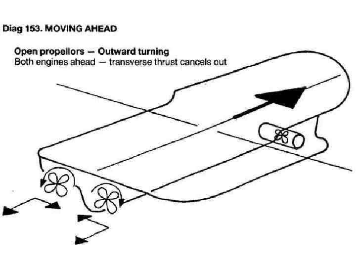
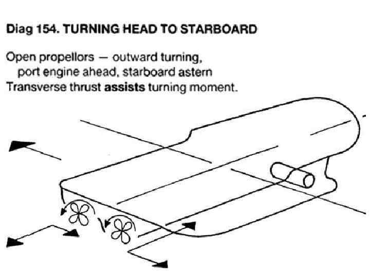
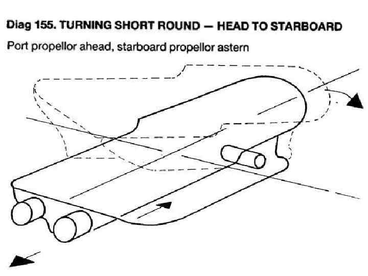
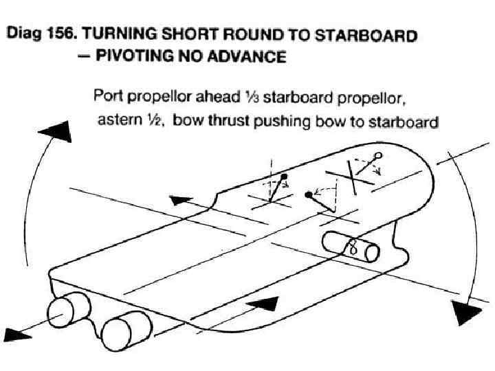
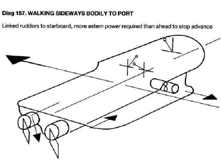
 Propellers and Rudders Although the majority of Offshore Support Vessels are now fitted with azimuth thrusters as their main propulsion systems, many particularly older vessels still have traditional propeller and rudder combinations. A basic understanding of the systems available and their particular functional capabilities is therefore necessary for any deck officer onboard such vessels. As with a standard cargo vessel, the thrust of the single propeller blades can be categorised into two main components. The main component is the fore and aft force that drives the vessel through the water, with an additional and significantly smaller athwartships component, known as transverse thrust. Main propellers can be provided in a variety of different configurations, with single screw, twin screw, right handed and left handed propellers, controllable and fixed pitch blades all common. It is therefore essential to understand how the particular propeller will react when manoeuvring ahead or astern. Single Propeller Vessels A right handed propeller with fixed pitch when providing ahead power will cause a transverse thrust effect with the bow drifting to port. A right handed propeller with fixed pitch when providing astern power will cause a transverse thrust effect with the bow drifting to starboard. A left handed propeller with fixed pitch when providing ahead power will cause a transverse thrust effect with the bow drifting to starboard. A left handed propeller with fixed pitch when providing astern power will cause a transverse thrust effect with the bow drifting to port. A right handed propeller with controllable pitch when providing ahead power, will cause a transverse thrust effect with the bow drifting to port. It should be noted that as the vessel has a controllable pitch propeller, the unit always rotates clockwise (i. e. - to the right) even when the vessel is going astern, therefore the bias or transverse thrust effect is always to lead the bow to port. A left handed propeller with controllable pitch when providing ahead power, will cause a transverse thrust effect with the bow drifting to starboard. It should be noted that as the vessel has a controllable pitch propeller, the unit always rotates anti-clockwise (i. e. - to the left) even when the vessel is going astern, therefore the bias or transverse thrust effect is always to lead the bow to starboard. Twin Propeller Vessels The added complication of twin propellers adds to the potential possibilities with regards to variations in the system types provided. For example, a vessel can be provided with inward turning propellers. One propeller will therefore be left handed and one right handed. Outward turning propellers may also be provided, again with one propeller left handed and one right handed. Twin propellers turning in opposite directions from each other will effectively cancel out the effects of transverse thrust.
 Bridge Design, Safe Navigation Bridge Design Bridge design onboard any Offshore Support Vessel, whether involved in diving, ROV, survey, pipe and product deployment or construction work, is directly related to the type of operations and the working environment to which the vessel will be exposed. Specific design features will be required for specific operations and environments; however the Offshore Support Vessels bridge design should take into consideration the following: Safe Navigation Irrespective of the specific function of any vessel, the safe navigation and transit between port and location and from location to location remains one of the primary concerns of any master and his navigating officers. The bridge design of the vessel should therefore ensure that a forward console is provided with the following navigational and transit systems: A dedicated manual and auto control station for engine, rudder and thruster control. Navigational equipment, including radar, electronic and paper charts, echo sounders and autopilot should be provided, with good all round visibility for navigation and collision avoidance available to the navigating officer. External and internal communications systems should be available at the forward console. In the case of Dive Support Vessels, divers may be expected to be in saturation during transit periods, therefore immediate communication between Dive Control and the bridge is essential. Monitoring of internal safety systems such as fire alarms and watertight door status should be provided. With the introduction of the ISPS Code, the security of the vessel is now a more high level priority and therefore in certain circumstances it may be necessary for camera monitors to be provided on the bridge displaying live feeds from 'critical' areas of the vessel. This may be of particular importance when transiting high risk areas.
 Bridge Design Forward bridge consol conso Aft bridge consol
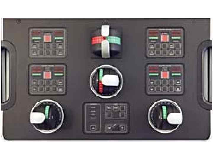
 Manoeuvring in Port and Offshore Generally, Offshore Support Vessels will be set-up and stabilised on DP prior to entering the 500 metre of any installation, therefore manoeuvring at an installation will be conducted in DP mode. However, in port such vessels will generally be manoeuvred in manual control and therefore manual controls must be situated to afford good visibility of the vessel's position. Generally manual and joystick controls will be provided on both bridge wings in addition to the forward and aft consoles. Change over controls from manual to auto and from auto to manual must be situated to ensure easy access and avoid confusion. Such controls must be clearly marked. Whilst manoeuvring, whether from the main forward or aft consoles or from bridge wing stations, direct access to echo sounder displays, heading indicators, weather indicators and any overside camera displays should be available. External and internal communications systems should be available at the forward console and after consoles and at any remote bridge wing stations to allow direct communication between the bridge, engine room and mooring stations.
 Dynamic Positioning It is standard practice for Offshore Support Vessels to position themselves stern to the operations site, dependent of weather and the proximity of obstructions and installations. It is therefore standard practice for Dynamic Positioning operations to be conducted from the after console so that the navigating officers can view the vessel's after deck directly and have a better view of any ongoing operations. However both forward and after DP consoles are the standard on any Offshore Support Vessel. The bridge design of the vessel should therefore ensure that a forward and after console is provided with the following considerations taken into account: Dedicated forward and after control stations should be provided incorporating access to all reference system displays and monitoring systems (such as motion reference units). Whilst in DP mode, whether at the forward or aft consoles, direct access to echo sounder displays, heading indicators, weather indicators and any Overside camera displays should be available. External and internal communications systems should be available at both consoles with immediate and direct access to the engine room, operational control centres (dive, ROV, survey, cranes) and to adjacent installations or other vessels. Monitoring of internal safety systems such as fire alarms and watertight door status should be provided. Although less risk of security breaches may be expected at offshore locations, the security of the vessel remains a high level priority and therefore it may be necessary for camera monitors to be provided on the bridge displaying live feeds from 'critical' areas of the vessel.
 Monitoring of Diving, ROV, Crane, Survey and other Critical Operations Whilst on location, an Offshore Support Vessel may be involved in a variety of operations in close proximity to offshore installations where position keeping capabilities and the awareness of the bridge crew is critical to ensure the safety of the vessel's personnel and / or the integrity of adjacent installations and their own vessel. The bridge design of the vessel should therefore ensure that: A direct and unobstructed view of the after deck is provided, including views of any overside launching systems for diving systems, ROV launch systems and cranes. Whilst operations are being conducted from the vessel, direct access to echo sounder displays, heading indicators, weather indicators and any overside camera displays should be available. External and internal communications systems should be available at both consoles. In the case of diving vessels immediate communication between Dive Control and the bridge is essential. Monitoring of internal safety systems such as fire alarms and watertight door status should be provided. Although less risk of security breaches may be expected at offshore locations, the security of the vessel remains a high level priority and therefore it may be necessary for camera monitors to be provided on the bridge displaying live feeds from 'critical' areas of the vessel.
 Emergency Situations Emergency situations can, due to their very nature, occur at any time and whilst the vessel may be transiting, maneuvering or operating alongside an installation. The provision of emergency equipment and systems is therefore generic for most circumstances to allow the navigating officers and master to command control the vessel during such emergencies. The bridge design of the vessel should therefore include: External and internal communications systems available for direct communications with Dive Control, the engine room, helicopter landing officer, fire parties and emergency teams. Monitoring of internal safety systems such as fire alarms and watertight door status should be provided. Monitoring and control systems for the vessel's ballast and bilge system should be provided for possible damage and collision situations where immediate action may be necessary.
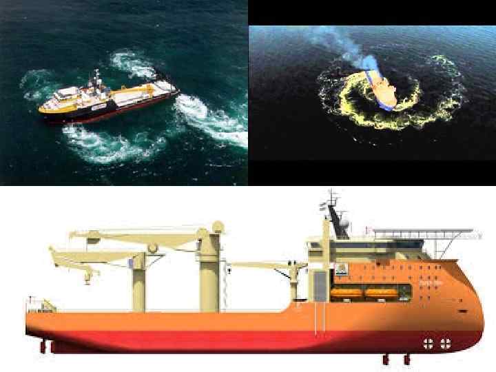
 Typical propulsion systems layouts
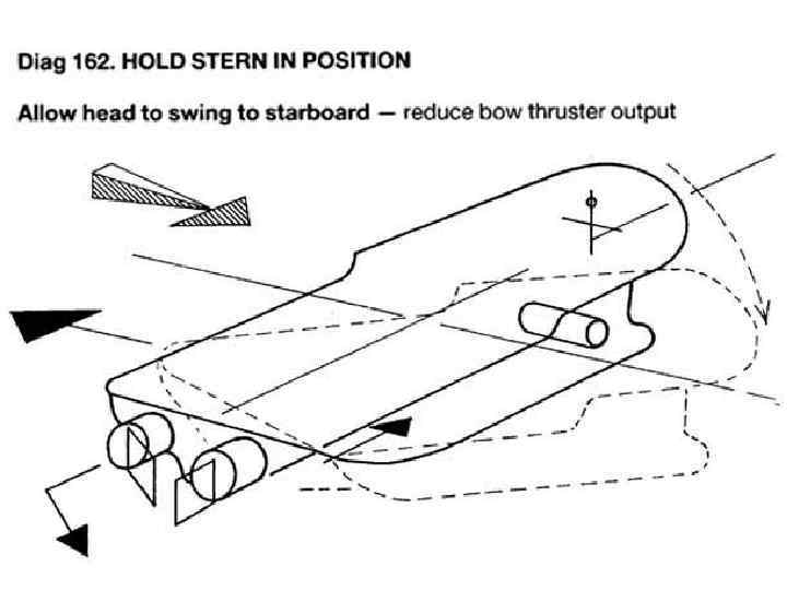
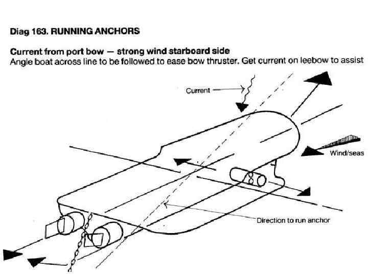
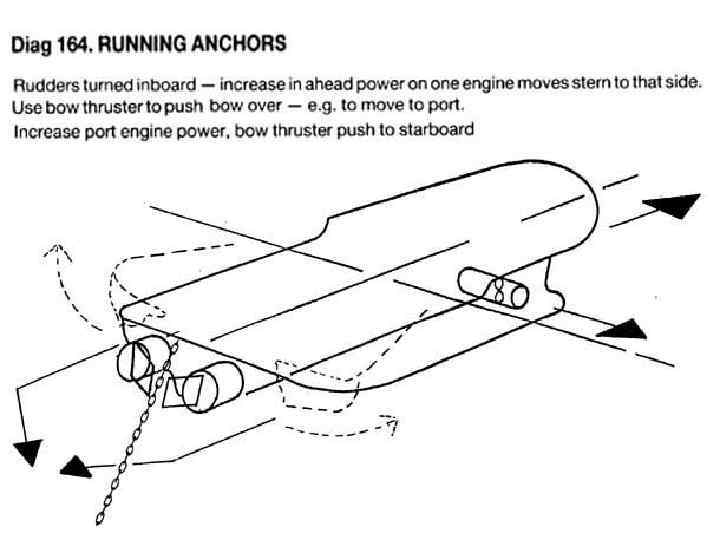
 Manoeuvring of typical AHTS
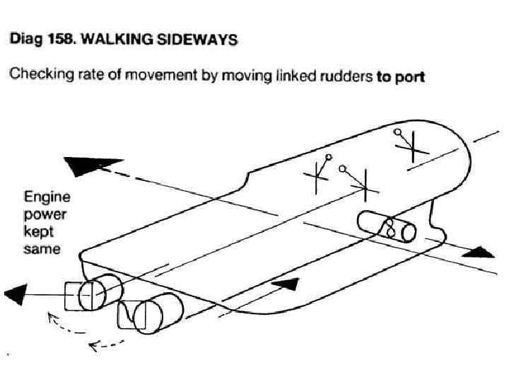
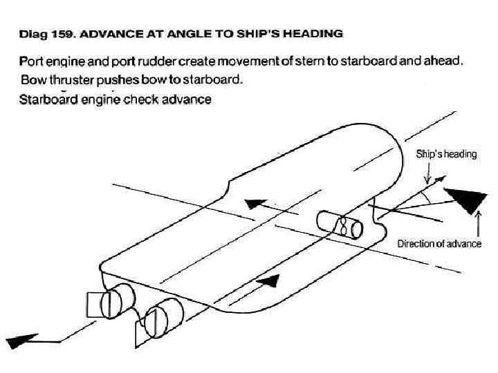
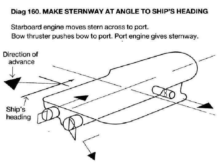
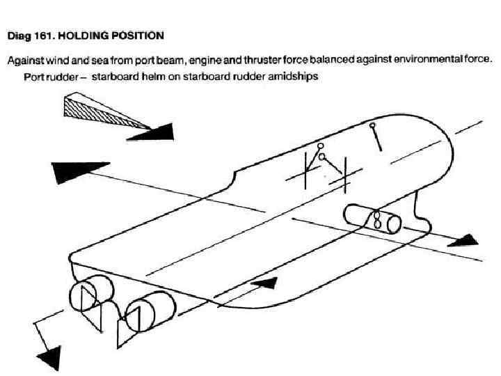
 Manoeuvring of AZD AHTS
 Manoeuvring of AZD AHTS
 Manoeuvring of AZD AHTS
 Manoeuvring of AZD AHTS
 Manoeuvring of AZD AHTS
 Bibliography 1. Демин С. И. Управление судном/Демин С. И. , Жуков Е. И. и др. – М. : Транспорт, 1991. -359 с. 2. Captain Michael Hancox. Oilfield Seamanship Series. Vol. 3, Anchor Handling. OPL, Ledbury, England – 306 c. 3. Captain V. R. Gibson. Supply Ships Operations. OPL, Ledbury, England 1999. – 192 c 4. Gary Ritchie, Master Mariner, BA(Hons) MNI. Offshore Support Vessels. Practical Guide. The Nautical Institute, London, England, 2008. – 164 c 5. Shiphandling simulator course Rotterdam. STC BV. Version 1. 7 Submitted by Captain Oleh Tovstokoryi